NDX-COMPACTMAXRFID handheld reader for animal indentification
Datamars SA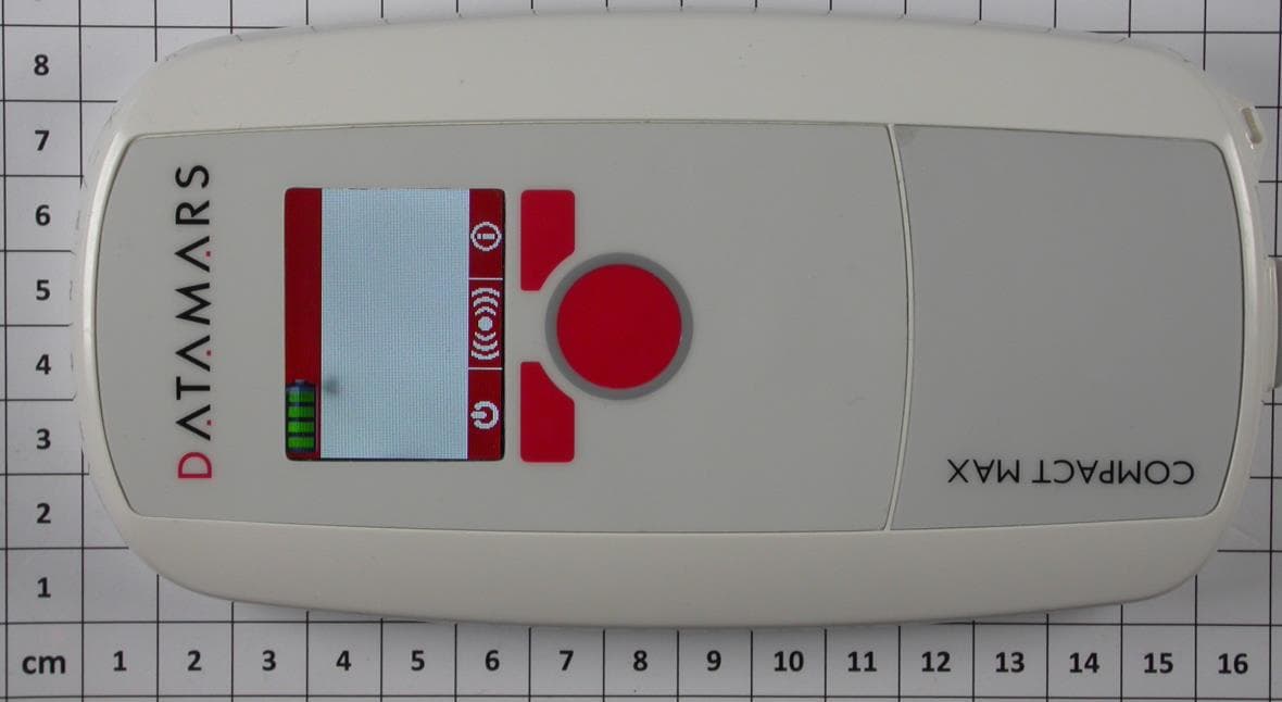
Click to zoom
Application Details
- Equipment Class
- DCD - Part 15 Low Power Transmitter Below 1705 kHz
- Date of Grant
- Aug 17, 2014
- Application Purpose
- Original Equipment
- Date of Application
- Aug 17, 2014
- Equipment Note
- RFID handheld reader for animal indentification
- Frequency Range
- 0.13420000 - 0.13420000
- Company
- Datamars SA
- Country
- Switzerland
Documents & Files
Document Text
Text extracted from the exhibit documents filed with the FCC. Open a document above to read the original.
Users Manual
COMPACT MAX Scanner User Manual COMPACT MAX Reader User Manual 2 05.08.2014 Contents: 1 DESCRIPTION ................................................................................................................................. 3 1.1 SWITCH ON THE SCANNER ....................................................................................................................3 1.2 SWITCH OFF THE SCANNER ...................................................................................................................3 1.3 KEYBOARD ..........................................................................................................................................4 1.3.1 CENTER button ..........................................................................................................................4 1.3.2 LEFT button ................................................................................................................................4 1.3.3 RIGHT button .............................................................................................................................4 2 SCREEN NAVIGATION .................................................................................................................... 5 2.1 DESCRIPTION .......................................................................................................................................5 2.2 CONTROL MENU ..............................................................................................................................6 3 CONNECT THE COMPACT MAX TO A PC .................................................................................... 7 4 TAKE CARE OF THE READER ....................................................................................................... 7 5 SPECIFICATIONS ............................................................................................................................ 7 6 DO YOU HAVE A PROBLEM IDENTIFYING AN ANIMAL? ............................................................ 8 6.1 THE READING DISTANCE IS TOO SHORT ..................................................................................................8 6.2 THE READER DOES NOT READ THE TRANSPONDER .................................................................................8 6.3 THE READER DOES NOT WORK ..............................................................................................................8 7 INFORMATION TO USER ................................................................................................................ 8 7.1 FCC PART 15 ......................................................................................................................................8 7.2 IC RSS 210 ........................................................................................................................................9 8 CERTIFICATIONS ............................................................................................................................ 9 8.1 EUROPEAN DIRECTIVES ........................................................................................................................9 8.2 AMERICAN DIRECTIVES .........................................................................................................................9 9 END OF LIFE .................................................................................................................................. 10 9.1 DISASSEMBLY INSTRUCTIONS FOR COMPACT MAX READER ............................................................. 10 9.2 TOOLS REQUIRED ............................................................................................................................. 10 9.3 PRODUCT DISASSEMBLY PROCESS .................................................................................................... 10 COMPACT MAX Reader User Manual 3 05.08.2014 1 Description 1.1 Switch on the scanner Press the central red button. 1.2 Switch off the scanner Press the left red button to switch off the reader. Antenna Keyboard Display Micro USB communication port COMPACT MAX Reader User Manual 4 05.08.2014 1.3 Keyboard 1.3.1 CENTER button The CENTER button is used to switch on the COMPACT MAX reader, to start and stop a reading session or to select and confirm the various available settings, the settings are described in later chapters of this manual. 1.3.2 LEFT button The LEFT button is used to shut down the reader or to scroll between the various settings. 1.3.3 RIGHT button The RIGHT button is used to access to the CONTROL menu or to return to the previous menu. LEFT button RIGHT button WHEEL CENTER button COMPACT MAX Reader User Manual 5 05.08.2014 2 Screen navigation 2.1 Description Main Menu Active screen after power up. Shut Down Read CONTROL MENU COMPACT MAX Reader User Manual 6 05.08.2014 2.2 CONTROL MENU 15 Digit UID mode 23 Digit UID mode USB Virtual COM Port mode USB Keyboard Wedge mode This figure shows the number of UID stored in the memory. They can be deleted by clicking on the icon. In this folder it can be chosen to start a Cyclic Test, to start a Statistic Test and to Dump the signal. In this folder it can be found which version of COMPACT MAX it is been using and which firmware version is load. In this folder it can be chosen the date, the time and their format. Normal mode Recording mode COMPACT MAX Reader User Manual 7 05.08.2014 3 Connect the COMPACT MAX to a PC The PC can be used for many functionalities: 1. To charge the reader’s battery 2. To configure the reader with the S-ID 3. To use the reader as a Mass Storage device like a USB storage pen 4. To connect the reader with the USB in Virtual Com Port to send or receive data 5. To connect the reader with the USB in Keyboard Wedge mode 4 Take care of the reader Ensure that the reader is not damaged. Do not drop it onto a hard surface or subject it to very wet conditions. If the outer casing of th…
Text truncated - open the document above for the full version.
External Photos
ATTACHMENT A to File No.: T38601-00 CSA Group Bayern GmbH Ohmstrasse 1-4 D-94342 Strasskirchen Tel:+49-9424-9481-0 Fax:+49-9424-9481-440 Photo documentation of the EUT External Views: ATTACHMENT A to File No.: T38601-00 CSA Group Bayern GmbH Ohmstrasse 1-4 D-94342 Strasskirchen Tel:+49-9424-9481-0 Fax:+49-9424-9481-440
Internal Photos
ATTACHMENT A to File No.: T38601-00 CSA Group Bayern GmbH Ohmstrasse 1-4 D-94342 Strasskirchen Tel:+49-9424-9481-0 Fax:+49-9424-9481-440 Internal Views: ATTACHMENT A to File No.: T38601-00 CSA Group Bayern GmbH Ohmstrasse 1-4 D-94342 Strasskirchen Tel:+49-9424-9481-0 Fax:+49-9424-9481-440 ATTACHMENT A to File No.: T38601-00 CSA Group Bayern GmbH Ohmstrasse 1-4 D-94342 Strasskirchen Tel:+49-9424-9481-0 Fax:+49-9424-9481-440 ATTACHMENT A to File No.: T38601-00 CSA Group Bayern GmbH Ohmstrasse 1-4 D-94342 Strasskirchen Tel:+49-9424-9481-0 Fax:+49-9424-9481-440 ATTACHMENT A to File No.: T38601-00 CSA Group Bayern GmbH Ohmstrasse 1-4 D-94342 Strasskirchen Tel:+49-9424-9481-0 Fax:+49-9424-9481-440 Supplied USB cable:
Test Report
FCC ID: NDX-COMPACTMAX CSA Group Bayern GmbH File No. T38601-00-02HU, page 1 of 20 Ohmstrasse 1-4 94342 STRASSKIRCHEN GERMANY Tel.:+49(0)9424-94810 Fax:+49(0)9424-9481440 Rev. No. 3.0, 2014-01-30 EMI − T E S T R E P O R T - FCC Part 15.209 - Test Report No. : T38601-00-02HU 19. August 2014 ______________________________________________________________________________________________ Date of issue Type / Model Name : COMPACT MAX Product Description : RFID handheld reader for animal identification Applicant : Datamars S.A. Address : Via ai Prati CH – 6930 BEDANO Manufacturer : Datamars (Thailand) Co. LTD Address : Northern Region Industrial Estate, 179/1 Moo4 T. Banklang, A. Muang, Lamphoon, 5100 THAILAND Licence holder : Datamars S.A. Address : Via ai Prati CH – 6930 BEDANO Test Result according to the standards listed in clause 1 test standards: POSITIVE The test report merely corresponds to the test sample. It is not permitted to copy extracts of these test results without the written permission of the test laboratory. FCC ID: NDX-COMPACTMAX CSA Group Bayern GmbH File No. T38601-00-02HU, page 2 of 20 Ohmstrasse 1-4 94342 STRASSKIRCHEN GERMANY Tel.:+49(0)9424-94810 Fax:+49(0)9424-9481440 Rev. No. 3.0, 2014-01-30 Contents 1 T E S T S T A N D A R D S 3 2 S U M M A R Y 4 3 E Q U I P M E N T U N D E R T E S T 5 3.1 Photo documentation of the EUT – Detailed photos see Attachment A 5 3.2 Power supply system utilised 5 3.3 Short description of the Equipment under Test (EUT) 5 4 T E S T E N V I R O N M E N T 6 4.1 Address of the test laboratory 6 4.2 Statement regarding the usage of logos in test reports 6 4.3 Environmental conditions 6 4.4 Statement of the measurement uncertainty 6 4.5 Measurement Protocol for FCC, VCCI and AUSTEL 7 5 T E S T C O N D I T I O N S A N D R E S U L T S 8 5.1 Conducted emissions 8 5.2 Field strength of the fundamental wave 14 5.3 Spurious emissions (magnetic field) 9 kHz – 30 MHz 16 5.4 Emission Bandwidth 18 6 U S E D T E S T E Q U I P M E N T A N D A C C E S S O R I E S 20 FCC ID: NDX-COMPACTMAX CSA Group Bayern GmbH File No. T38601-00-02HU, page 3 of 20 Ohmstrasse 1-4 94342 STRASSKIRCHEN GERMANY Tel.:+49(0)9424-94810 Fax:+49(0)9424-9481440 Rev. No. 3.0, 2014-01-30 1 T E S T S T A N D A R D S The tests were performed according to following standards: FCC Rules and Regulations Part 15, Subpart A - General (October, 2013) Part 15, Subpart A, Section 15.31 Measurement standards Part 15, Subpart A, Section 15.33 Frequency range of radiated measurements Part 15, Subpart A, Section 15.35 Measurement detector functions and bandwidths FCC Rules and Regulations Part 15, Subpart C - Intentional Radiators (October, 2013) Part 15, Subpart C, Section 15.203 Antenna requirement Part 15, Subpart C, Section 15.204 External radio frequency power amplifiers and antenna modifications Part 15, Subpart C, Section 15.205 Restricted bands of operation Part 15, Subpart C, Section 15.209 Radiated emission limits, general requirements ANSI C63.4: 2003 Methods of Measurement of Radio-Noise Emissions from Low- Voltage Electrical and Electronic Equipment in the Range of 9 kHz to 40 GHz. ANSI C95.1:1992 IEEE Standard for Safety Levels with respect to Human Exposure to Radio Frequency Electromagnetic Fields, 3 kHz to 300 GHz CISPR 16-4-2: 2003 Uncertainty in EMC measurement Mobile and portable devices RF exposure procedures and equipment authorisation policies 447498 D01 General RF exposure Guidance v05r01, 5/28/2013 FCC ID: NDX-COMPACTMAX CSA Group Bayern GmbH File No. T38601-00-02HU, page 4 of 20 Ohmstrasse 1-4 94342 STRASSKIRCHEN GERMANY Tel.:+49(0)9424-94810 Fax:+49(0)9424-9481440 Rev. No. 3.0, 2014-01-30 2 S U M M A R Y GENERAL REMARKS: The EuT is working at frequency of 134.2 kHz. It is possible to have a Data connection via USB to a PC. FINAL ASSESSMENT: The equipment under test fulfills the EMI requirements cited in clause 1 test standards. Date of receipt of test sample : acc. to storage records Testing commenced on : 04. August 2014 Testing concluded on : 07. August 2014 Checked by: Tested by: Klaus Gegenfurtner Teamleader Radio Huber Markus FCC ID: NDX-COMPACTMAX CSA Group Bayern GmbH File No. T38601-00-02HU, page 5 of 20 Ohmstrasse 1-4 94342 STRASSKIRCHEN GERMANY Tel.:+49(0)9424-94810 Fax:+49(0)9424-9481440 Rev. No. 3.0, 2014-01-30 3 E Q U I P M E N T U N D E R T E S T 3.1 Photo documentation of the EUT – Detailed photos see Attachment A 3.2 Power supply system utilised Power supply voltage: : Tx 4.00 V / DC Rx 3.00 V / DC 3.3 Short description of the Equipment under Test (EUT) The EuT is a RFID handheld reader for animal identification. Number of tested samples: 1 Serial number: ALPHA-00005 EUT operation mode: The equipment under test was operated during the measurement under the following conditions: - Tx mode at 134.2 kHz - Accu charging mode - EUT configuration: The following peripheral devices and interface cables were connected during the measurements: - USB cable male type A to micro USB, 1.0 m Model : Supplied by manufacturer Power Supply CASIO, Model: AD-C53U Supplied by CSA - Model : - Model : - Model : - Model : - Model : - customer specific cables - unscreened power cables FCC ID: NDX-COMPACTMAX CSA Group Bayern GmbH File No. T38601-00-02HU, page 6 of 20 Ohmstrasse 1-4 94342 STRASSKIRCHEN GERMANY Tel.:+49(0)9424-94810 Fax:+49(0)9424-9481440 Rev. No. 3.0, 2014-01-30 4 T E S T E N V I R O N M E N T 4.1 Address of the test laboratory CSA Group Bayern GmbH Ohmstrasse 1-4 94342 STRASSKIRCHEN GERMANY 4.2 Statement regarding the usage of logos in test reports The accreditation and notification body logos displayed in this test report are only valid for standards listed in the accreditation or notification scope of CSA Group Bayern GmbH. 4.3 Environmental conditions During the measurement the environmental conditions were within the listed ranges: Temperature: 15-35 ° C Humidity: 30-60 % Atmospheric pressure: 86-106 kPa 4.4 Statement of the mea…
Text truncated - open the document above for the full version.
Test Setup Photos
FCC ID: NDX-COMPACTMAX CSA Group Bayern GmbH File No. T38601-00-02HU, page 8 of 20 Ohmstrasse 1-4 94342 STRASSKIRCHEN GERMANY Tel.:+49(0)9424-94810 Fax:+49(0)9424-9481440 Rev. No. 3.0, 2014-01-30 5 TEST CONDITIONS AND RESULTS 5.1 Conducted emissions For test instruments and accessories used see section 6 Part A 4. 5.1.1 Description of the test location Test location: Shielded Room S2 5.1.2 Photo documentation of the test set-up FCC ID: NDX-COMPACTMAX CSA Group Bayern GmbH File No. T38601-00-02HU, page 14 of 20 Ohmstrasse 1-4 94342 STRASSKIRCHEN GERMANY Tel.:+49(0)9424-94810 Fax:+49(0)9424-9481440 Rev. No. 3.0, 2014-01-30 5.2 Field strength of the fundamental wave For test instruments and accessories used see section 6 Part CPR 1. 5.2.1 Description of the test location Test location: OATS1 Test distance: 3 metres 5.2.2 Photo documentation of the test set-up 5.2.1 Applicable standard According to FCC Part 15C, Section 15.209: The emissions from intentional radiators shall not exceed the effective field strength limits. 5.2.2 Description of Measurement The spurious emissions of the EUT have to be measured at an open area test site in the frequency range from 9 kHz to 1000 MHz using a tuned EMI receiver. The set up of the equipment under test will be in accordance with ANSI C63.4. The measurement has been performed at 3 m. The results have been compared to the limits defined at 30 m or 300 m distances according to FCC Part 15C, Section 15.31(f)(2) using an inverse linear distance extrapolation factor of 40 dB/decade. The final measurement has been performed with the EMI receiver using Quasi peak detector except for the frequency bands 9 kHz to 90 kHz and 110 to 490 kHz where an average detector will be used, according to Section 15.209(d). The resolution bandwidth during the measurement is as follows: 9 kHz – 150 kHz: RBW: 200 Hz 150 kHz – 30 MHz: RBW: 9 kHz FCC ID: NDX-COMPACTMAX CSA Group Bayern GmbH File No. T38601-00-02HU, page 16 of 20 Ohmstrasse 1-4 94342 STRASSKIRCHEN GERMANY Tel.:+49(0)9424-94810 Fax:+49(0)9424-9481440 Rev. No. 3.0, 2014-01-30 5.3 Spurious emissions (magnetic field) 9 kHz – 30 MHz For test instruments and accessories used see section 6 Part SER 1. 5.3.1 Description of the test location Test location: OATS1 Test distance: 3 metres 5.3.2 Photo documentation of the test set-up 5.3.3 Applicable standard According to FCC Part 15C, Section 15.209: The emissions from intentional radiators shall not exceed the effective field strength limits. 5.3.4 Description of Measurement The spurious emissions of the EUT have to be measured at an open area test site in the frequency range from 9 kHz to 1000 MHz using a tuned EMI receiver. The set up of the equipment under test will be in accordance with ANSI C63.4. The measurement has been performed at 3 m. The results have been compared to the limits defined at 30 m or 300 m distances according to FCC Part 15C, Section 15.31(f)(2) using an inverse linear distance extrapolation factor of 40 dB/decade. The final measurement has been performed with the EMI receiver using Quasi peak detector except for the frequency bands 9 kHz to 90 kHz and 110 to 490 kHz where an average detector will be used, according to Section 15.209(d). The resolution bandwidth during the measurement is as follows: 9 kHz – 150 kHz: RBW: 200 Hz 150 kHz – 30 MHz: RBW: 9 kHz FCC ID: NDX-COMPACTMAX CSA Group Bayern GmbH File No. T38601-00-02HU, page 18 of 20 Ohmstrasse 1-4 94342 STRASSKIRCHEN GERMANY Tel.:+49(0)9424-94810 Fax:+49(0)9424-9481440 Rev. No. 3.0, 2014-01-30 5.4 Emission Bandwidth For test instruments and accessories used see section 6 Part MB. 5.4.1 Description of the test location Test location: AREA4 5.4.2 Photo documentation of the test set-up Fundamental [kHz] See Plot 1 20dB Bandwidth F1 20dB Bandwidth F2 Measured Bandwidth [kHz] 134.20 133.965 134.445 0.48 Remarks:
Contact Information
Applicant
Damien Pachoud(CTO)
Technical Contact
Test Firm
CSA Group Bayern GmbHFrank Scharnowski
Technical Specifications
| # | Rule Parts | Frequency Range | Power Output |
|---|---|---|---|
| 1 | 15C | 0.1342 MHz - 0.1342 MHz | - |
Other Applications from Datamars SA
NDX-OMNIMAX2
Jun 02, 2026RFID Scanner with Bluetooth Low Energy
Equipment Class
DCD - Part 15 Low Power Transmitter Below 1705 kHzNDX-PLCAT1
May 04, 2026NINA-B4
Equipment Class
DTS - Digital Transmission SystemNDX-GW2
Sep 19, 2024Activetag Edge Gateway
Equipment Class
DXX - Part 15 Low Power Communication Device Transmitter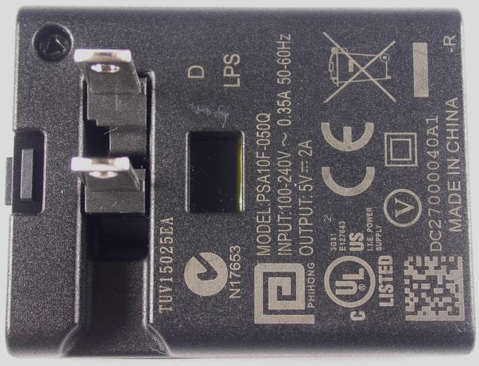
NDX-OMNIMAX
Jan 19, 2014RFID handheld reader for livestock applications
Equipment Class
JBP - Part 15 Class B Computing Device Peripheral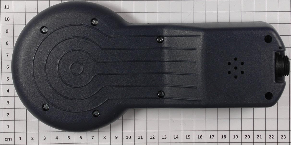
NDX-TRACKING1
Dec 16, 2013RFID handheld reader for livestock applications
Equipment Class
JBP - Part 15 Class B Computing Device Peripheral