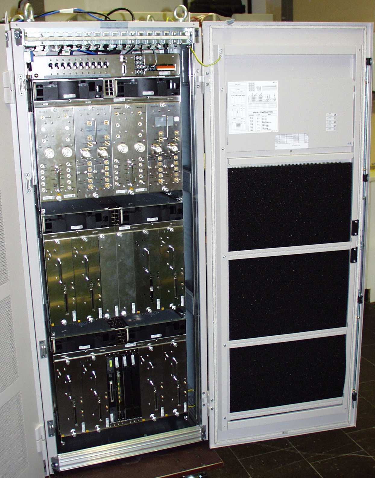
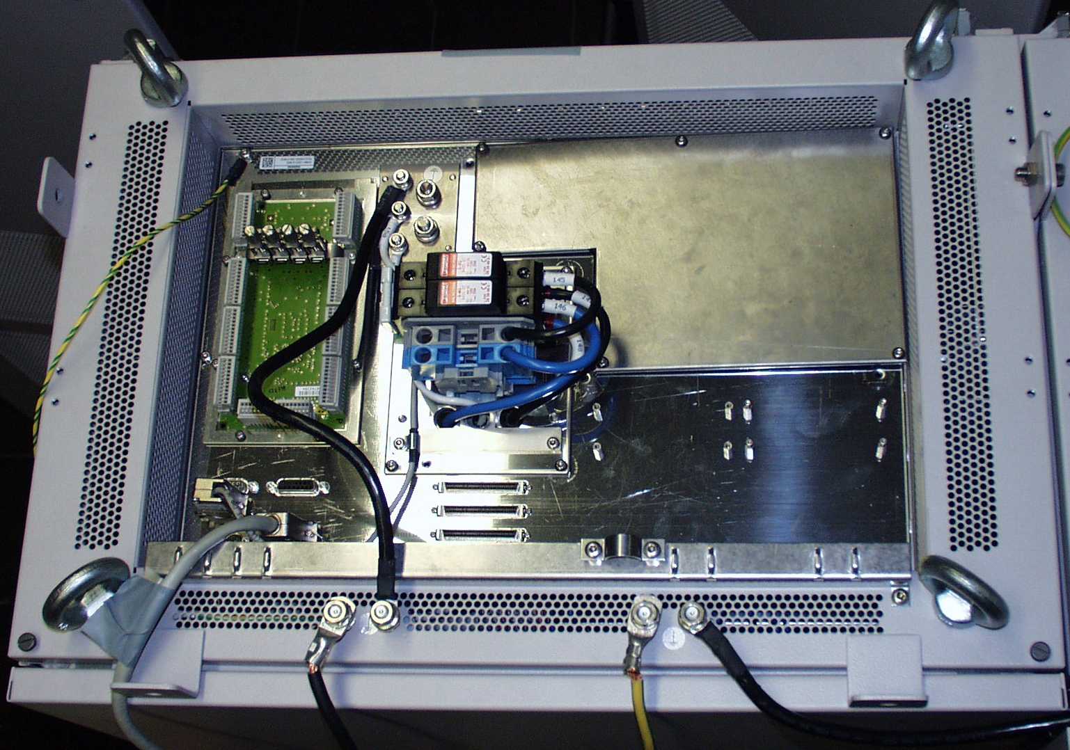
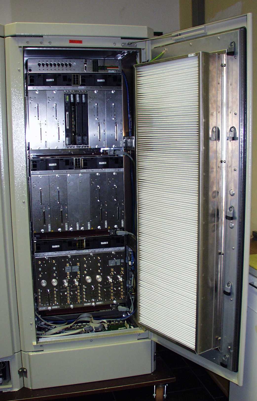
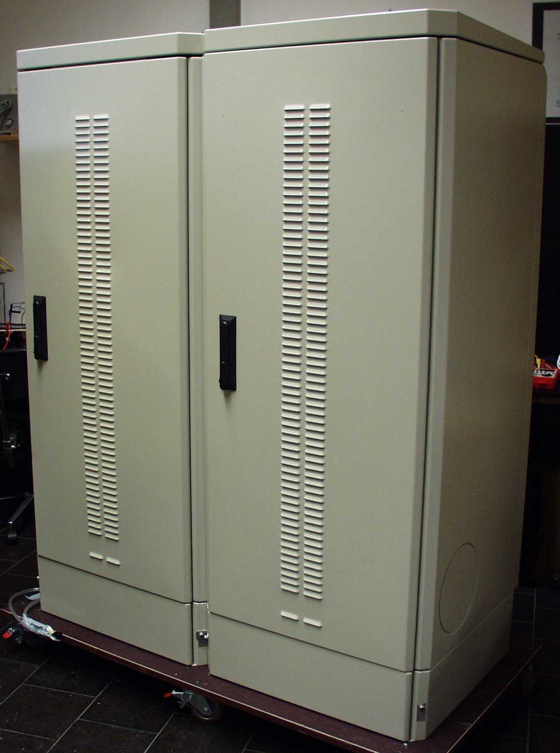
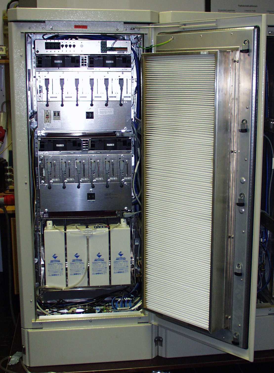
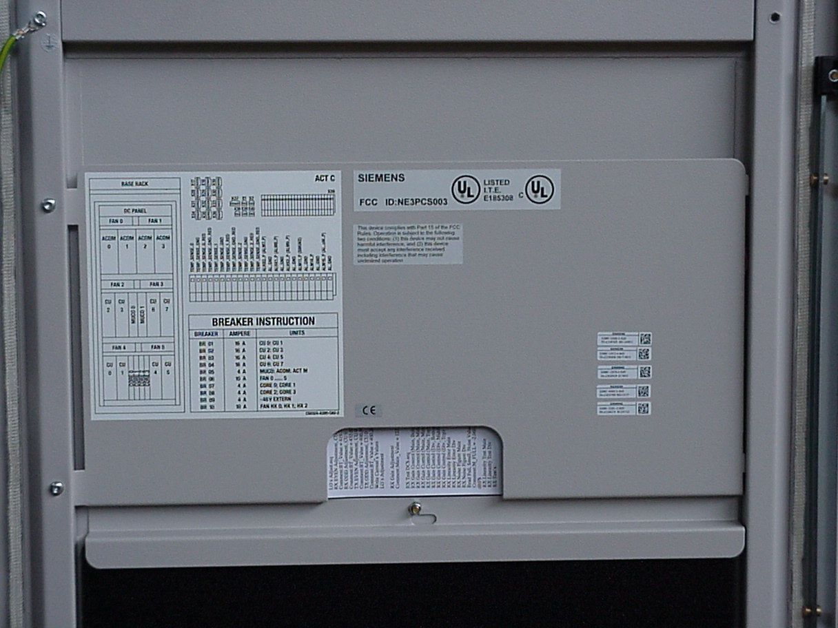
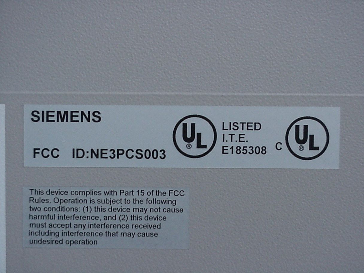
NE3PCS003BS240/BS241 Base Station
Nokia Solutions and Networks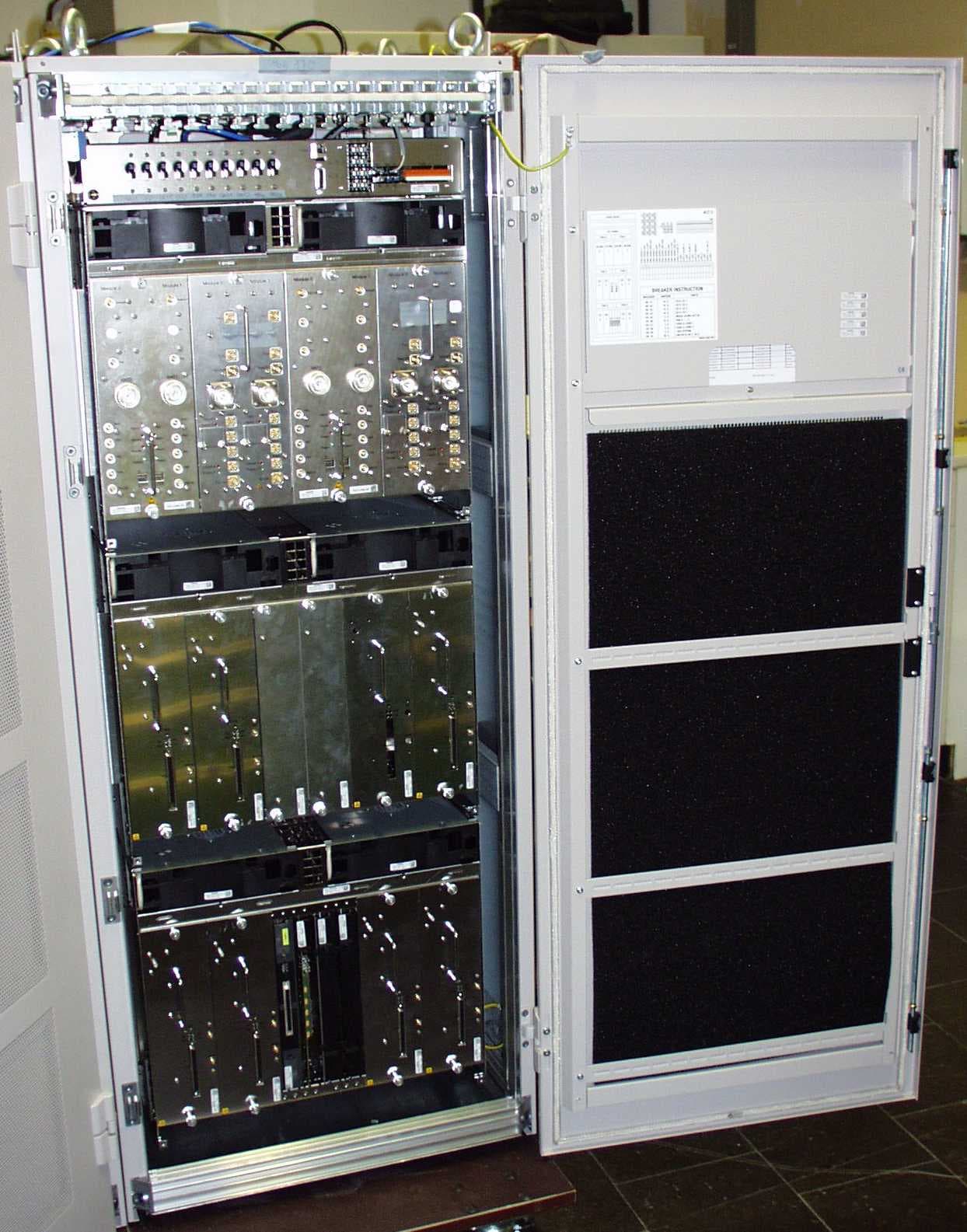
Click to zoom
Application Details
- Equipment Class
- PCB - PCS Licensed Transmitter
- Date of Grant
- May 15, 2000
- Application Purpose
- Original Equipment
- Date of Application
- Apr 10, 2000
- Equipment Note
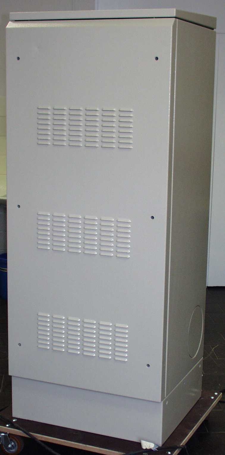
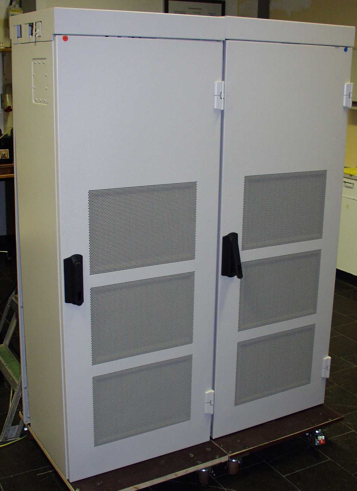
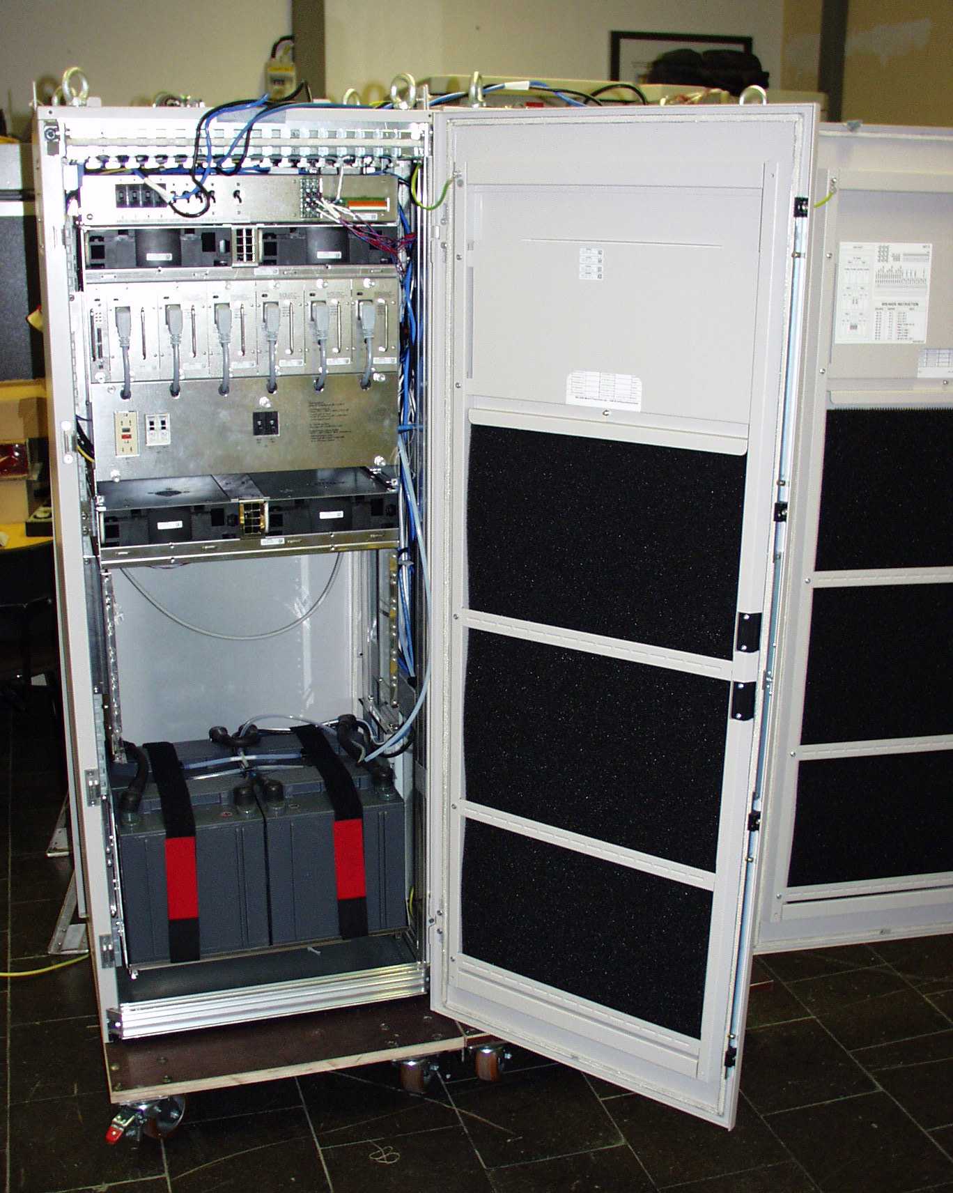
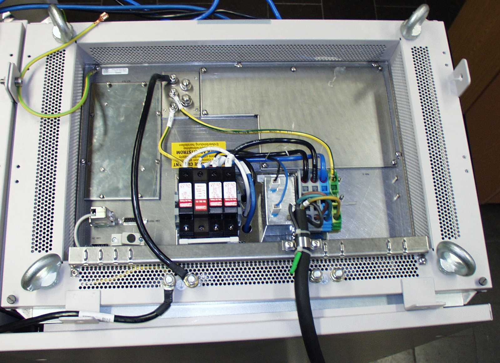
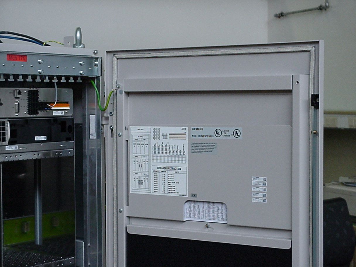
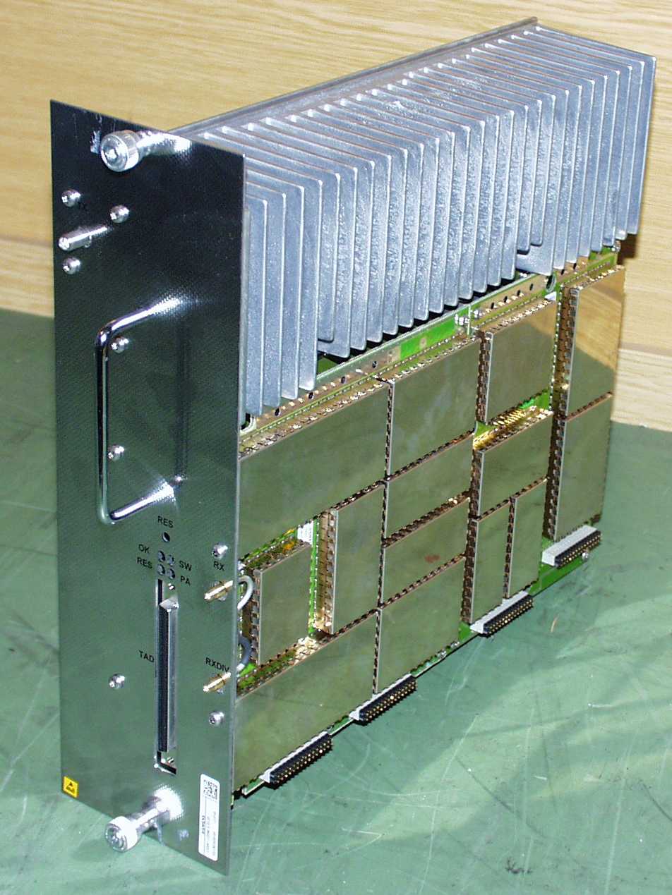
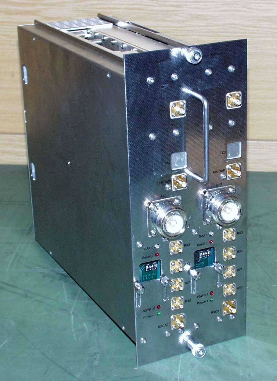
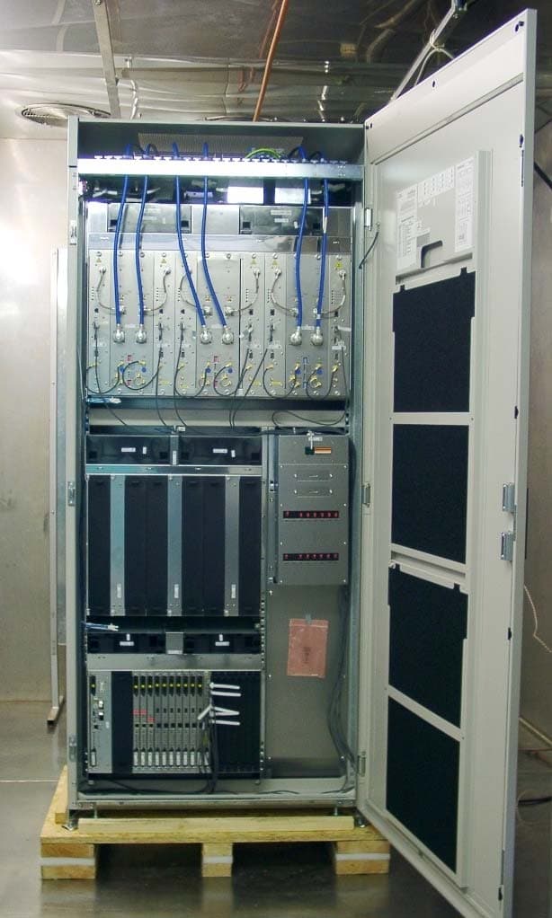
- BS240/BS241 Base Station
- Frequency Range
- 1930.40000000 - 1989.60000000
- Company
- Nokia Solutions and Networks
- Country
- United States
Documents & Files
Document Text
Text extracted from the exhibit documents filed with the FCC. Open a document above to read the original.
Attestation Statements
FCC ID:NE3PCS003 April 12, 2000 Federal Communications Commission Authorization and Evaluation Division 7435 Oakland Mills Road Columbia, MD 21046 Subject: Attestation Statement Reference:FCC ID: NE3PCS003 To Whom It May Concern, Anti-Drug Statement: Siemens Information and Communication Networks, Inc. certifies that, in the case of an individual applicant, he or she is not subject to denial of federal benefits, pursuant to Section 5301 of the Anti-Drug Abuse Act of 1988, 21 U.S. 853 (a), or, in the case of a non-individual applicant (e.g. corporation, partnership, or other unincorporated association), no party to the applicant is subject to denial of federal benefits, that includes FCC benefits, pursuant to that section. For the definition of “party” for these purposes, see 47 CFR 1.2002 (b). Sincerely, Prodip Chaudhury Director, Product Line Management and Systems Engineering e-mail : [email protected] Communication On Air Division Siemens Information and Communication Networks, Inc. (561) 955-6451
Cover Letter(s)
FCC ID:NE3PCS003 April 12, 2000 Federal Communications Commission Authorization and Evaluation Division 7435 Oakland Mills Road Columbia, MD 21046 Subject: PCS Certification Application Cover Letter Reference:FCC ID: NE3PCS003 To Whom It May Concern, This is an application for Certification for FCC ID: NE3PCS003, for models 240 and 241 PCS base stations. These two models are electronically identical, except for the housing. The model 240 is designed to operate in an indoor environment and the model 241 is designed to operate in an outdoor environment. NOTE : We are requesting confidentiality for the following Exhibit Types : Operational description, parts list/tune-up info., schematics, block diagrams, and user manuals. However, while uploading various attachments, we inadvertently did not mark the confidentiality check mark for one file for the exhibit type “Block Diagrams”. Please change the application to include this file for confidentiality. Please do not hesitate to contact me, if you have any questions. Sincerely, Rashmi Contractor Manager, Systems Engineering e-mail : [email protected] Communication On Air Division Siemens Information and Communication Networks, Inc. (561) 955-6454
Cover Letter(s)
Certification Application FCC ID:NE3PCS003 Name of Applicant Siemens Information and Communication Networks, Inc. 900 Broken Sound Parkway Boca Raton, FL 33487 FCC ID:NE3PCS003 96182Page 2/ 17 13.04.2000 Certification Application Contents I. INTRODUCTION.................................................................................................... 4 II. BASE STATION FUNCTIONAL OVERVIEW.......................................................... 4 A.Block diagram .....................................................................................................................................................4 B.EUT......................................................................................................................................................................5 .Overview..........................................................................................................................................................5 .CU ....................................................................................................................................................................5 .DUAMCO.........................................................................................................................................................6 C.Digital control boards .........................................................................................................................................6 D.Special references...............................................................................................................................................6 III.TYPE OF EMISSION........................................................................................... 6 IV.FREQUENCY RANGE......................................................................................... 6 A.Frequency range .................................................................................................................................................6 B.Disabled carrier frequencies at the band edges of each licensed frequency block ........................................7 V. RANGE OF OPERATING POWER VALUES AND DESCRIPTION OF ANY MEANS PROVIDED FOR VARIATION OF OPERATING POWER ............................................. 8 VI.MAXIMUM POWER RATING .............................................................................. 8 VII. DC VOLTAGE AND DC CURRENT..................................................................... 9 VIII. FUNCTION OF EACH SEMICONDUCTOR.......................................................... 9 IX.CIRCUIT DIAGRAMS......................................................................................... 9 X. USERS MANUAL.................................................................................................. 9 XI.DESCRIPTION OF THE TUNE UP PROCEDURE ERROR! BOOKMARK NOT DEFINED. A.Board level tests .................................................................................................... Error! Bookmark not defined. FCC ID:NE3PCS003 96182Page 3/ 17 13.04.2000 .RFTX tests........................................................................................................ Error! Bookmark not de fine d. .PA tests............................................................................................................. Error! Bookmark not de fine d. B.Final factory test.................................................................................................... Error! Bookmark not defined. C.Start-up and supervision........................................................................................ Error! Bookmark not defined. XII. DESCRIPTION OF THE FREQUENCY STABILIZATION ................................... 12 A.Overview ...........................................................................................................................................................12 B.Long Te rm Stability..........................................................................................................................................12 C.Short te rm stability...........................................................................................................................................12 XIII. DESCRIPTION OF CIRCUITS FOR SUPPRESSION OF SPURIOUS RADIATION, LIMITING MODULATION AND POWER.................................................................... 14 A.Suppre ssion of spurious radiation....................................................................................................................14 B.Suppre ssion of spurious radiation and limiting of modulation at the ante nna inte rface...............................14 .Overview: ......................................................................................................................................................14 .Block diagram: TX-path.................................................................................................................................14 .Limiting of modulation....................................................................................................................................14 C.Suppre ssion of spurious radiation....................................................................................................................14 D.Limiting of output power..................................................................................................................................14 XIV.DESCRIPTION OF MODULATION SYSTEM .................................................. 15 A.Theoretical description.....................................................................................................................................15 B.Implementation .................................................................................................................................................15 XV. REFERENCE DOCUMENTS ...............................................................…
Text truncated - open the document above for the full version.
Test Report
Test Plan and Test Results FCC ID:NE3PCS003 Name of Applicant Siemens Information and Communication Networks, Inc. 900 Broken Sound Parkway Boca Raton, FL 33487 BS240/241 BTS PCS Base Station FCC ID:NE3PCS003 95515Page 2/6111.04.2000 TABLE OF CONTENTS 1EQUIPMENT UNDER TEST (EUT)4 2MEASUREMENTS5 2.1G e ne ral de scription5 2.2Summary of the measurements5 2.2.1EUT configuration and operating conditions5 2.2.2Selected carrier test frequencies6 2.2.3Modulation characteristics6 2.2.4Measurement test configuration6 2.2.5Calibration of the measurement equipment7 2.3Test No. 1: RF power output (§ 2.1046)8 2.3.1Purpose8 2.3.2EUT operation condition8 2.3.3Test configuration8 2.3.4Measurement procedure8 2.3.5Measurement results8 2.4Test No. 2: Modulation characteristics (§ 2.1047, § 2.201)9 2.5Test No. 3: Occupied bandwidth (§ 2.1049)10 2.5.1Purpose10 2.5.2EUT operation condition10 2.5.3Test configuration10 2.5.4Measurement procedure and results10 2.6Test No. 4: Spurious emissions at antenna terminals (§ 2.1051, § 2.1057, § 24.238)11 2.6.1Purpose11 2.6.2Limits11 2.6.3EUT operation condition11 2.6.4Test configuration11 2.6.5Measurement procedure and results11 2.7Test No. 5: Field strength of spurious radiation (§ 2.1053, § 2.1057, § 24.238)14 2.7.1Purpose14 2.7.2Limits and field strength calculations14 2.7.3EUT operation condition14 2.7.4Test configuration15 2.7.5Measurement procedure15 2.7.6Measurement results & limits15 2.8Te st No. 6: Fre que ncy stability (§ 2.1055, § 24.235)16 2.8.1Purpose16 2.8.2Limits16 2.8.3EUT operation condition16 2.8.4Test configuration16 FCC ID:NE3PCS003 95515Page 3/6111.04.2000 2.8.5Measurement procedure17 2.8.6Measurement results17 2.9Test No. 7: Slow frequency hopping18 2.9.1Introduction18 2.9.2Purpose18 2.9.3EUT operation condition18 2.9.4Test configuration18 2.9.5Measurement procedure18 2.9.6Measurement results18 3MEASUREMENT DATA AND SPECTRAL PLOTS20 3.1Part list of the measurement test equipment20 3.2Spectral plots21 FCC ID:NE3PCS003 95515Page 4/6111.04.2000 1 Equipment under test (EUT) The equipment under test (EUT) comprises the modules listed in the table below. For a functional description of the modules, please refer to the appropriate related parts and exhibit sections of this certification application. The tests were conducted with the modules installed in a BS-240U and in a BS-241U. Worst case measurement data is reported. The tested system was equipped as per Fig. 1 on page 6 with its maximum number of 8 transceivers. Although only one transceiver (EUT) was tested for compliance, the other transceiver was investigated to ensure that the worst case test condition/transceiver was measured. To comply with the FCC rules (§2.1051, §24.238), the lowest and highest authorized channel frequencies in each of the PCS frequency blocks are disabled and cannot be activated by the user. Refer to section IV of the “Certification Application Overview”, located in the cover letter section, for details on how the channe ls are disable d. A complete description of the transceiver’s calibration/tuning procedure is included in the Parts List and TuneUp exhibit section of this application. Module NameSiemens Part No.Serial No. DUAMCO2PV4S30861-U2105-X-01/01FMM/M1000000 CUPV4S30861-U2094-X-B1/01RX+/M2409183 CUPV4S30861-U2094-X-B1/01RX+/M2409184 FCC ID:NE3PCS003 95515Page 5/6111.04.2000 2 Measurements 2.1 General description 2.2 Summary of the measurements The measurements described in the following sections were conducted pursuant to 47 CFR § 2.947. All applicable paragraphs of the 47 CFR parts 2 and 24 of the most current version of the rules were considered. The measurements were performed at Siemens AG, Institute for Quality Engineering, Testing, and Approvals, Hofmannstr. 51, 81359 Munich, Germany. The following tests were performed according to the FCC rules in order to verify the compliance of the EUT with the FCC requirements: In accordance with the FCC Rule §15.3 (z) the equipment was tested with the limits that are valid for an unintentional radiator . 2.2.1 EUT configuration and operating conditions If not stated otherwise, the following standard setup procedure for the EUT under test was used: A CMD57 is used to control the EUT. The CMD57 is connected to the EUT via the A bis Link. For detailed test system equipment configuration please refer to Fig. 1 on page 6. The transmitter modules were tuned up according to the procedure described in the TuneUp exhibit section of this application. During the measurements, one carrier channel was tested at a time. The carrier was set to the maximum power level with all timeslots activated to ensure the maximum emission amplitudes during all measurements. A pseudo random bit pattern was applied to the digital modulator in order to produce the maximum modulation. This ensures that the measurements of the emission characteristics of the transmitter are pursuant to § 2.1049. Te st No.Me asure me ntFCC RulePage Numbe r of this Report Re sults 1RF power output§ 2.10468compliant 2Modulation characteristics§ 2.1047, § 2.2019compliant 3Occupied bandwidth§ 2.104910compliant 4Spurious emissions at antenna terminals § 2.1051, § 2.1057,§ 24.238 11compliant 5Field strength of spurious radiation § 2.1053, § 2.1057,§ 24.238 14compliant 6Frequency stability§ 2.1055, § 24.23516compliant 7Slow frequency hoppingN/A18compliant FCC ID:NE3PCS003 95515Page 6/6111.04.2000 2.2.2 Selected carrier test frequencies The measurements were performed at 3 selected carrier test frequencies, according to the following table: 1 2.2.3 Modulation characteristics The modulation characteristic of the GMSK modulation used in the PCS system is defined in standard J-STD-007 Air Interface Specification Volume 1. During all measurements described below, a pseudo random sequence was applied to the digital modulator to ensure emission characteristics of the transmitter are pursuant to § 2.1049. 2.2.4 Measurement test configuration If not stated otherwise, the following measu…
Text truncated - open the document above for the full version.
Contact Information
Applicant
Steve Mitchell
Technical Contact
Siemens Information And Communication Networks, InRashmi J Contractor
[email protected]561-955-6454
900 Broken Sound Parkway · Boca Raton, Florida · United States
Non-Technical Contact
Siemens Information Communication Networks, Inc.Rashmi J Contractor
[email protected]561-955-6454
Test Firm
SGS Germany GmbHJosef Bauer
Technical Specifications
| # | Rule Parts | Frequency Range | Power Output | Emission | Tolerance |
|---|---|---|---|---|---|
| 1 | 24E | 1.93 GHz - 1.99 GHz | 23.99 W | 245KGXW | 0.0000050000 % |
Other Applications from Nokia Solutions and Networks
NE3PCS101
Feb 13, 2006850 MHz CAT40, DUAMCO
Equipment Class
TNB - Licensed Non-Broadcast Station Transmitter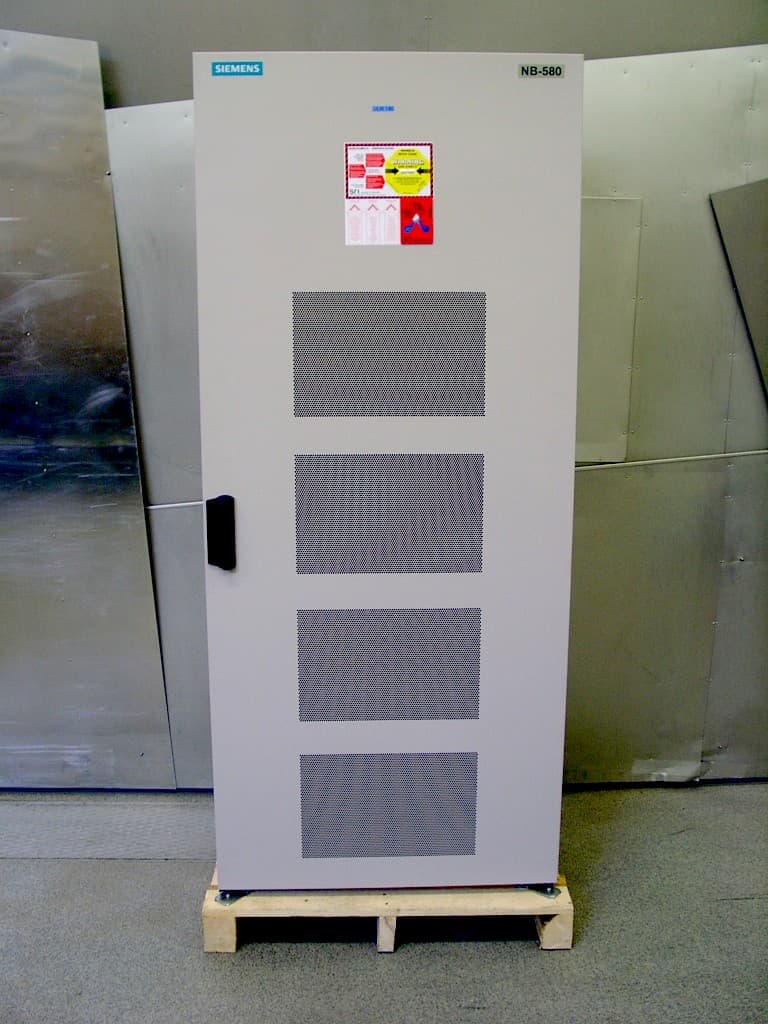
NE3PCS100
Jun 09, 20051900 MHz CAT40, DUAMCO
Equipment Class
PCB - PCS Licensed Transmitter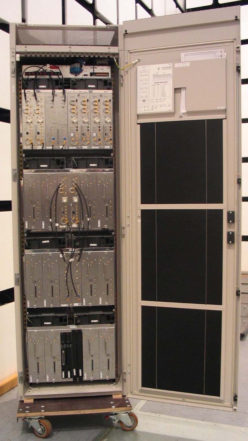
NE3PCS011
Mar 08, 20051900MHz FLEXCU AND FDUAMCO
Equipment Class
PCB - PCS Licensed Transmitter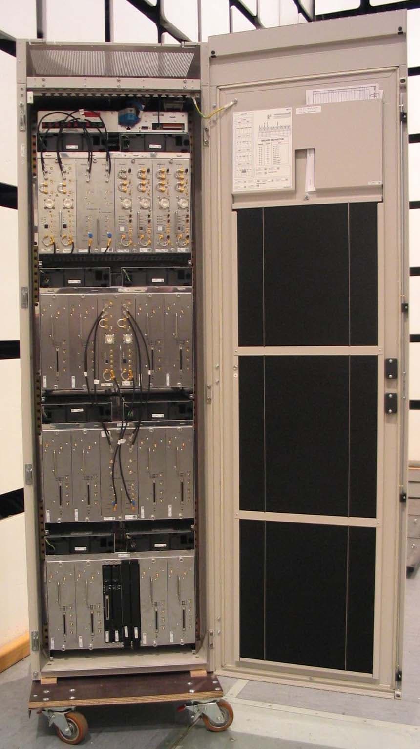
NE3PCS010
Mar 08, 2005850MHz FLEXCU AND FDUAMCO
Equipment Class
TNB - Licensed Non-Broadcast Station Transmitter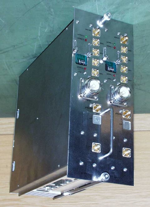
NE3PCS009
Dec 08, 2002High Power 1900 MHz Edge CU
Equipment Class
PCB - PCS Licensed Transmitter