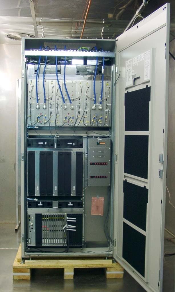
NE3PCS007BS240/BS241 Base Station
Nokia Solutions and Networks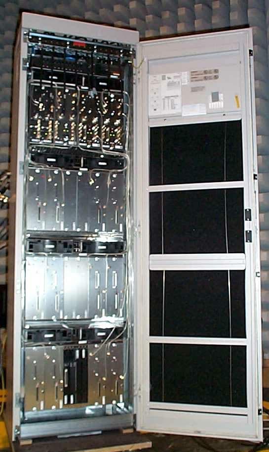
Click to zoom
Application Details
- Equipment Class
- TNB - Licensed Non-Broadcast Station Transmitter
- Date of Grant
- Jun 20, 2002
- Application Purpose
- Original Equipment
- Date of Application
- Mar 12, 2002
- Equipment Note
- BS240/BS241 Base Station
- Frequency Range
- 869.40000000 - 893.60000000
- Company
- Nokia Solutions and Networks
- Country
- United States
Documents & Files
Document Text
Text extracted from the exhibit documents filed with the FCC. Open a document above to read the original.
Attestation Statements
s FCC ID: NE3PCS007 March 15, 2002 Federal Communications Commission Authorization and Evaluation Division 7435 Oakland Mills Road Columbia, MD 21046 Subject:Attestation Statement Reference:FCC ID: NE3PCS007 To Whom It May Concern: Anti-Drug Statement: Siemens Information and Communication Mobile LCC certifies that, in the case of an individual applicant, he or she is not subject to denial of federal benefits, pursuant to Section 5301 of the Anti-Drug Abuse Act of 1988, 21 U.S. 853 (a), or, in the case of a non-individual applicant (e.g., corporation, partnership, or other unincorporated association), no party to the applicant is subject to denial of federal benefits, that includes FCC benefits, pursuant to that section. For the definition of “party” for these purposes, see 47 CFR 1.2002 (b). Sincerely, Rashmi J. Contractor Senior Product Line Manager e-mail: [email protected] Siemens Information and Communication Mobile LLC (561) 923-6454
Cover Letter(s)
s FCC ID: NE3PCS007 March 15, 2002 Federal Communications Commission Authorization and Evaluation Division 7435 Oakland Mills Road Columbia, MD 21046 Subject:PCS Certification Application Cover Letter Reference:FCC ID: NE3PCS007 To Whom It May Concern: This is an application for Certification for FCC ID: NE3PCS007, for the Edge Carrier Unit (ECU) 850. NOTE: We are requesting confidentiality for the following Exhibit Types: Operational Description, Parts List / Tune-up Info, Schematics and Block Diagrams. Please do not hesitate to contact me, if you have any questions. Sincerely, Rashmi J. Contractor Senior Product Line Manager e-mail: [email protected] Siemens Information and Communication Mobile LLC (561) 923-6454
Cover Letter(s)
Certification Application FCC ID:NE3PCS007 Name of Applicant Siemens Information and Communication Networks, Inc. 900BrokenSoundParkway Boca Raton, FL 33487 FCC ID:NE3PCS007 Ca_fcc_ECU_850.docPage 2/1615.03.2002 Certification Application Contents I.INTRODUCTION ....................................................................................................... 4 II.BASE STATION FUNCTIONAL OVERVIEW ......................................................... 5 A.Block diagram ........................................................................................................................................5 B.EUT.........................................................................................................................................................6 .Overview..................................................................................................................................................6 .ECU.........................................................................................................................................................6 .DUAMCO................................................................................................................................................6 C.Digital control boards.............................................................................................................................6 D.Special references...................................................................................................................................6 III.TYPE OF EMISSION .............................................................................................. 7 IV.FREQUENCY RANGE............................................................................................ 7 A.Frequency range.....................................................................................................................................7 B.Disabled carrier frequencies at the band edges of each licensed frequency block ...............................7 V.RANGE OF OPERATING POWER VALUES AND DESCRIPTION OF ANY MEANS PROVIDED FOR VARIATION OF OPERATING POWER ................................. 8 VI.MAXIMUM POWER RATING.................................................................................. 8 VII.DC VOLTAGE AND DC CURRENT .................................................................... 9 VIII.FUNCTION OF EACH SEMICONDUCTOR......................................................... 9 IX.CIRCUIT DIAGRAMS ............................................................................................. 9 X.USERS MANUAL ................................................................................................... 9 XI.DESCRIPTION OF THE TUNE UP PROCEDURE ............................................... 10 A.Board level tests.................................................................................................................................... 10 .TXLO Adjustment ................................................................................................................................. 10 FCC ID:NE3PCS007 Ca_fcc_ECU_850.docPage 3/1615.03.2002 .PA Adjustment....................................................................................................................................... 10 .IQ Modulator Adjustment ...................................................................................................................... 10 .Output power control for GMSK and 8PSK modulation ......................................................................... 10 .Power steps (Bottom, Middle, Top) Modulation accuracy for GMSK and 8PSK modulation ................... 10 .Power vs Time for GMSK and 8PSK modulation ................................................................................... 10 .Switching transients for GMSK and 8PSK modulation........................................................................... 10 .Spectrum due to Modulation for GMSK and 8PSK modulation .............................................................. 10 .TX band spurious for GMSK and 8PSK modulation............................................................................... 11 B.Final factory test................................................................................................................................... 11 C.Start-up and supervision ...................................................................................................................... 11 XII.DESCRIPTION OF THE FREQUENCY STABILIZATION ................................. 12 A.Overview............................................................................................................................................... 12 B.Long Term Stability ............................................................................................................................. 12 C.Short term stability .............................................................................................................................. 12 XIII.DESCRIPTION OF CIRCUITS FOR SUPPRESSION OF SPURIOUS RADIATION, LIMITING MODULATION AND POWER ................................................. 14 A.Suppression of spurious radiation ........................................................................................................ 14 B.Suppression of spurious radiation and limiting of modulation at the antenna interface .................... 14 .Overview:............................................................................................................................................... 14 .Block diagram: TX-path......................................................................................................................... 14 .Limiting of modulation .......................................................................................................................... 14 C.Suppression of spurious radiation ............................…
Text truncated - open the document above for the full version.
Cover Letter(s)
s FCC ID: NE3PCS007 March 26, 2002 Federal Communications Commission Authorization and Evaluation Division 7435 Oakland Mills Road Columbia, MD 21046 Subject:Request for Deletion of an Exhibit Reference:FCC ID: NE3PCS007 To Whom It May Concern: Currently, we have three pending Certification Applications: NE3PCS004, NE3PCS006, and NE3PCS007. On March 19, 2002, by mistake, we uploaded the wrong test file report to the NE3PCS007 application. We uploaded the test report that belongs to the Certification Application for NE3PCS004. Please delete the following exhibit as it does not pertain to NE3PCS007: Exhibit TypeDescriptionFile NameFile SizeFile Format Date Test ReportReplacement file for Test Report NE3PCS004_revised 707857PDF3/19/2002 Please do not hesitate to contact me, if you have any questions. Sincerely, Rashmi J. Contractor Senior Product Line Manager e-mail: [email protected] Siemens Information and Communication Mobile LLC (561) 923-6454
Cover Letter(s)
s FCC ID: NE3PCS007 May 21, 2002 Federal Communications Commission Authorization and Evaluation Division 7435 Oakland Mills Road Columbia, MD 21046 RE: Amendment to Confidentiality Request for FCC ID: NE3PCS007 dated March 15, 2002 Dear Sir or Madam, Siemens ICM, LLC requests to amend its previous confidentiality request dated March 15, 2002, attached to this letter for reference. In accordance with Section 0.459 of the commission rules, Siemens ICM, LLC requests confidentiality for the following Exhibit Types: Operational Description, Parts List/Tune-up Info, Schematics, Block Diagrams, User Manuals, and Internal Photographs. This amendment, therefore, adds User Manuals and Internal Photographs to the March 15, 2002 request. This request is based on the following reasons: Siemens serves a market both new and technically very advanced. Hence competition among equipment providers is very high, with millions of dollars at stake. Siemens’ applications for certification contain technical information regarding technology it spent millions of dollars to develop. If classified as non- confidential, Siemens’ competitors would gain an unfair advantage at Siemens’ expense. User Manuals are not available to the general public in any form. User Manuals are sellable items, made available only to legitimate Siemens customers (mobile telephone operators who own FCC licenses for the appropriate frequency bands). It is Siemens’ policy to provide User Manuals to a third party only upon execution of a Mutual Non-Disclosure Agreement (“NDA”). Siemens base stations are normally installed in a restricted area, accessible only by Siemens or its customer. When not installed in a restricted area, such as a rooftop, Siemens base stations are always locked with temper-proof hardware and locks, again accessible only by Siemens and its customer. Accordingly, only authorized persons, who also previously signed an NDA, have access to the inside of a Siemens base station cabinet. By not classifying User Manuals and Internal Photographs as confidential, the FCC allows Siemens’ competitors (or anyone else) to access to Siemens’ confidential and proprietary information via the FCC’s web site. This would cause irreparable damage to Siemens and place Siemens at a competitive disadvantage. For these reasons, Siemens strongly requests confidentiality for the following Exhibit Types: Operational Description, Parts List/Tune-up Info, Schematics, Block Diagrams, User Manuals, and Internal Photographs. Sincerely, Rashmi J. Contractor Phone Number : 561-923-6454 e-mail: [email protected] Siemens Information and Communication Mobile LLC
ID Label/Location Info
Label Placement
Test Report
Test Plan and Test Results FCC ID: NE3PCS007 Name of Applicant Siemens Information and Communication Networks, Inc. 900 Broken Sound Parkway Boca Raton, FL 33487 BS-240 BTS Base Station FCC ID:NE3PCS007 ECU850_test_report.docPage 2/4728.02.02 TABLE OF CONTENTS 1 EQUIPMENT UNDER TEST (EUT)4 2 MEASUREMENTS5 2.1General description5 2.2Summary of the measurements5 2.2.1EUT configuration and operating conditions5 2.2.2Selected carrier test frequencies6 2.2.3Modulation characteristics6 2.2.4Measurement test configuration7 2.2.5Calibration of the measurement equipment7 2.3Test No. 1: RF power output (§ 2.1046)8 2.3.1Purpose8 2.3.2EUT operation condition8 2.3.3Test configuration8 2.3.4Measurement procedure8 2.3.5Measurement results8 2.4Test No. 2: Modulation characteristics (§ 2.1047, § 2.201)9 2.5Test No. 3: Occupied bandwidth (§ 2.1049)10 2.5.1Purpose10 2.5.2EUT operation condition10 2.5.3Test configuration10 2.5.4Measurement procedure and results10 2.6Test No. 4: Spurious emissions at antenna terminals (§ 2.1051, § 2.1057, § 22.917)11 2.6.1Purpose11 2.6.2Limits11 2.6.3EUT operation condition11 2.6.4Test configuration11 2.6.5Measurement procedure and results11 2.7Test No. 5: Field strength of spurious radiation (§ 2.1053, § 2.1057, § 22.917) 14 2.7.1Purpose14 2.7.2Limits14 2.7.3EUT operation condition14 2.7.4Test configuration14 2.7.5Measurement procedure15 2.7.6Measurement results & limits15 2.8Test No. 6: Frequency stability (§ 2.1055, § 22.355)16 2.8.1Purpose16 2.8.2Limits16 2.8.3EUT operation condition16 2.8.4Test configuration16 2.8.5Measurement procedure17 2.8.6Measurement results17 2.9Test No. 7: Slow frequency hopping18 FCC ID:NE3PCS007 ECU850_test_report.docPage 3/4728.02.02 2.9.1Introduction18 2.9.2Purpose18 2.9.3EUT operation condition18 2.9.4Test configuration18 2.9.5Measurement procedure18 2.9.6Measurement results18 3 MEASUREMENT DATA AND SPECTRAL PLOTS20 3.1Part list of the measurement test equipment20 3.2Spectral plots21 FCC ID:NE3PCS007 ECU850_test_report.docPage 4/4728.02.02 1 Equipment under test (EUT) The equipment under test (EUT) comprises the modules listed in the table below. For a functional description of the modules, please refer to the appropriate related parts and exhibit sections of this certification application. The tests were conducted with the modules installed in a BS-240XLU. Worst-case measurement data is reported. The tested system was equipped as per Fig. 1 on page 7 with its maximum number of 12 transceivers. Although only one transceiver (EUT) was tested for compliance, the other transceivers were investigated to ensure that the worst case test condition/transceiver was measured. To comply with the FCC rules the lowest and highest authorized channel frequencies are disabled and cannot be activated by the user. Refer to section IV of the “Certification Application Overview”, located in the cover letter section, for details on how the channels are disabled. A complete description of the transceiver’s calibration/tuning procedure is included in the Parts List and TuneUp exhibit section of this application. Module NameSiemens Part No.Serial No. DUAMCO2850V1S30861-U2296-X-01/01KSA/N8112025 ECU850V2S30861-U2302-X-E1/01RX+/P1247328 ECU850V2S30861-U2302-X-E1/01RX+/P1247335 FCC ID:NE3PCS007 ECU850_test_report.docPage 5/4728.02.02 2 Measurements 2.1 General description 2.2 Summary of the measurements The measurements described in the following sections were conducted pursuant to 47 CFR § 2.947. All applicable paragraphs of the 47 CFR parts 2 and 22 of the most current version of the rules were considered. The measurements were performed at Siemens AG, Institute for Quality Engineering and Testing, Hofmannstr. 50, 81359 Munich, Germany. The following tests were performed according to the FCC rules in order to verify the compliance of the EUT with the FCC requirements: In accordance with the FCC Rule §15.3 (z) the equipment was tested with the limits that are valid for anunintentional radiator. 2.2.1 EUT configuration and operating conditions If not stated otherwise, the following standard setup procedure for the EUT under test was used: A Protocol Tester K1297 is used to control the EUT. The K1297 is connected to the EUT via the A bis Link. For detailed test system equipment configuration please refer to Fig. 1 on page 7. The transmitter modules were tuned up according to the procedure described in the TuneUp exhibit section of this application. During the measurements, one carrier channel was tested at a time. The carrier was set to the maximum power level with all timeslots activated to ensure the maximum emission amplitudes during all measurements. A pseudo random bit pattern was applied to the digital modulator. This ensures that the measurements of the emission characteristics of the transmitter are pursuant to § 2.1049. Test No. MeasurementFCC RulePage Number of this Report Results 1RF power output§ 2.10468compliant 2Modulation characteristics § 2.1047, § 2.2019compliant 3Occupied bandwidth§ 2.104910compliant 4Spurious emissions at antenna terminals § 2.1051, § 2.1057, § 22.917 11compliant 5Field strength of spurious radiation § 2.1053, § 2.1057, § 22.917 14compliant 6Frequency stability§ 2.1055, § 22.35516compliant 7Slow frequency hoppingN/A18compliant FCC ID:NE3PCS007 ECU850_test_report.docPage 6/4728.02.02 2.2.2 Selected carrier test frequencies The measurements were performed at 3 selected carrier test frequencies, according to the following table: 1 Carrier Test Frequency [MHz] Remark 869.4lowest possible carrier frequency 881.6frequency at the middle of the band 893.6highest possible carrier frequency 2.2.3 Modulation characteristics The EUT supports two types of modulation: GMSK and 8PSK. The modulation characteristic of the GMSK and the 8PSK modulation is defined in standard 3GPP TS 05.04. During all measurements described below, a pseudo random sequence was applied to the digital modulator to ensure that the emission characteristics of the transmitter…
Text truncated - open the document above for the full version.
Test Report
Test Plan and Test Results FCC ID: NE3PCS007 Name of Applicant Siemens Information and Communication Networks, Inc. 900 Broken Sound Parkway Boca Raton, FL 33487 BS-240 BTS Base Station FCC ID:NE3PCS007 ECU850_test_report.docPage 2/4828.02.02 TABLE OF CONTENTS 1 EQUIPMENT UNDER TEST (EUT)4 2 MEASUREMENTS5 2.1General description5 2.2Summary of the measurements5 2.2.1EUT configuration and operating conditions5 2.2.2Selected carrier test frequencies6 2.2.3Modulation characteristics6 2.2.4Measurement test configuration7 2.2.5Calibration of the measurement equipment7 2.3Test No. 1: RF power output (§ 2.1046)8 2.3.1Purpose8 2.3.2EUT operation condition8 2.3.3Test configuration8 2.3.4Measurement procedure8 2.3.5Measurement results8 2.4Test No. 2: Modulation characteristics (§ 2.1047, § 2.201)9 2.5Test No. 3: Occupied bandwidth (§ 2.1049)10 2.5.1Purpose10 2.5.2EUT operation condition10 2.5.3Test configuration10 2.5.4Measurement procedure and results10 2.6Test No. 4: Spurious emissions at antenna terminals (§ 2.1051, § 2.1057, § 22.917)11 2.6.1Purpose11 2.6.2Limits11 2.6.3EUT operation condition11 2.6.4Test configuration11 2.6.5Measurement procedure and results11 2.7Test No. 5: Field strength of spurious radiation (§ 2.1053, § 2.1057, § 22.917) 14 2.7.1Purpose14 2.7.2Limits14 2.7.3EUT operation condition14 2.7.4Test configuration14 2.7.5Measurement procedure15 2.7.6Measurement results & limits15 2.8Test No. 6: Frequency stability (§ 2.1055, § 22.355)17 2.8.1Purpose17 2.8.2Limits17 2.8.3EUT operation condition17 2.8.4Test configuration17 2.8.5Measurement procedure18 2.8.6Measurement results18 2.9Test No. 7: Slow frequency hopping19 FCC ID:NE3PCS007 ECU850_test_report.docPage 3/4828.02.02 2.9.1Introduction19 2.9.2Purpose19 2.9.3EUT operation condition19 2.9.4Test configuration19 2.9.5Measurement procedure19 2.9.6Measurement results19 3 MEASUREMENT DATA AND SPECTRAL PLOTS21 3.1Part list of the measurement test equipment21 3.2Spectral plots22 FCC ID:NE3PCS007 ECU850_test_report.docPage 4/4828.02.02 1 Equipment under test (EUT) The equipment under test (EUT) comprises the modules listed in the table below. For a functional description of the modules, please refer to the appropriate related parts and exhibit sections of this certification application. The tests were conducted with the modules installed in a BS-240XLU. Worst-case measurement data is reported. The tested system was equipped as per Fig. 1 on page 7 with its maximum number of 12 transceivers. Although only one transceiver (EUT) was tested for compliance, the other transceivers were investigated to ensure that the worst case test condition/transceiver was measured. To comply with the FCC rules the lowest and highest authorized channel frequencies are disabled and cannot be activated by the user. Refer to section IV of the “Certification Application Overview”, located in the cover letter section, for details on how the channels are disabled. A complete description of the transceiver’s calibration/tuning procedure is included in the Parts List and TuneUp exhibit section of this application. Module NameSiemens Part No.Serial No. DUAMCO2850V1S30861-U2296-X-01/01KSA/N8112025 ECU850V2S30861-U2302-X-E1/01RX+/P1247328 ECU850V2S30861-U2302-X-E1/01RX+/P1247335 FCC ID:NE3PCS007 ECU850_test_report.docPage 5/4828.02.02 2 Measurements 2.1 General description 2.2 Summary of the measurements The measurements described in the following sections were conducted pursuant to 47 CFR § 2.947. All applicable paragraphs of the 47 CFR parts 2 and 22 of the most current version of the rules were considered. The measurements were performed at Siemens AG, Institute for Quality Engineering and Testing, Hofmannstr. 50, 81359 Munich, Germany. The following tests were performed according to the FCC rules in order to verify the compliance of the EUT with the FCC requirements: In accordance with the FCC Rule §15.3 (z) the equipment was tested with the limits that are valid for anunintentional radiator. 2.2.1 EUT configuration and operating conditions If not stated otherwise, the following standard setup procedure for the EUT under test was used: A Protocol Tester K1297 is used to control the EUT. The K1297 is connected to the EUT via the A bis Link. For detailed test system equipment configuration please refer to Fig. 1 on page 7. The transmitter modules were tuned up according to the procedure described in the TuneUp exhibit section of this application. During the measurements, one carrier channel was tested at a time. The carrier was set to the maximum power level with all timeslots activated to ensure the maximum emission amplitudes during all measurements. A pseudo random bit pattern was applied to the digital modulator. This ensures that the measurements of the emission characteristics of the transmitter are pursuant to § 2.1049. Test No. MeasurementFCC RulePage Number of this Report Results 1RF power output§ 2.10468compliant 2Modulation characteristics § 2.1047, § 2.2019compliant 3Occupied bandwidth§ 2.104910compliant 4Spurious emissions at antenna terminals § 2.1051, § 2.1057, § 22.917 11compliant 5Field strength of spurious radiation § 2.1053, § 2.1057, § 22.917 14compliant 6Frequency stability§ 2.1055, § 22.35517compliant 7Slow frequency hoppingN/A19compliant FCC ID:NE3PCS007 ECU850_test_report.docPage 6/4828.02.02 2.2.2 Selected carrier test frequencies The measurements were performed at 3 selected carrier test frequencies, according to the following table: 1 Carrier Test Frequency [MHz] Remark 869.4lowest possible carrier frequency 881.6frequency at the middle of the band 893.6highest possible carrier frequency 2.2.3 Modulation characteristics The EUT supports two types of modulation: GMSK and 8PSK. The modulation characteristic of the GMSK and the 8PSK modulation is defined in standard 3GPP TS 05.04. During all measurements described below, a pseudo random sequence was applied to the digital modulator to ensure that the emission characteristics of the transmitter…
Text truncated - open the document above for the full version.
Test Report
s FCC ID: NE3PCS007 MODEL: Edge Carrier Unit (ECU) 850 April 11, 2001 Federal Communications Commission Authorization and Evaluation Division 7435 Oakland Mills Road Columbia, MD 21046 Subject:Revised Test Report Reference:FCC ID: NE3PCS007; Edge Carrier Unit (ECU) 850 Dear Sir or Madam: We have just uploaded a revised test report for the Edge Carrier Unit (ECU) 850. This revised report contains revised data concerning the radiated spurious emission measurements. The radiated spurious emission revised data is located in the test report in paragraph 2.7, “Field strength of spurious emissions.” This new test report replaces the following: Exhibit TypeDescription of ExhibitDate Submitted to FCC Display ModeFile Size (bytes) Test ReportECU 850 Test Report03/15/2002pdf506879 Test ReportReplacement file for Test Report 03/19/2002pdf707857 Should you have any further questions, please do not hesitate in contacting me. Sincerely, Rashmi J. Contractor Senior Product Line Manager e-mail: [email protected] Siemens Information and Communication Mobile LLC (561) 923-6454
Test Setup Photos
Position of the BS-240XLU inside the EMC chamber
Contact Information
Applicant
Steve Mitchell
Technical Contact
Siemens Information and Communications Mobile, LLCRashmi J Contractor
[email protected]561-923-6454
900 Broken Sound Parkway · Boca Raton, Florida · United States
Non-Technical Contact
Siemens Information and Communications Mobile, LLCRashmi J Contractor
[email protected]561-923-6454
Test Firm
SGS Germany GmbHJosef Bauer
Technical Specifications
| # | Rule Parts | Frequency Range | Power Output | Emission | Tolerance |
|---|---|---|---|---|---|
| 1 | 22H | 869.4 MHz - 893.6 MHz | 64.5 W | 253KGXW | 0.0001500000 % |
Other Applications from Nokia Solutions and Networks
NE3PCS101
Feb 13, 2006850 MHz CAT40, DUAMCO
Equipment Class
TNB - Licensed Non-Broadcast Station Transmitter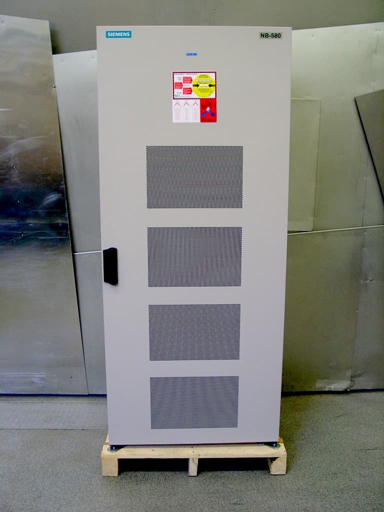
NE3PCS100
Jun 09, 20051900 MHz CAT40, DUAMCO
Equipment Class
PCB - PCS Licensed Transmitter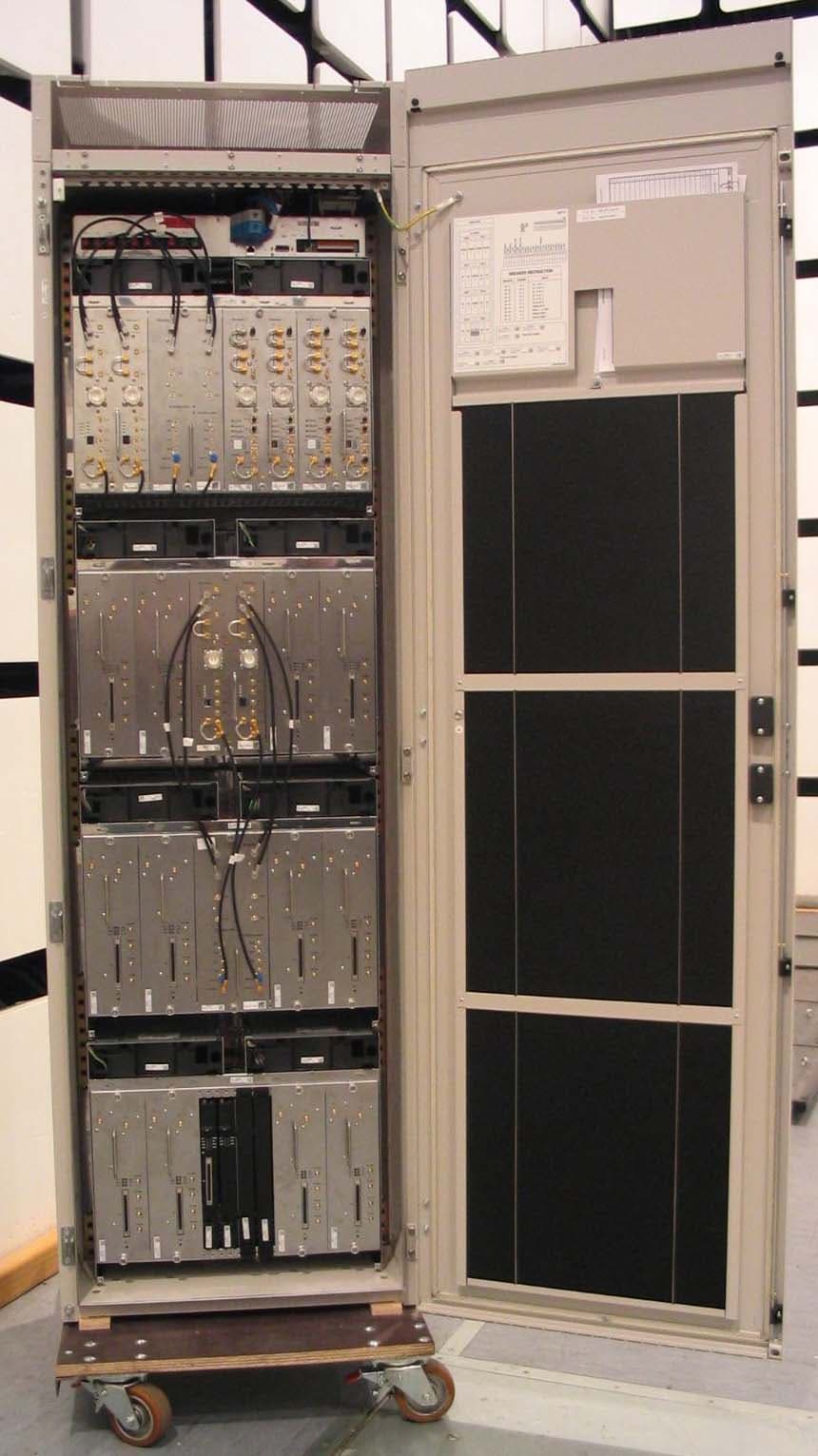
NE3PCS011
Mar 08, 20051900MHz FLEXCU AND FDUAMCO
Equipment Class
PCB - PCS Licensed Transmitter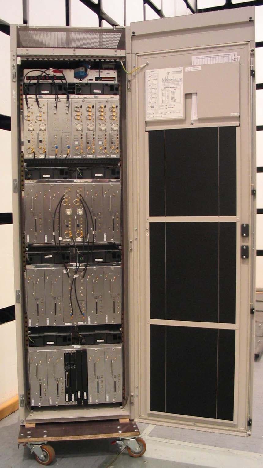
NE3PCS010
Mar 08, 2005850MHz FLEXCU AND FDUAMCO
Equipment Class
TNB - Licensed Non-Broadcast Station Transmitter
NE3PCS009
Dec 08, 2002High Power 1900 MHz Edge CU
Equipment Class
PCB - PCS Licensed Transmitter