NEO-DFR-LTE-3380DR3307 700MHz Booster
PBE Europe Ltd. trading as Axell Wireless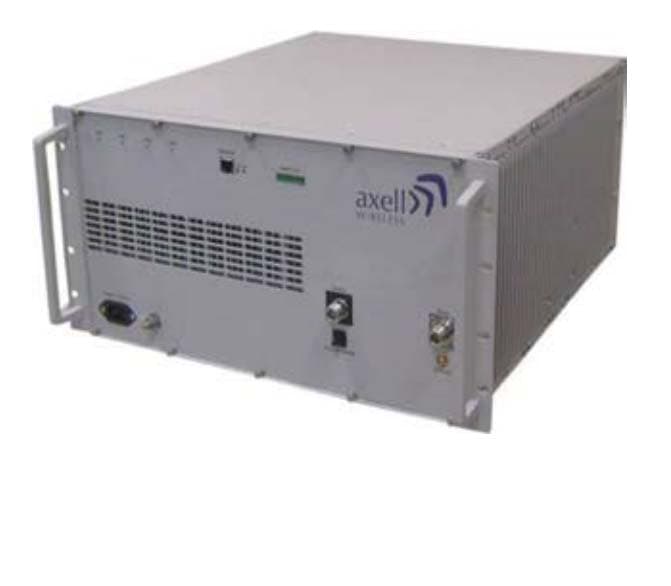
Click to zoom
Application Details
- Equipment Class
- AMP - Amplifier
- Date of Grant
- Nov 22, 2011
- Application Purpose
- Original Equipment
- Date of Application
- Nov 22, 2011
- Equipment Note
- DR3307 700MHz Booster
- Frequency Range
- 776.00000000 - 787.00000000
- Country
- United Kingdom
Documents & Files
Document Text
Text extracted from the exhibit documents filed with the FCC. Open a document above to read the original.
Users Manual
AXELL D-MBR-USA-USA REPEATER PRODUCT DESCRIPTION AND USER’S MANUAL High Selectivity Digital Multi-Band Repeater Product Description and User’s Manual for Axell D-MBR-USA 700LTE/850CELL/1700AWS/1900PCS REPEATER AXELL D-MBR-USA PRODUCT DESCRIPTION AND USER’S MANUAL II Axell Wireless Ltd Copyright © 2011 Axell Wireless Ltd All rights reserved. No part of this document may be copied, distributed, transmitted, transcribed, stored in a retrieval system, or translated into any human or computer language without the prior written permission of Axell Wireless Ltd. The manufacturer has made every effort to ensure that the instructions contained in this document are adequate and free of errors and omissions. The manufacturer will, if necessary, explain issues which may not be covered by this document. The manufacturer's liability for any errors in the document is limited to the correction of errors and the aforementioned advisory services. This document has been prepared to be used by professional and properly trained personnel, and the customer assumes full responsibility when using them. The manufacturer welcomes customer comments as part of the process of continual development and improvement of the documentation in the best way possible from the user's viewpoint. Please submit your comments to the nearest Axell Wireless sales representative. Contact Information Headquarters Axell Wireless Aerial House Asheridge Road Chesham Buckinghamshire HP5 2QD United Kingdom Tel: +44 1494 777000 Fax: +44 1494 777002 Commercial inquiries [email protected] Web site www.axellwireless.com Support issues [email protected] Technical Support Line, English speaking +44 1494 777 777 Contact information for Axell Wireless offices in other countries can be found on our web site, www.axellwireless.com REPEATER AXELL D-MBR-USA PRODUCT DESCRIPTION AND USER’S MANUAL © Axell Wireless Ltd III About This Manual This Product Manual provides the following information: • Description of the Repeater • Procedures for setup, configuration and checking the proper operation of the Repeater • Maintenance and troubleshooting procedures For whom it is Intended This Product Manual is intended for experienced technicians and engineers. It is assumed that the customers installing, operating, and maintaining Axell Wireless Repeaters are familiar with the basic functionality of Repeaters. Notice Confidential - Authorized Customer Use This document may be used in its complete form only and is solely for the use of Axell Wireless employees and authorized Axell Wireless channels or customers. The material herein is proprietary to Axell Wireless. Any unauthorized reproduction, use or disclosure of any part thereof is strictly prohibited. All trademarks and registered trademarks are the property of their respective owners. Disclaimer of Liability Contents herein are current as of the date of publication. Axell Wireless reserves the right to change the contents without prior notice. The information furnished by Axell Wireless in this document is believed to be accurate and reliable. However, Axell Wireless assumes no responsibility for its use. In no event shall Axell Wireless be liable for any damage resulting from loss of data, loss of use, or loss of profits and Axell Wireless further disclaims any and all liability for indirect, incidental, special, consequential or other similes damages. This disclaimer of liability applies to all products, publications and services during and after the warranty period. Safety Warnings and Admonishments Throughout this manual, important safety warnings and admonishments are included to warn of possible hazards to persons or equipment. A safety warning identifies a possible hazard and then describes what may happen if the hazard is not avoided. The safety warnings – in the form of Dangers, Warnings and Cautions must be followed at all times. These warnings are flagged by the use of a warning icon, usually the triangular alert icon seen below. The exclamation point within the triangular alert icon is intended to warn the operator or service personnel of operation and maintenance from factors relating to the product and its operating environment, which could pose a safety hazard. REPEATER AXELL D-MBR-USA PRODUCT DESCRIPTION AND USER’S MANUAL IV Axell Wireless Ltd General Safety Warnings Concerning Use of This System Always observe standard safety precautions during installation, operation and maintenance of this product. Only a qualified and authorized personnel should carry out adjustment, maintenance or repairs to the components of this equipment. Danger: Electrical Shock To prevent electrical shock when installing or modifying the system power wiring, disconnect the wiring at the power source before working with un insulated wires or terminals. Caution: RF Exposure Installation of an antenna must comply with the FCC RF exposure requirements. Exclusive Remedies The remedies provided herein are the Buyer’s sole and exclusive remedies. Axell Wireless shall not be viable for any direct, incidental, or consequential damages, whether based on contract, tort, or any legal theory. AXELL D-MBR-USA-USA REPEATER PRODUCT DESCRIPTION AND USER’S MANUAL Axell Wireless Ltd V Table of Contents 1 Introduction ................................................................................................................ 1 1.1 Features ................................................................................................................................ 2 1.2 Models and Ordering Information ...................................................................................... 3 1.3 Smart-ALC Function ............................................................................................................ 4 1.4 Axell D-MBR-USA Interfaces ............................................................................................... 5 1.5 Modem Support ....................................................…
Text truncated - open the document above for the full version.
Block Diagram
Figure 1: DMBR S implified Block Diagram
ID Label/Location Info
11 22 33 44 55 66 77 88 99 1010 1111 1212 A A B B C C D D E E F F G G H H A1 Drawing No Title First AngleProjection Drawn Date Checked Approved THIS IS A PROPRIETARY DESIGN OF AXELL WIRELESS LTDREPRODUCTION OR USE OF THIS DESIGN BY OTHER ISPERMISSABLE ONLY IF EXPRESSLY AUTHORISED IN WRITINGBY AXELL WIRELESS LTD GENERAL TOLERANCES SCALE ALL DIMENSIONS ARE IN mmUNLESS OTHERWISE STATED REVISION No DESCRIPTION DATE BY UNLESS STATED OTHERWISE ISO 2768-1 MEDIUM 2010-05-14 PerW 2010-05-14 PerW 2010-05-14 A PerW Tel : +46 (0)8 475 4700Fax : +46 (0)8 475 4799 Sheet 3 / 3 Rev. 20.00 3 2 . 0 0 VERIZON REPEATER 400AA21000
ID Label/Location Info
A 4 Drawing Number Title First Angle Projection Drawn Date Checked Approved Scale THIS IS A PROPRIETARY DESIGN OF AXELL WIRELESS LTD REPRODUCTION OR USE OF THIS DESIGN BY OTHERS IS PERMISSABLE ONLY IF EXPRESSLY AUTHORISED IN WRITING BY AXELL WIRELESS LTD. REVISIONNo DATE BY GENERAL TOLERANCES ISO 2768-1 MEDIUM 2009-04-28 PerWPerW 2010-08-24 2010-08-24 A 2:1 PerW ALL DIMENSIONS ARE IN mm UNLESS OTHERWISE STATED Tel : +46 (0)8 475 4700 Fax : +44 (0)8 475 4799 UNLESS STATED OTHERWISE Sheet 1 / 1 Rev. NOTE. 1. MATERIAL: SHEET SILVER COLOR METALIZED POLYESTER WITH ONE SIDE WITH 3M 467MP BACK ADHESIVE + ADHESIVE 200MP ON ONE SIDE. 2. PRINTING 2.1 BACKGROUND "a": SILVER 2.2 SYMBOLS AND FONTS "b" : BLACK 2.3 FONTS: HELVETICA MEDIUM 3. USE RIBBON ACCORDING TO LABEL MANUFACTURER RECOMENDATION. 4. FOR SERIAL NUMBER SEE LABEL INFORMATION. 5. BAR CODE TYPE ACCORDING TO CODE-128 6. THE LABELS MUST BE SUPPLIED ON ROLL. 7. PART MUST COMPLY RoHS REQUIREMENTS. 8. LABEL INFORMATION: YY-Year (2 Digits) MM- Month (2 Digits) ZZZZZZ- Serial No. 76.20 3 8 . 1 0 AXELL35781719D S/N LABEL
Internal Photos
DMBR Internal Photographs Internal Internal ban d Module CCD Bottom CCD TOP Modem on CCD Power Supply 700MHz Amplifier Top 700MHz Amplifier Bottom Internal Photographs – DMBR Page 1 of 2 850MHz Amplifier Top 850MHz Amplifier Botto m RF Top RF Bottom Digital Top Digital Bottom Internal Photographs – DMBR Page 2 of 2
Operational Description
mULTI-BAND COVERAGE SOLUTIONS The new Digital Multi-Band Repeater (D-MBR) from Axell Wireless is a flexible, multi-band coverage solution optimised for in-building applications. The D-MBR is based on the Axell Wireless’ innovative digital filtering technology (DSP) which supports current and future frequency allocations. Up to four different frequency bands can be implemented in one repeater casing. The solution can be equipped with modules covering the 700MHz, 850MHz, 1700MHz and 1900MHz D-mBR - Americas Digital multi-Band Repeater Designed to meet North American frequency requirements Up to four frequency bands in one compact enclosure Software Defined Filtering of up to 12 sub-bands in each frequency band Band modules for 700MHz (LTE), 850MHz (Cellular), 1700MHz (AWS) and 1900MHz (PCS) Individual gain and ALC settings for each sub-band for single and multi-operator applications Ideal for flexible In-building applications Complies with TS 36.106 (LTE) and TS 25.106 (WCDMA) standards Supports 700MHz upper and lower bands simultaneously bands. For each frequency band, the D-MBR can provide selection and amplification of up to 12 sub bands of programmable bandwidth with the new software defined filtering module. Using an advanced ALC mechanism each one of the sub bands has an individual gain and ALC setting. The Digital Mulit-band repeater has a separate module per each frequency band. This architecture allows redundancy, i.e. failure in one of the band modules will not have any impact on the other band modules. A dedicated DSP per band allows the support of full bandwidth per each band without any limitation. The D-MBR is connected to one donor antenna placed on the roof of the building and the radiating coaxial cable or antennas in the area to be covered. Configuration and monitor- ing of the D-MBR can be done through an intuitive web management GUI, either locally or remotely via a wireless modem. With the Axell Wireless advanced supervision and control software, the entire fleet of digital multi-band repeaters can be monitored. Axell Wireless D-MBR repeater is powerful enough to drive a passive Distributed Antenna system (DAS) for coverage areas over 100,000 ft 2 (10,000m 2 ) in buildings, parking lots, malls, warehouses and offices. Page 1 of 3 RADIo MoDULE FoR 700 MHz UPLINkDoWNLINk operating Frequency Range Lower band Upper band 698-716MHz 776 - 787MHz 728-746MHz 746-757MHz output power at antenna port (composite) 27dBm33dBm Pass band maximum gain82dB82dB Gain attenuation range0-25dB (in 1dB steps)0-25dB (in 1dB steps) Pass band ripple± 25dB± 25dB Noise Figure @ max gain4dB5dB Propagation delay< 6 μsec< 6 μsec Number of filters (*)1 to 12 or 1 to 81 to 12 or 1 to 8 RADIo MoDULE FoR 850 MHz (CELLULAR) operating Frequency Range824-849MHz869-894MHz output power at antenna port (composite) 27dBm33dBm Pass band maximum gain82dB82dB Gain attenuation range0-25dB (in 1dB steps)0-25dB (in 1dB steps) Pass band ripple± 2.5dB± 2.5dB Noise Figure @ max gain3.5dB5dB Propagation delay< 6 μsec< 6 μsec Number of filters (*)1 to 12 or 1 to 81 to 12 or 1 to 8 RADIo MoDULE FoR 1700 MHz (AWS) operating Frequency Range1710-1755MHz2110-2155MHz output power at antenna port (composite)27dBm30dBm Pass band maximum gain82dB82dB Gain attenuation range0-25dB (in 1dB steps)0-25dB (in 1dB steps) Pass band ripple± 2.5dB± 2.5dB Noise Figure @ max gain3.5dB5dB Propagation delay< 6 μsec< 6 μsec Number of filters (*)1 to 12 or 1 to 81 to 12 or 1 to 8 RADIo MoDULE FoR 1900MHz operating Frequency Range1850-1910 MHz1930-1990MHz output power at antenna port (composite)27dBm30dBm Pass band maximum gain82dB82dB Gain attenuation range0-25dB (in 1dB steps)0-25dB (in 1dB steps) Pass band ripple ± 2.5dB± 2.5dB Noise Figure @ max gain3.5dB5dB Propagation delay< 6 μsec< 6 μsec Number of filters (*)1 to 12 or 1 to 81 to 12 or 1 to 8 ELECTRICAL SPECIFICATIoN Power Supply110/240 VAC Power Consumptionmax 320W for 3 bands, max 400W 4 bands ENVIRoNMENTAL SPECIFICATIoN Operating Temperature Range14°F to 122°F (-10°C to +50°C) Complies with FCC, UL Humidity85% MTBF, complete system >70 000 hrs MECHANICAL SPECIFICATIoN Dimensions: 19” x 5U rack x 19.7” (b x h x d), 450 x 225 x 500 mm, Weight:77 lbs (35 kg) for 3 bands, 86 lbs (39 kg) for 4 bands CoMPLIANCE RadioFCC ALL PARAMETERS ARE TYPICAL AT +77°F (+25°C). SPECIFICATIoNS ARE SUBJECT To CHANGE WITHoUT NoTICE (*) Supports BW option up to 20 MHz by setting the start-stop frequency Page 2 of 3 SpECIfICATIONS About Axell Wireless Axell Wireless is one of the top 3 global providers of wireless coverage solutions and the market leader in the provision of solutions for the public safety market worldwide. Applications for Axell Wireless equipment include coverage solutions for all sorts of environments including road and rail tunnels, metros, small and large buildings and transportation systems such as railways and aeroplanes. With its headquarters in the Uk, Axell Wireless has been operating for over 30 years and has a substantial international presence operating out of 10 offices across 4 continents. A proven track record combined with a worldwide reputation for providing innovative and high quality products have made Axell Wireless a truly global player in the wireless coverage industry. www.axellwireless.com D-MBR _rev N_USA • © Axell Wireless Ltd IdentificationDescription partNumber D-MBR kit 700/850/1700/1900 Quad Band kit 700/850/AWS/PCS, 8 filters per band, CDMA 1x modemDR3307-30-81719 D-MBR kit 700/850/1700/1900 Quad Band kit 700/850/AWS/PCS, 12 filters per band, CDMA 1x modemDR3307-30-81719-12 D-MBR kit 700/850/1900Tri Band kit 700/850/PCS, 8 filters per band, CDMA 1x modemDR3307-30-819 D-MBR kit 700/850/1900 TriBand kit 700/850/PCS, 12 filters per band, CDMA 1x modemDR3307-30-819-12 D-MBR kit 700/850/1900 TriBand kit 700/850/PCS, 8 filters, 9 Plexer for AWS, CDMA 1x modemDR27-78-3019 D-MBR kit 700/850/1900TriBand kit 700/850/PCS, 12 filters, 9 Plexer for AWS, CDMA 1x modemDR27-78-30…
Text truncated - open the document above for the full version.
Test Report
RADIO TEST REPORT FOR AXELL WIRELESS ON DR3307-3308 DIGITAL MULTI-BAND REPEATER DOCUMENT NO. TRA-007383-01-W-US1 TEST REPORT NO: TRA-007383-01-W-US1 COPY NO: 1 ISSUE NO: 1 FCC ID: NEO-DFR-LTE-3380 REPORT ON THE CERTIFICATION TESTING OF A AXELL WIRELESS DR3307-3308 DIGITAL MULTI-BAND REPEATER WITH RESPECT TO THE FCC RULES CFR 47, PART 22 TEST DATE: 21 st - 28 th October 2011 APPROVED BY: J CHARTERS RADIO PRODUCT MANAGER DATE: 21 st November 2011 Distribution: Copy Nos: 1. Axell Wireless 2. TRaC Global THIS DOCUMENT MAY BE REPRODUCED ONLY IN ITS ENTIRETY AND WITHOUT CHANGE TRA-007383-01-W-US1 Page 3 of 80 CONTENTS PAGE CERT IFICATE OF CONFORMITY & COMPLIANCE 4 APPLICANT’S SUMMARY 5 EQUIPMENT TEST CONDITIONS 6 TESTS REQUIRED 6 TEST RESULTS 7 – 94 ANNEX PHOTOGRAPHS A APPLICANT’S SUBMISSION OF DOCUMENTATION LIST B EQUIPMENT CALIBRATION C MEASUREMENT UNCERTAINTY D Notes: 1. Component failure during test YES NO [ ] [X] 2. If Yes, details of failure: 3. The facilities used for the testing of the product contain in this report are FCC Listed. CERTIFICATE OF CONFORMITY & COMPLIANCE TRA-007383-01-W-US1 FCC IDENTITY: NEO-DFR-LTE-3380 PURPOSE OF TEST: Certification TEST SPECIFICATION: FCC RULES CFR 47, Part 22 TEST RESULT: Compliant to Specification EQUIPMENT UNDER TEST: DR3307-3308 Digital Multi-Band Repeater EQUIPMENT TYPE: Private Land Mobile Repeater MAXIMUM GAIN: Uplink Downlink = 71.44 dB = 80.72 dB MAXIMUM INPUT: Uplink Downlink = -48 dBm = -47 dBm MAXIMUM OUTPUT CONDUCTED: Uplink Downlink = 23.18 dBm = 33.46 dBm NUMBER OF CHANNELS: Software selectable between 1 and 12 CHANNEL BANDWIDTH: Upto 20MHz per single channel, programmable FREQUENCY GENERATION: N/A MODULATION TYPE: LTE POWER SOURCE(s): +110Vac TEST DATE(s): 21 st - 28 th October 2011 APPLICANT: Axell Wireless ADDRESS: Aerial House Asheridge Road Chesham Buckinghamshire HP5 1TU TESTED BY: S. BHARAT APPROVED BY: J. CHARTERS RADIO PRODUCT MANAGER TRA-007383-01-W-US1 Page 5 of 80 APPLICANT’S SUMMARY EQUIPMENT UNDER TEST (EUT): DR3307-3308 Digital Multi-Band Repeater EQUIPMENT TYPE: Private Land Mobile Repeater PURPOSE OF TEST: Certification TEST SPECIFICATION(s): FCC RULES CFR 47, Part 90 TEST RESULT: COMPLIANT Yes No [X] [ ] APPLICANT’S CATEGORY: MANUFACTURER IMPORTER DISTRIBUTOR TEST HOUSE AGENT [X] [ ] [ ] [ ] [ ] APPLICANT’S CONTACT PERSON(s): Mr Peter Bradfield E-mail address: [email protected] APPLICANT: Axell Wireless ADDRESS: Aerial House Asheridge Road Chesham Buckinghamshire HP5 1TU United Kingdom TEL: +44 (0)1494 777000 FAX: +44 (0)1494 778456 MANUFACTURER: Axell Wireless EUT(s) COUNTRY OF ORIGIN: United Kingdom TEST LABORATORY: TRaC Global TEST DATE(s): 21 st - 28 th October 2011 TEST REPORT No: TRA-007383-01-W-US1 TRA-007383-01-W-US1 Page 6 of 80 EQUIPMENT TEST / EXAMINATIONS REQUIRED 1. TEST/EXAMINATION RULE PART APPLICABILITY RESULT RF Power Output 27.50 Yes Complies Audio Frequency Response TIA EIA-603.3.2.6 N/A N/A Audio Low-Pass Filter Response TIA EIA-603.3.2.6 N/A N/A Modulation Limiting TIA EIA-603.3.2.6 N/A N/A Occupied Bandwidth 27.53 Yes Complies Spurious Emissions at Antenna Terminals 27.53 Yes Complies Field Strength of Spurious Emissions 27.53 Yes Complies Frequency Stability 27.54 N/A(note 1) N/A Transient behaviour N/A N/A(note 2) N/A Notes: 1 The EUT does not contain modulation circuitry, therefore the test was not performed. 2 The EUT is not a keyed carrier system, therefore the test was not performed. Uplink Class A [ ] Class B [X] 2. Product Class: Downlink Class A [ ] Class B [X] 3. Product Use: Private Land Mobile Repeater 4. Emission Designator: F9W 5. Temperatures: Ambient (Tnom) 22 o C 6. Supply Voltages: Vnom +110Vac Note: Vnom voltages are as stated above unless otherwise shown on the test report page Single channel [ ] Two channel [ ] 7. Equipment Category: Multi-channel [X] 8. Channel spacing: Narrowband Uplink Narrowband Downlink 9. Test Location TRaC Global Skelmersdale [X] Hull [ ] 10. Modifications made during test program No modifications were performed. System description: The Digital Multi-Band Repeater is a Private Land Mobile Repeater designed to meet North American requirements. In the 700MHz LTE band, the uplink operates over 698MHz to 716MHz and 776MHz to 787MHz. Downlink operates over 728MHz to 757MHz. There are up to 12 programmable sub bands. Each sub band can be set to a maximum of 20MHz wide by setting start and stop frequencies. TRA-007383-01-W-US1 Page 7 of 80 COMPLIANCE TESTS AMPLIFIER GAIN – CONDUCTED – UPLINK Ambient temperature = 22 o C Radio Laboratory Relative humidity = 43% Supply voltage = +110Vac Channel number = See test results The EUT was set up as shown above. The signal generator level was increased in steps of 1dB till compression point was reached, wherein there was no corresponding increase in output for a known increase in input. The level on the signal generator was noted along with the output level. The input was then increased by 10dB and the corresponding output level was recorded. The system was calibrated for any losses, the gain and output power were calculated and produced below. Results: Frequency (MHz) Signal Generator input level (dBm) Input Cable Loss (dB) Output Cable & Attenuator loss (dB) Level at Spectrum Analyser (dBm) Gain (dB) Conducted Output Power (dBm) Gain after 10dB input level increase (dB) 698.7 -46 0.23 30.39 -7.71 68.91 22.68 58.94 707.0 -48 0.26 30.41 -7.23 71.44 23.18 61.48 715.3 -48 0.23 30.40 -8.58 70.05 21.82 60.06 776.7 -49 0.23 30.38 -9.29 70.32 21.09 60.41 781.5 -48 0.22 30.40 -8.82 69.80 21.58 59.83 786.3 -48 0.29 30.40 -8.51 70.18 21.89 60.21 Notes: 1. The signal generator input was increased by 10dB and the level of the output signal was remeasured 2. The smallest filter (1.4MHz wide) was opened and a carrier was passed at the centre of each filter Test equipment used: Type Of Equipment Maker/ Supplier Model No Serial No TRaC Ref No Actual Equipment Used Spectrum Analyser Rohde & Schwarz FSU46 100021/046 UH2…
Text truncated - open the document above for the full version.
Test Setup Photos
Photograph 1: Radiated test setup Photograph 2: Conducted test setup
Contact Information
Applicant
Michael Adam Godsey(VP of Design Engineering)
Test Firm
Element Materials Technology Warwick LtdKeith Wright
Technical Specifications
| # | Rule Parts | Frequency Range | Power Output | Emission | Tolerance |
|---|---|---|---|---|---|
| 4 | 27 | 776 MHz - 787 MHz | 150.00 mW | F9W | Amp |
Other Applications from PBE Europe Ltd. trading as Axell Wireless

NEO61-105SERIES
Nov 27, 2022BSF3604
Equipment Class
B9B - Part 90 Class B Industrial Booster (non-SMR)
NEOA218DSERIES
Jul 14, 2022MBF-37D7-3708
Equipment Class
B2I - Part 20 Industrial Booster (CMRS)
NEO36IDRU420
May 06, 2020Class B Booster
Equipment Class
B9B - Part 90 Class B Industrial Booster (non-SMR)
NEODMBR37073708PS
Jan 04, 2016Class B Booster
Equipment Class
B9B - Part 90 Class B Industrial Booster (non-SMR)
NEODMBA30073008PS
Aug 30, 2015Class A Booster
Equipment Class
B9A - Part 90 Class A Industrial Booster (non-SMR)