NEO36IDRU420Class B Booster
PBE Europe Ltd. trading as Axell Wireless
Click to zoom
Application Details
- Equipment Class
- B9B - Part 90 Class B Industrial Booster (non-SMR)
- Date of Grant
- May 06, 2020
- Application Purpose
- Original Equipment
- Date of Application
- May 05, 2020
- Equipment Note
- Class B Booster
- Frequency Range
- 426.36300000 - 428.07500000
- Country
- United Kingdom
Documents & Files
Document Text
Text extracted from the exhibit documents filed with the FCC. Open a document above to read the original.
Users Manual
Doc. No. 00109GU Rev. 2.0 cobhamwireless.com idDAS Installation and Maintenance Guide Cobham Wireless idDAS Installation and Maintenance Guide 00109GU Rev. 2.0 Page | II Preface Material Copyright © 2020 Axell Wireless Limited trading as Cobham Wireless All rights reserved. No part of this document may be copied, distributed, transmitted, transcribed, stored in a retrieval system, or translated into any human or computer language without the prior written permission of Axell Wireless Limited trading as Cobham Wireless. The manufacturer has made every effort to ensure that the instructions contained in this document are adequate and free of errors and omissions. The manufacturer will, if necessary, explain issues which may not be covered by this document. The manufacturer's liability for any errors in the document is limited to the correction of errors and the aforementioned advisory services. This document has been prepared to be used by professional and properly trained personnel, and the customer assumes full responsibility when using them. The manufacturer welcomes customer comments as part of the process of continual development and improvement of the documentation in the best way possible from the user's viewpoint. Please submit your comments to the nearest Cobham Wireless sales representative. Notice Confidential - Authorized Customer Use This document may be used in its complete form only and is solely for the use of Cobham Wireless employees and authorized Cobham Wireless channels or customers. The material herein is proprietary to Cobham Wireless. Any unauthorized reproduction, use or disclosure of any part thereof is strictly prohibited. All trademarks and registered trademarks are the property of their respective owners. Disclaimer of Liability Contents herein are current as of the date of publication. Cobham Wireless reserves the right to change the contents without prior notice. The information furnished by Cobham Wireless in this document is believed to be accurate and reliable. However, Cobham Wireless assumes no responsibility for its use. In no event shall Cobham Wireless be liable for any damage resulting from loss of data, loss of use, or loss of profits and Cobham Wireless further disclaims any and all liability for indirect, incidental, special, consequential or other similes damages. This disclaimer of liability applies to all products, publications and services during and after the warranty period. Contact Information Headquarters Axell Wireless trading as Cobham Wireless The Cobham Centre, Fourth Avenue, MARLOW, Buckinghamshire, SL7 1TF United Kingdom Tel: +44 1494 777000 Website www.cobhamwireless.com Support issues [email protected] Technical Support Line, English speaking +44 1494 777 747 Cobham Wireless idDAS Installation and Maintenance Guide 00109GU Rev. 2.0 Page | III About this Manual and for whom it is Intended This Installation Guide is intended for experienced technicians and engineers. It is assumed that the customers installing, operating, and maintaining Cobham Wireless equipment are familiar with the basic functionality of this type of equipment. It provides the following information: x Description of the idDAS System Elements x Installation requirements x Procedures for installations of various configurations x Maintenance procedures x Specifications x Ordering information Revision History REV ECO DETAILS Rev. 1.3 C12145 x Maintenance procedures updates: MTDI chassis, idRU30, idRU40, MSDH, APOI, instructions for required web GUI operations x Updated APOI to MTDI connections x Updates on idRU external alarms connections x High Power idRU 1800 composite output power specs with and without GSM x Factory set static IP Address 192.168.1.253 x New Public safety idRU 30dBm x Ordering information updated and includes Eng. Numbers x Input for DC powered units =36 to 60V DC x Circuit breaker Type-C 10A required for idRU0036 x LEDs updated x Height dimension of MSDH for Americas PS DC = 350mm x RF source redundancy driven topology x Master Slave topology 2.0 C12559 x Full system redundancy updates and public safety alarms x RF exposure warning on minimum safe distance for the idRU ‘id-DAS-RRU-3707 - 3708-PS-NFPA-DC’ x Safe distance update for id-DAS-RRU-3604-PS-NFPA-AC, RRU0042 Cobham Wireless idDAS Installation and Maintenance Guide 00109GU Rev. 2.0 Page | IV General Warnings Required Permissions and Licenses Prior to the use of this equipment, the user must ensure they have the permissions and licenses required for the intended transmissions. Safety Instructions and Warnings Throughout this manual, important safety warnings and admonishments are included to warn of possible hazards to persons or equipment. A safety warning identifies a possible hazard and then describes what may happen if the hazard is not avoided. The safety warnings – in the form of Dangers, Warnings and Cautions must be followed at all times. These warnings are flagged by the use of a warning icon, usually the triangular alert icon seen below. The exclamation point within the triangular alert icon is intended to warn the operator or service personnel of operation and maintenance from factors relating to the product and its operating environment, which could pose a safety hazard. Guarantees All antennas must be installed with lightning protection. Damage to power modules, as a result of lightning are not covered by the warranty. Switching on AC or DC power prior to the connection of antenna cables is regarded as faulty installation procedure and therefore not covered by the Cobham Wireless warranty. Repeater enclosures should be closed using the two screws. The screws must be fully tightened. Failure to do so may affect the IP66 compliancy and therefore any warranty. Unauthorized Changes to Equipment Changes or Modifications not expressly approved by Cobham Wireless could void the user’s authority to operate the equipment. Exclusive Remedies The remedies provided herein are the Buyer’…
Text truncated - open the document above for the full version.
Cover Letter(s)
Axell Wireless Ltd. IC:8749A-36IDRU420 FCC ID:NEO36IDRU420 idRU IC Compliance Warning Direct connection of antenna to the SERV/MOB port is not permitted. To ensure that the noise and spurious emissions levels meet the limits defined in RSS-131 for the ‘id‐DAS‐RRU‐3707‐3708‐PS‐NFPA‐DC’ the following conditions must be met on installation. -6dBd Antenna Gain Assembly Antenna Assembly Gain[dBd] = Gain Antenna[dBi] – 2.15 – Loss of cables/splitters[dB] ≤ -6dB Conformité du répéteur idRU aux normes d'Industrie Canada Avertissement La connexion directe de l’antenne au port SERV/MOB n’est pas autorisée. Pour s’assurer que les niveaux de PAR (Puissance Apparente Rayonnée) restent dans les limites définies par le CNR-131 pour le répéteur « id‐DAS‐RRU‐3707‐3708‐PS‐NFPA‐DC », les conditions suivantes doivent être remplies lors de l’installation. Gain de l’ensemble antenne -6dBd Gain de l’ensemble antenne [dBd] = Gain de l’antenne[dBi] – 2.15 – Perte des câbles/diviseurs [dB] ≤ -6dB
Cover Letter(s)
Axell Wireless Limited trading as Cobham Wireless Axell Wireless Limited trading as Cobham Wireless Registered in England and Wales: 04042808 Registered Office: C/O Cobham plc, Brook Road, Wimborne, Dorset, BH21 2BJ, UK www.cobham.com/wireless Subject: Application for certification of the Class B Booster (Intelligent Digital DAS UHF Public Safety idRU), FCC ID:NEO36IDRU420 To whom it may concern Axell Wireless Limited, hereby declares that the respective warning labels and class B disclosure will be shown in all relevant online and point-of-sale marketing material and also on the outside of packaging for the device. Sincerely yours, Brian Barton, Operations Support Director Axell Wireless Ltd. Axell Wireless Limited trading as Cobham Wireless Cobham Wireless The Cobham Centre, Fourth Avenue, Marlow, Bucks, SL7 1TF, England. T: +44 1494 777 000 F: +44 1494 777 002
Cover Letter(s)
Axell Wireless Limited trading as Cobham Wireless Registered in England and Wales: 04042808 Registered Office: C/O Cobham plc, Brook Road, Wimborne, Dorset, BH21 2BJ, UK www.cobham.com/wireless Declaration of Authorization We Name: Axell Wireless Limited Address: The Cobham Centre, Fourth Avenue City: Marlow, Bucks SL7 1TF Country: United Kingdom Declare that: Name Representative of agent: Michael Nikishin Agent Company name: Hermon Laboratories Ltd. Address: Harakevet Industrial Zone, City: Binyamina 30500, Country Israel. is authorized to apply for Certification of the following product(s): Product description: Class B booster (idDAS UHF Public Safety idRU) Type designation: id-DAS-RRU-3604-PS-NFPA-AC Trademark: Cobham Wireless Validity/ expiry date: 20 th April 2021 on our behalf. Date: 20 th April 2020 City: Marlow Name: Brian Barton Function: Operations Support Director Signature: Cobham Wireless The Cobham Centre, Fourth Avenue, Marlow, Bucks, SL7 1TF, England. T: +44 1494 777 000 F: +44 1494 777 002
Cover Letter(s)
FCC, Request for non-disclosure Date: 19-Oct-10 RF_501, Issue 7 Page 1 of 1 Company Name: Axell Wireless Limited Address: The Cobham Centre, Fourth Avenue, City: Marlow, Buckinghamshire, SL7 1TF, Country: United Kingdom To: Telefication B.V., Dept. FCC TCB Edisonstraat 12A 6902 PK ZEVENAAR The Netherlands Subject: Request for confidentiality FCC ID: NEO36IDRU420 Reference number: ###### Dear FCC TCB, 1. Long-Term Confidentiality Pursuant to 47 CFR Section 0.459(a) & (b), we hereby requests non-disclosure and confidential treatment of the following materials submitted in support of FCC certification application: Bill(s) of Material Block Diagrams Operational Description Schematic Diagrams Tune-up Procedure Above materials contain secrets, proprietary and technical information, which would customarily be guarded from competitors under 47 CFR, section 0.457(d)(2). Disclosure or publication or any portion of this company confidential material to other parties could cause substantial competitive harm and provide unjustified benefits for competitors. 2. Short-Term Confidentiality (STC) Pursuant to Public Notice DA 04-1705 of the Commission’s policy, in order to comply with the marketing regulations in 47 CFR §2.803 and the importation rules in 47 CFR §2.1204, applicant hereby requests Short-Term Confidential treatment of the following materials (note 1): Internal Photos User’s Manual Test Set-up Photos External Photos Justification: Axell Wireless Limited. is requesting the internal photos be permanently confidential. This non- consumer device is inaccessible to the general public, and shall be kept in a secured and locked environment. Further, Axell Wireless Limited is requesting the Operational Description and User Manual (the Documents referenced below) be permanently confidential. The reason for this request is that the Documents are of a technical nature and are not provided to the consumer because the consumer cannot service the device. Our devices will be sold to a limited audience and the COBHAM wishes the Documents to be inaccessible to the general public at all times. Appropriate documentation will be made be available only to Axell Wireless Limited partners and integrators only. Designated professionals under the employ of these partners and integrators will be responsible for service and maintenance of our devices. Each partner and integrator will be under a non-disclosure agreement with Axell Wireless Limited FCC, Request for non-disclosure Date: 19-Oct-10 RF_501, Issue 7 Page 1 of 1 Planned Release Date STC: 180 days after grant date (notes 2, 3, 4, 5). If no date is given, 45 days from grant date will be used. Date: 30 th October 2019 Name and signature of applicant: Brian Barton Notes: 1) A document or type of document can only have ONE type of confidentiality! 2) Short-Term confidentiality is in principle for 45 days from date of grant; it can be extended max 3 times (total time 180 days max.)! 3) FCC must be informed when marketing begins earlier. 4) Release takes place automatically thus extension must be requested in time. Telefication does not remind you of this! 5) Request for extension or for release must be received by Telefication at least 7 days before date of actual marketing or before expiration of the STC period
External Photos
Axell Wireless Ltd. FCC ID:NEO36IDRU420 IC:8749A-36IDRU420 Page 1 of 5 EXTERNAL PHOTOGRAPHS This document contains 4 photographs RRU0043 External photos Page 1 of 4 Cobham Wireless Cobham Private www.cobham.com/wireless RRU0043 External photos Page 2 of 4 Cobham Wireless Cobham Private www.cobham.com/wireless RRU0043 External photos Page 3 of 4 Cobham Wireless Cobham Private www.cobham.com/wireless RRU0043 External photos Page 4 of 4 Cobham Wireless Cobham Private www.cobham.com/wireless
ID Label/Location Info
Axell Wireless Ltd. FCC ID:NEO36IDRU420 IC:8749A-36IDRU420 Page 1 of 4 LABELS The labels are affixed on the EUT side panel as shown below. The label material is sheet silver color metalized polyester with a permanent adhesive. Label with FCC ID and IC number Warning label Axell Wireless Ltd. FCC ID:NEO36IDRU420 IC:8749A-36IDRU420 Page 2 of 4 Labels location Label with FCC ID:NEO36IDRU420 and IC:8749-36IDRU420 is located here. The FCC Warning label is located here. The ISED warning labels are located here. 1 1 2 2 3 3 4 4 5 5 6 6 AA BB CC DD GENERAL TOLERANCES 6/22/2017 Date Drawn UNLESS STATED OTHERWISE ISO 2768-1 MEDIUM THIS IS A PROPRIETARY DESIGN OF COBHAM WIRELESS REPRODUCTION OR USE OF THIS DESIGN BY OTHERS IS PERMISSABLE ONLY IF EXPRESSLY AUTHORISED IN WRITING BY COBHAM WIRELESS. Title Drawing Number Tel : +46 (0)8 475 4700 Fax : +44 (0)8 475 4799 Rev. A First Angle Projection Sheet A 3 IC Industrial Booster Warning Label 6/14/2016 ALL DIMENSIONS ARE IN mm UNLESS OTHERWISE STATED Scale 3:1 Ziv.S Approved Ziv.S Checked ISO 2768-2 H 6/14/2016 1 / 1 Ziv.Schwartz 9713002471 A 22.6.2017 Ziv.S REVISION HISTORY ZONEREVDESCRIPTIONDATEAPPROVED NOTE. 1. MATERIAL: SHEET SILVER COLOR METALIZED POLYESTER WITH ONE SIDE WITH 3M 467MP BACK ADHESIVE + ADHESIVE 200MP ON ONE SIDE. 2. PRINTING 2.1 BACKGROUND "a": SILVER 2.2 SYMBOLS AND FONTS "b" : BLACK 2.3 FONTS: HELVETICA MEDIUM 3. USE RIBBON ACCORDING TO LABEL MANUFACTURER RECOMENDATION. 4. THE LABELS MUST BE SUPPLIED ON ROLL. 5. PART MUST COMPLY ToHS REQUIREMENTS. 76.20 3 8 . 1 0 1 1 2 2 3 3 4 4 5 5 6 6 AA BB CC DD GENERAL TOLERANCES 7/6/2017 Date Drawn UNLESS STATED OTHERWISE ISO 2768-1 MEDIUM THIS IS A PROPRIETARY DESIGN OF COBHAM WIRELESS REPRODUCTION OR USE OF THIS DESIGN BY OTHERS IS PERMISSABLE ONLY IF EXPRESSLY AUTHORISED IN WRITING BY COBHAM WIRELESS. Title Drawing Number Tel : +46 (0)8 475 4700 Fax : +44 (0)8 475 4799 Rev. A First Angle Projection Sheet A 3 French IC Industrial Booster Warning Label 7/6/2017 ALL DIMENSIONS ARE IN mm UNLESS OTHERWISE STATED Scale 3:1 Ziv.S Approved Ziv.S Checked ISO 2768-2 H 7/6/2017 1 / 1 Ziv.Schwartz 9713002504 A 6.7.2017 Ziv.S REVISION HISTORY ZONEREVDESCRIPTIONDATEAPPROVED NOTE. 1. MATERIAL: SHEET SILVER COLOR METALIZED POLYESTER WITH ONE SIDE WITH 3M 467MP BACK ADHESIVE + ADHESIVE 200MP ON ONE SIDE. 2. PRINTING 2.1 BACKGROUND "a": SILVER 2.2 SYMBOLS AND FONTS "b" : BLACK 2.3 FONTS: HELVETICA MEDIUM 3. USE RIBBON ACCORDING TO LABEL MANUFACTURER RECOMENDATION. 4. THE LABELS MUST BE SUPPLIED ON ROLL. 5. PART MUST COMPLY ToHS REQUIREMENTS. 76.20 3 8 . 1 0
Internal Photos
Axell Wireless Ltd. FCC ID:NEO36IDRU420 IC:8749A-36IDRU420 Page 1 of 10 INTERNAL PHOTOGRAPHS This document contains 9 photographs RRU0043 Internal photos Page 1 of 9 Cobham Wireless Cobham Private www.cobham.com/wireless RRU0043 Internal photos Page 2 of 9 Cobham Wireless Cobham Private www.cobham.com/wireless RRU0043 Internal photos Page 3 of 9 Cobham Wireless Cobham Private www.cobham.com/wireless RRU0043 Internal photos Page 4 of 9 Cobham Wireless Cobham Private www.cobham.com/wireless RRU0043 Internal photos Page 5 of 9 Cobham Wireless Cobham Private www.cobham.com/wireless RRU0043 Internal photos Page 6 of 9 Cobham Wireless Cobham Private www.cobham.com/wireless RRU0043 Internal photos Page 7 of 9 Cobham Wireless Cobham Private www.cobham.com/wireless RRU0043 Internal photos Page 8 of 9 Cobham Wireless Cobham Private www.cobham.com/wireless RRU0043 Internal photos Page 9 of 9 Cobham Wireless Cobham Private www.cobham.com/wireless
RF Exposure Info
Axell Wireless Ltd. FCC ID:NEO36IDRU420 Page 1 of 1 Environmental evaluation and exposure limit according to FCC CFR 47part 1, §1.1307, §1.1310 The booster is classified as a fixed device, the calculation was done to confirm a safe distance. Limit for power density for general population/uncontrolled exposure is f/1500 mW/cm 2 for 300 – 1500 MHz frequency range: P = 421/1500 = 0.28 mW/cm 2 The power density P (mW/cm 2 ) = P T / 4 r 2 , where P T is the transmitted power, which is equal to the peak transmitter output power plus maximum antenna gain. The maximum equivalent isotropically radiated power EIRP is P T = 36.98 dBm + (-6 dBd) +2.15 dB = 33.13 dBm = 2056 mW, where 36.98 dBm is the EUT maximum output power in DL mode; -6 dBd – antenna assembly gain. The minimum safe distance “r”, where RF exposure does not exceed FCC permissible limit, is r = sqrt { P T / (Px4)} = sqrt {2056 / (0.28 x12.56)} ≈25 cm. A warning about a safe distance is contained in the user manual.
Test Report
Hermon Laboratories Ltd. P.O. Box 23, Binyamina 3055001, Israel Tel. +972 4628 8001 Fax. +972 4628 8277 E-mail: [email protected] Page 1 of 121 Report ID: AXERAD_FCC.34236_RRU0043.docx Date of Issue: 22-Apr-20 ELECTRICAL TESTING 0839.01 TEST REPORT ACCORDING TO: FCC CFR 47 PART 90, section 90.219 FOR: Axell Wireless Ltd. Distributed Antenna System (DAS) Remote Radio Unit (RRU0043) Model: id-DAS-RRU-3604-PS-NFPA-AC FCC ID:NEO36IDRU420 This report is in conformity with ISO/ IEC 17025. The "A2LA Accredited" symbol endorsement applies only to the tests and calibrations that are listed in the scope of Hermon Laboratories accreditation. The test results relate only to the items tested. This test report shall not be reproduced in any form except in full with the written approval of Hermon Laboratories Ltd. Report ID: AXERAD_FCC.34236_RRU0043.docx Date of Issue: 22-Apr-20 Page 2 of 121 Table of contents 1 Applicant information ..................................................................................................................................................... 3 2 Equipment under test attributes .................................................................................................................................... 3 3 Manufacturer information .............................................................................................................................................. 3 4 Test details .................................................................................................................................................................... 3 5 Tests summary .............................................................................................................................................................. 4 6 EUT description ............................................................................................................................................................. 5 6.1 General information ....................................................................................................................................................... 5 6.2 Ports and lines .............................................................................................................................................................. 5 6.3 Auxiliary equipment ....................................................................................................................................................... 5 6.4 EUT block diagram for test configuration ...................................................................................................................... 6 6.5 Transmitter characteristics ............................................................................................................................................ 7 6.6 Changes made in the EUT ............................................................................................................................................ 7 7 Transmitter tests according to FCC part 90 requirements ............................................................................................. 8 7.1 Automatic gain control (AGC) threshold test ................................................................................................................. 8 7.2 Occupied bandwidth test ............................................................................................................................................. 10 7.3 Out-of-band rejection test ............................................................................................................................................ 31 7.4 Input/output power and booster gain test .................................................................................................................... 34 7.5 Emission mask test ..................................................................................................................................................... 52 7.6 Radiated spurious emission measurements ................................................................................................................ 66 7.7 Spurious emissions at RF antenna connector test ...................................................................................................... 76 7.8 ERP intermodulation product test ................................................................................................................................ 86 7.9 Frequency stability test .............................................................................................................................................. 101 7.10 Noise figure test ........................................................................................................................................................ 105 8 APPENDIX A Test equipment and ancillaries used for tests ..................................................................................... 109 8.1 Test equipment and ancillaries used for tests ........................................................................................................... 110 9 APPENDIX B Measurement uncertainties ................................................................................................................. 111 10 APPENDIX C Test facility description ....................................................................................................................... 112 11 APPENDIX D Specification references ..................................................................................................................... 112 12 APPENDIX E Test equipment correction factors ....................................................................................................... 113 13 APPENDIX F Abbreviations and acronyms ............................................................................................................... 121 Report ID: AXERAD_FCC.34236_RR…
Text truncated - open the document above for the full version.
Test Report
Report ID: AXERAD_FCC.34236_RRU0043.docx Date of Issue: 22-Apr-20 Test specification: Section 90.219(e)(3), Radiated spurious emissions Test procedure: 47 CFR, Sections 2.1053; KDB 935210 D05 v01r04, section 4.7.3 Test mode: Compliance Verdict: PASS Date(s): 17-Oct-19 Temperature: 24.8 ºC Relative Humidity: 49 % Air Pressure: 1014 hPa Power: 120 V/60 Hz Remarks: Page 66 of 121 7.6 Radiated spurious emission measurements 7.6.1 General This test was performed to measure radiated spurious emissions from the EUT. Specification test limits are given in Table 7.6.1. Table 7.6.1 Radiated spurious emission test limits Frequency, MHz Attenuation below carrier, dBc ERP of spurious, dBm Equivalent field strength limit @ 3m, dB(V/m)*** 0.009 – 10 th harmonic* 43+10logP** -13 84.4 * - Excluding the in band emission within ± 250 % of the authorized bandwidth from the carrier ** - P is transmitter output power in Watts *** - Equivalent field strength limit was calculated from maximum allowed ERP of spurious as follows: E=sqrt(30×P×1.64)/r, where P is ERP in Watts, 1.64 is numeric gain of ideal dipole and r is antenna to EUT distance in meters 7.6.2 Test procedure for spurious emission field strength measurements in 9 kHz to 30 MHz band 7.6.2.1 The EUT was set up as shown in Figure 7.6.1, energized and the performance check was conducted. 7.6.2.2 The specified frequency range was investigated with antenna connected to spectrum analyzer. To find maximum radiation the turntable was rotated 360 0 and the measuring antenna was rotated around its vertical axis. 7.6.2.3 The worst test results (the lowest margins) were recorded in Table 7.6.2 and shown in the associated plots. 7.6.3 Test procedure for spurious emission field strength measurements above 30 MHz 7.6.3.1 The EUT was set up as shown in Figure 7.6.2, energized and the performance check was conducted. 7.6.3.2 The specified frequency range was investigated with antenna connected to spectrum analyzer. To find maximum radiation the turntable was rotated 360 0 and the measuring antenna height was swept from 1 to 4 m in both, vertical and horizontal, polarizations. 7.6.3.3 The worst test results (the lowest margins) were recorded in Table 7.6.2 and shown in the associated plots. 7.6.4 Test procedure for substitution ERP measurements of spurious 7.6.4.1 The test equipment was set up as shown in Figure 7.6.3 and energized. 7.6.4.2 RF signal generator was set to the frequency of investigated spurious emission and the RF output level was preliminary adjusted to produce the same field strength as it was measured from the EUT. 7.6.4.3 The test antenna height was swept from 1 to 4 m to find maximum emission from substitution antenna and RF signal generator output was fine adjusted to produce the same field strength as it was measured from the EUT. 7.6.4.4 The above procedure was performed in both, horizontal and vertical, polarizations of the test and substitution antennas. 7.6.4.5 The ERP of spurious emissions was calculated as a sum of signal generator output power in dBm and antenna gain in dBd reduced by cable loss in dB. 7.6.4.6 The above procedure was repeated at the rest of investigated frequencies. 7.6.4.7 The worst test results (the lowest margins) were recorded in Table 7.6.3 and shown in the associated plots. Report ID: AXERAD_FCC.34236_RRU0043.docx Date of Issue: 22-Apr-20 Test specification: Section 90.219(e)(3), Radiated spurious emissions Test procedure: 47 CFR, Sections 2.1053; KDB 935210 D05 v01r04, section 4.7.3 Test mode: Compliance Verdict: PASS Date(s): 17-Oct-19 Temperature: 24.8 ºC Relative Humidity: 49 % Air Pressure: 1014 hPa Power: 120 V/60 Hz Remarks: Page 67 of 121 Figure 7.6.1 Setup for spurious emission field strength measurements in 9 kHz to 30 MHz band Spectrum analyzer/ EMI receiver EUT Ground plane 1.0m Height Test distance Power supply Auxilliary equipment Flush mounted turn table Wooden table Loop antenna Figure 7.6.2 Setup for spurious emission field strength measurements above 30 MHz Spectrum analyzer/ EMI receiver Test antenna Test antenna EUT Ground plane 1.0m 4.0m 1.5 m Height Test distance Ferrites Power supply Auxilliary equipment Flush mounted turn table Wooden table Report ID: AXERAD_FCC.34236_RRU0043.docx Date of Issue: 22-Apr-20 Test specification: Section 90.219(e)(3), Radiated spurious emissions Test procedure: 47 CFR, Sections 2.1053; KDB 935210 D05 v01r04, section 4.7.3 Test mode: Compliance Verdict: PASS Date(s): 17-Oct-19 Temperature: 24.8 ºC Relative Humidity: 49 % Air Pressure: 1014 hPa Power: 120 V/60 Hz Remarks: Page 68 of 121 Figure 7.6.3 Setup for substitution ERP measurements of spurious Spectrum analyzer/ EMI receiver Test antenna Test antenna Ground plane 1.0m 4.0m 1.5 m Height Test distance Ferrites RF signal generator Flush mounted turn table Substitution antenna Ferrites Report ID: AXERAD_FCC.34236_RRU0043.docx Date of Issue: 22-Apr-20 Test specification: Section 90.219(e)(3), Radiated spurious emissions Test procedure: 47 CFR, Sections 2.1053; KDB 935210 D05 v01r04, section 4.7.3 Test mode: Compliance Verdict: PASS Date(s): 17-Oct-19 Temperature: 24.8 ºC Relative Humidity: 49 % Air Pressure: 1014 hPa Power: 120 V/60 Hz Remarks: Page 69 of 121 Table 7.6.2 Spurious emission field strength test results OPERATING FREQUENCY RANGE: 421.363 – 423.075 MHz Downlink 426.363 – 428.075 MHz Uplink TEST DISTANCE: 3 m TEST SITE: Semi anechoic chamber EUT HEIGHT: 0.8 m and 1.5 m INVESTIGATED FREQUENCY RANGE: 0.009 – 5000 MHz DETECTOR USED: Peak VIDEO BANDWIDTH: > Resolution bandwidth TEST ANTENNA TYPE: Active loop (9 kHz – 30 MHz) Biconilog (30 MHz – 1000 MHz) Double ridged guide (above 1000 MHz) MODULATION: Unmodulated TRANSMITTER OUTPUT POWER SETTINGS: Maximum Frequency, MHz Field strength, dB(V/m) Limit, dB(V/m) Margin, dB* RBW, kHz Antenna polarization Antenna height, m Turn-table position**, degrees Verdict Downlink Low carrier frequency All emissions were found more than 20 dB below the limit Pass Mid ca…
Text truncated - open the document above for the full version.
Test Setup Photos
Axell Wireless Ltd. FCC ID:NEO36IDRU420 IC:8749A-36IDRU420 Page 1 of 8 SETUP PHOTOGRAPHS This document contains 7 photographs Axell Wireless Ltd. FCC ID:NEO36IDRU420 IC:8749A-36IDRU420 Page 2 of 8 Photograph No.1 Peak output power measurement setup Axell Wireless Ltd. FCC ID:NEO36IDRU420 IC:8749A-36IDRU420 Page 3 of 8 Photograph No.2 Occupied bandwidth, out-of-band rejection, emission mask measurement setup Axell Wireless Ltd. FCC ID:NEO36IDRU420 IC:8749A-36IDRU420 Page 4 of 8 Photograph No.3 Spurious emissions measurement setup in the semi anechoic chamber below 30 MHz Axell Wireless Ltd. FCC ID:NEO36IDRU420 IC:8749A-36IDRU420 Page 5 of 8 Photograph No.4 Spurious emissions measurement setup in the semi anechoic chamber in 30 -1000 MHz Axell Wireless Ltd. FCC ID:NEO36IDRU420 IC:8749A-36IDRU420 Page 6 of 8 …
Text truncated - open the document above for the full version.
Contact Information
Applicant
Michael Adam Godsey(VP of Design Engineering)
Technical Contact
Hermon Laboratories Ltd.Michael Nikishin
[email protected]972 4626 8440
Harakevet Industrial zone, P.O.Box 23 · Israel
Non-Technical Contact
Axell WirelessBrian Barton
[email protected]44 (0)1494 777 014
Test Firm
Hermon Laboratories Ltd.George Shleimovich
Technical Specifications
| # | Rule Parts | Frequency Range | Power Output | Emission | Tolerance |
|---|---|---|---|---|---|
| 9 | 9 | 426.363 MHz - 428.075 MHz | 40.00 µW | D1W | Amp |
Other Applications from PBE Europe Ltd. trading as Axell Wireless

NEO61-105SERIES
Nov 27, 2022BSF3604
Equipment Class
B9B - Part 90 Class B Industrial Booster (non-SMR)
NEOA218DSERIES
Jul 14, 2022MBF-37D7-3708
Equipment Class
B2I - Part 20 Industrial Booster (CMRS)
NEODMBR37073708PS
Jan 04, 2016Class B Booster
Equipment Class
B9B - Part 90 Class B Industrial Booster (non-SMR)
NEODMBA30073008PS
Aug 30, 2015Class A Booster
Equipment Class
B9A - Part 90 Class A Industrial Booster (non-SMR)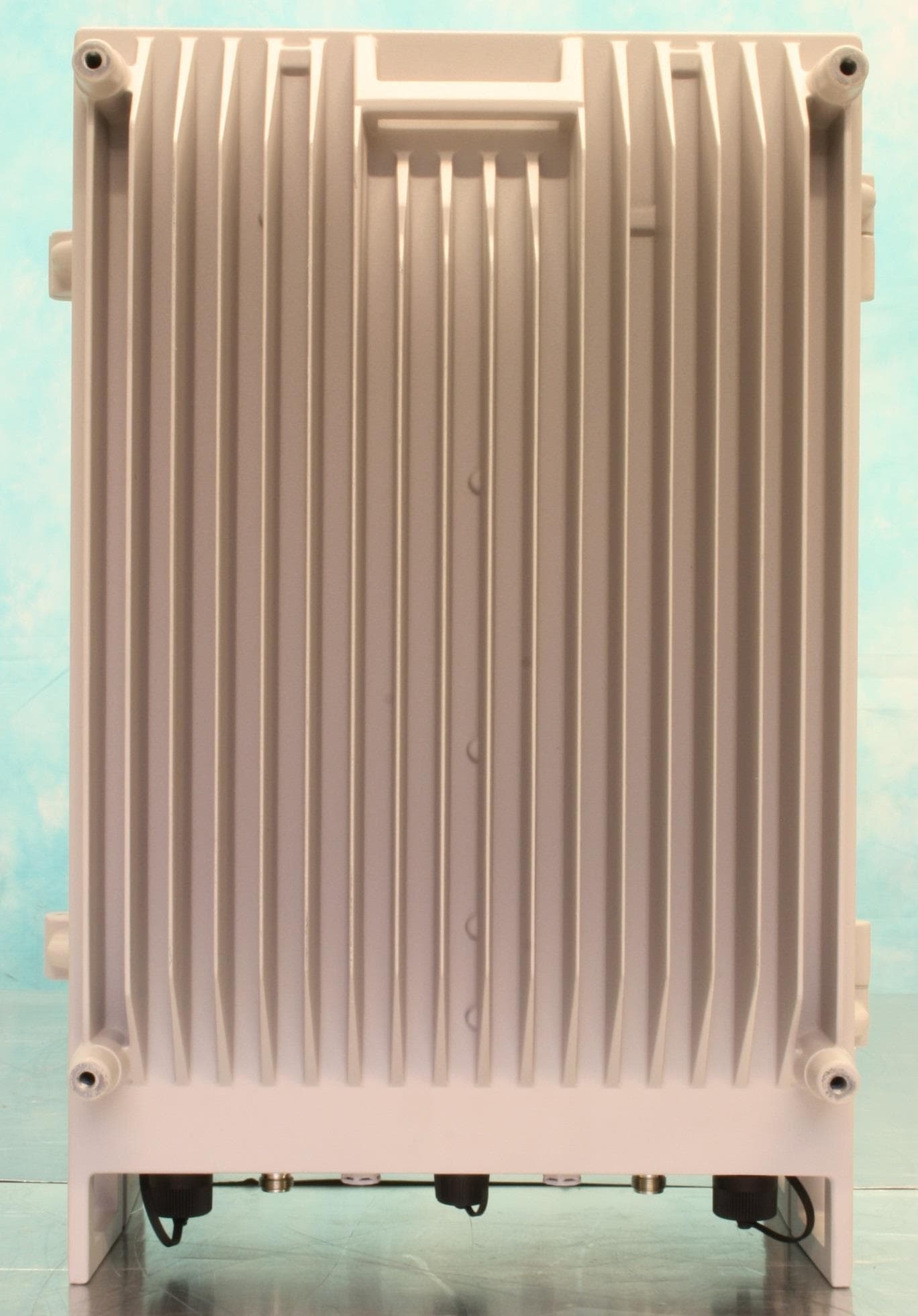
NEODSBR3709S
May 05, 2015D-SBR 3709S 900 MHz Booster
Equipment Class
B2I - Part 20 Industrial Booster (CMRS)