NEO60-1376SERIESSignal Booster type 60-137705
PBE Europe Ltd. trading as Axell Wireless
Click to zoom
Application Details
- Equipment Class
- TNB - Licensed Non-Broadcast Station Transmitter
- Date of Grant
- Mar 20, 2006
- Application Purpose
- Original Equipment
- Date of Application
- Mar 20, 2006
- Equipment Note
- Signal Booster type 60-137705
- Frequency Range
- 417.00000000 - 420.00000000
- Country
- United Kingdom
Documents & Files
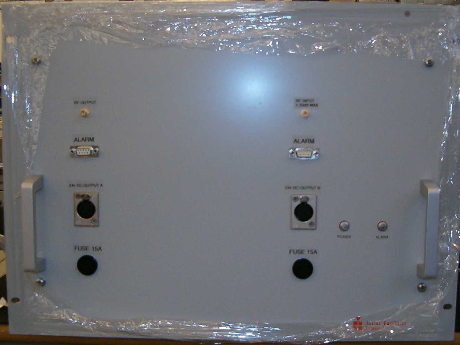
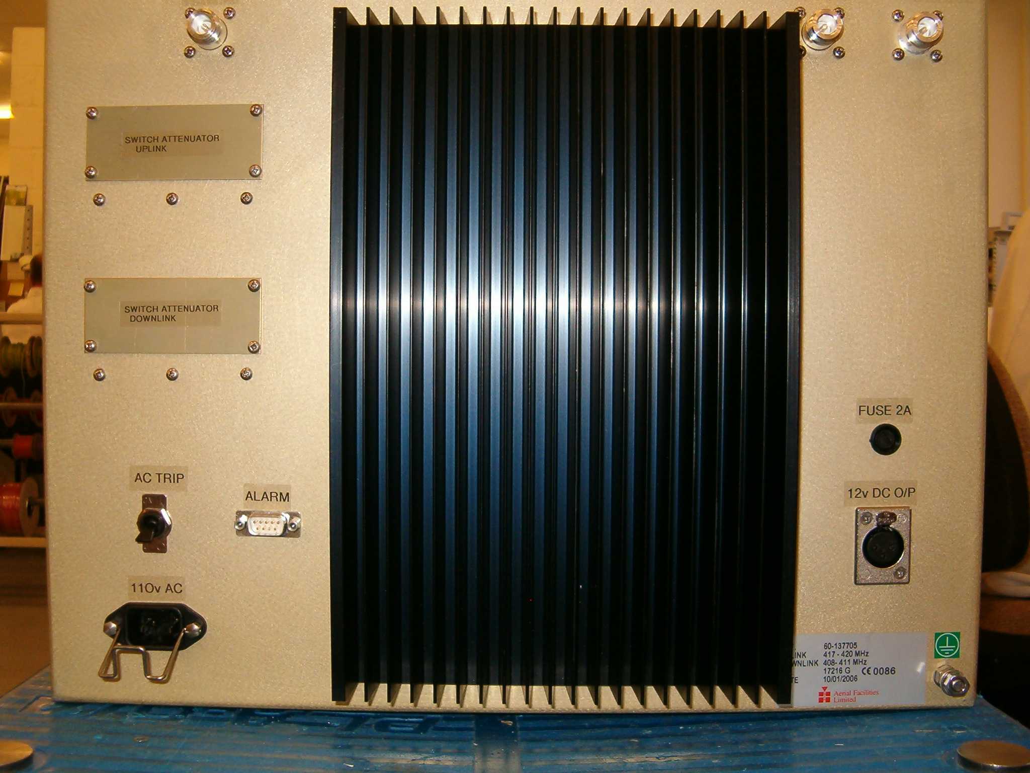
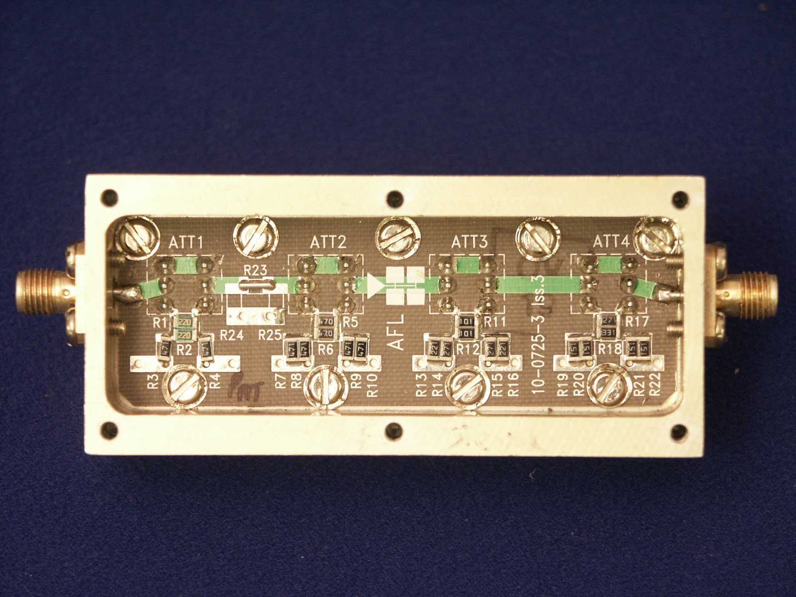
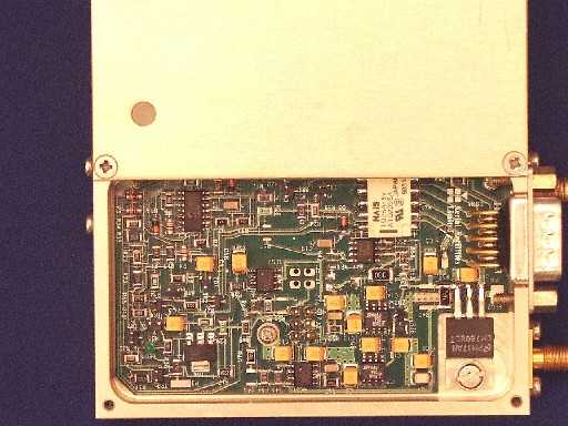
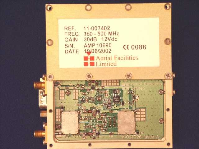
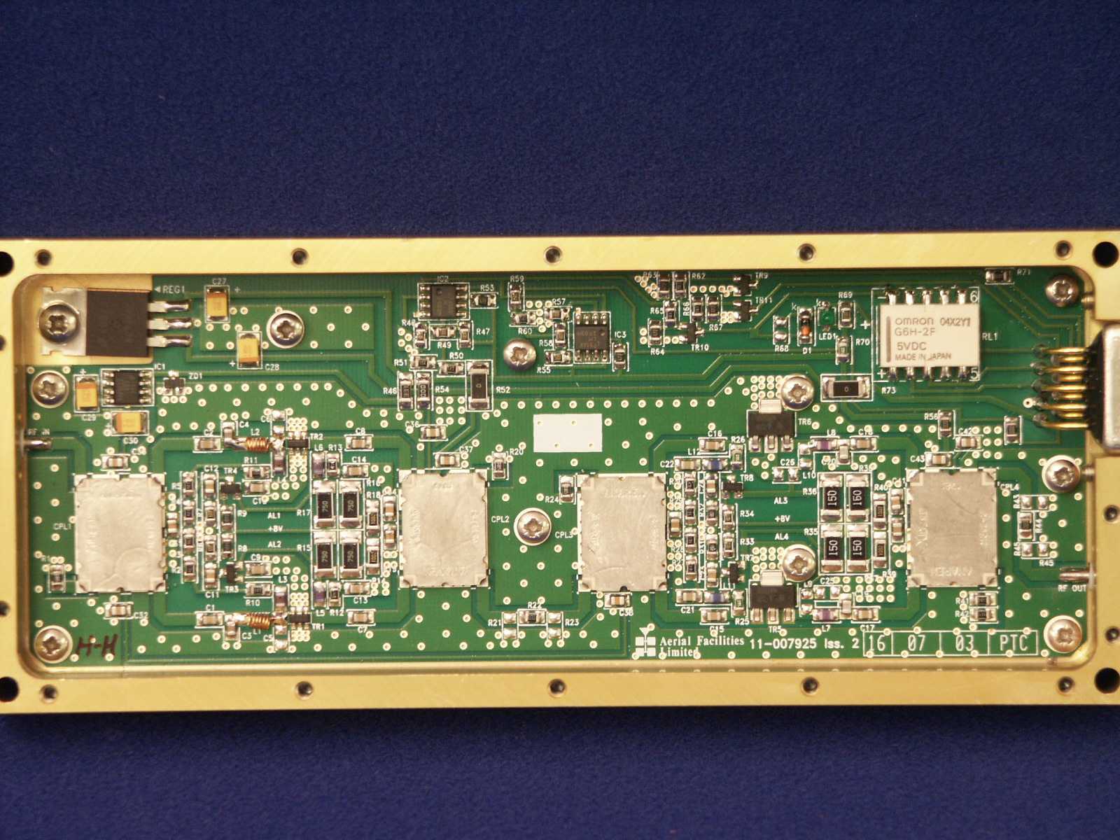
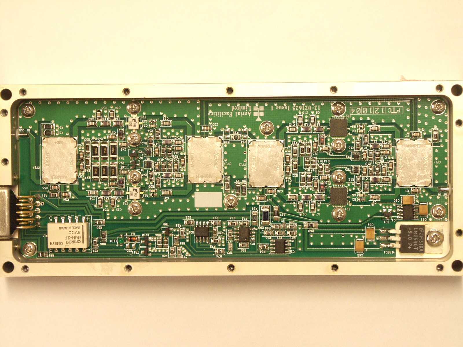
Document Text
Text extracted from the exhibit documents filed with the FCC. Open a document above to read the original.
Block Diagram
TXBTS NEO20-0040Series RXBTS NEO60-1376SERIES Buildin g NEO20-0041Series NEO20-0040Series NEO20-0041Series FIBRELINKFIBRELINK
ID Label/Location Info
BY DAT E DESCRIPT ION No THI RD ANGLE PROJECTI ON 1 2 34 5678 9 A BCDE F 1 234 5678 9 A BCD E F Fax : 01494 777002 Tel : 01494 777000 Aerial Facilities Limited THIS IS A PROPRIETARY DESIGN OF AERIAL FACILITIES LTD.RE P RODUCT ION OR US E OF T HIS DE S IGN B Y OT HE RS ISPERMISSIBLE ONLY IF EXPRESSLY AUTHORISED IN WRITINGBY AERIAL FACILITIES LTD. NO DECIMAL PLACE ± 1mmONE DECIMAL PLACE ± 0.3mmT WO DECIMAL PLACES ± 0.1mm ALL DIMENSIONS ARE IN mm UNLESS OTHERWISE STATED CHKD DRAWN APPDDAT E T OLERANCES SCALE England CUST OMER DRAWING.No TITLE ISSUE 3A FCC IDENT. LABEL POSITION RACK MOUNTED UNIT 80-312190 1A 1:5 DBS 30/9/03 PRODUCTION ISSUE 30/ 9/ 02 DBS Li m i t ed Aerial Facilities POWERALARM FCC IDENT. LABEL
Operational Description
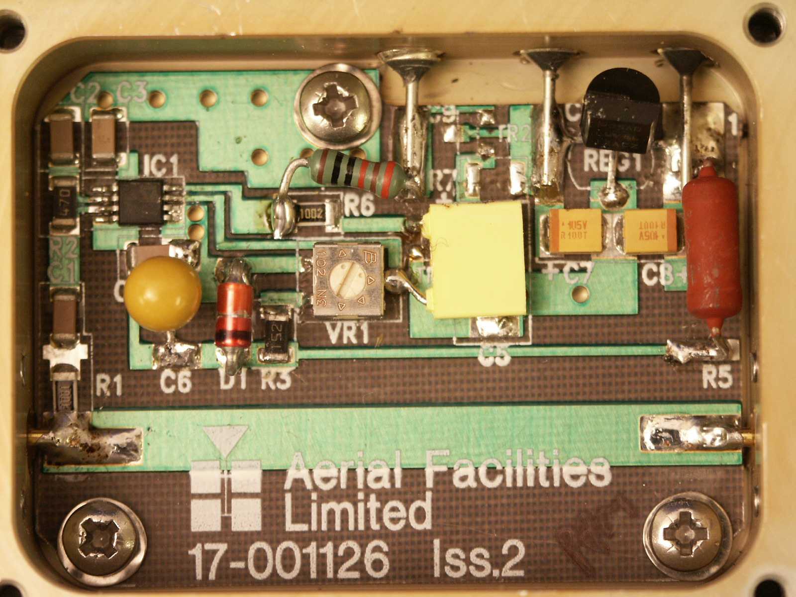
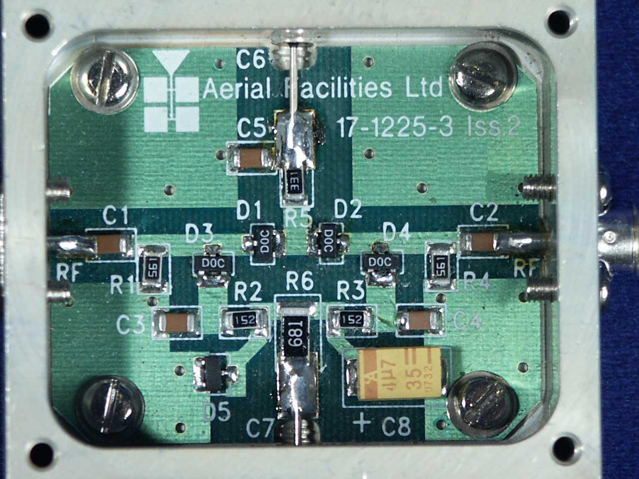
0.25Watt 0- -30dB Switched Attenuator (10-000701) General Application In many practical applications for Cell Enhancers etc., the gain in each path is found to be excessive. Therefore, provision is made within the unit for the setting of attenuation in each path, to reduce the gain. Switched Attenuators The AFL switched attenuators are available in two different types; 0 – 30dB in 2 dB steps (as in this case), or 0 – 15dB in 1 dB steps. The attenuation is simply set using the four miniature toggle switches on the top of each unit. Each switch is clearly marked with the attenuation it provides, and the total attenuation in line is the sum of the values switched in. They are designed to maintain an accurate 50Ω impedance over their operating frequency at both input and output. Wide Dynamic Range AGC (17-001105, Det. & 17-001201, Atten.) Description The equipment is fitted with a wide dynamic range Automatic Gain Control (AGC) system. This is generally fitted in the Uplink path (not usually needed in the downlink path, as the signal here is at an almost constant level), to avoid overloading the amplifiers (with the associated performance degradation) should a mobile be operated very close to the unit. The AFL wide dynamic range Automatic Gain Control system consists of two units, a detector/amplifier and an attenuator. The detector/amplifier unit is inserted in the RF path on the output of the power amplifier, and the attenuator is situated in the RF path between the 1st and 2nd stages of amplification. Normally the attenuator is at minimum attenuation. The detector/amplifier unit monitors the RF level being delivered by the power amplifier, and when a certain threshold is reached it begins to increase the value of the attenuator to limit the RF output to the (factory set) threshold. Therefore overloading of the power amplifier is avoided. The factory set threshold is 1dB below the Enhancer 1dB compression point. Some adjustment of this AGC threshold level is possible, a 10dB range is mostly achieved. It is not recommended under any circumstances to adjust the AGC threshold to a level greater than the 1dB compression point as system degradation will occur. The detector comprises of a 50Ω transmission line with a resistive tap which samples a small portion of the mainline power. The sampled signal is amplified and fed to a conventional half wave diode rectifier, the output of which is a DC voltage proportional to the RF input signal. This DC voltage is passed via an inverting DC amplifier with integrating characteristics, to the output, which drives the attenuation control line of the corresponding AGC attenuator. This unit is fitted at some earlier point in the RF circuit. The unit contains a 12V DC regulator in the detector module, which supplies stabilised voltage to the DC amplifier and via an external cableform to the AGC attenuator. For small signals, below AGC onset, the output control line will be close to 12V and the AGC attenuator will have minimum attenuation. As the signal level increases the control line voltage will fall, increasing the attenuator value and keeping the system output level at a constant value. The AGC onset level is adjusted by the choice of sampler resistor R1 and by the setting of potentiometer VR1, (factory set @ time of system test) do not adjust unless able to monitor subsequent RF levels. The attenuator comprises a 50Ω P.I.N diode, voltage-variable attenuator with a range of 3 to 30dB. The attenuation is controlled by a DC voltage which is derived from the associated AGC detector unit. Technical Specification PARAMETER SPECIFICATION Frequency Range: up to 1000MHz Attenuation Range: 3 to 30dB Attenuation Steps: continuously variable VSWR: better than 1.2:1 RF Connectors: SMA female attenuator: 1W Power Handling: detector/amp: >30W (or as required) operation: -10°C to +60°C Temperature Range: storage: -20°C to +70°C attenuator (pcb) 50 x 42 x 21mm Size: Detector (pcb) 54 x 42 x 21mm attenuator: 90grams Weight: detector/amp: 100grams Automatic Gain Control (17-001117, Det. & 17-001201, Atten.) Description The equipment is fitted with an Automatic Gain Control (AGC) system. This is generally fitted in the Uplink path (not usually needed in the downlink path, as the signal here is at an almost constant level), to avoid overloading the amplifiers (with the associated performance degradation) should a mobile be operated very close to the unit. Normally the attenuator is at minimum attenuation. The detector/amplifier unit monitors the RF level being delivered by the power amplifier, and when a certain threshold is reached it begins to increase the value of the attenuator to limit the RF output to the (factory set) threshold. Therefore overloading of the power amplifier is avoided. The factory set threshold is 1dB below the Enhancer 1dB compression point. Some adjustment of this AGC threshold level is possible, a 10dB range is mostly achieved. It is not recommended under any circumstances to adjust the AGC threshold to a level greater than the 1dB compression point as system degradation will occur. The detector comprises of a 50Ω transmission line with a resistive tap which samples a small portion of the mainline power. The sampled signal is amplified and fed to a conventional half wave diode rectifier, the output of which is a DC voltage proportional to the RF input signal. This DC voltage is passed via an inverting DC amplifier with integrating characteristics, to the output, which drives the attenuation control line of the corresponding AGC attenuator. This unit is fitted at some earlier point in the RF circuit. Note that this version of AGC system runs from a 12V DC supply and the circuit diagram shown in 5.7.4 is for the standard 24V version. The 12V circuit diagram is currently unavailable. For small signals, below AGC onset, the output control line will be close to 12V and the AGC attenuator will have minimum attenuation. As the signal level increases the co…
Text truncated - open the document above for the full version.
Test Report
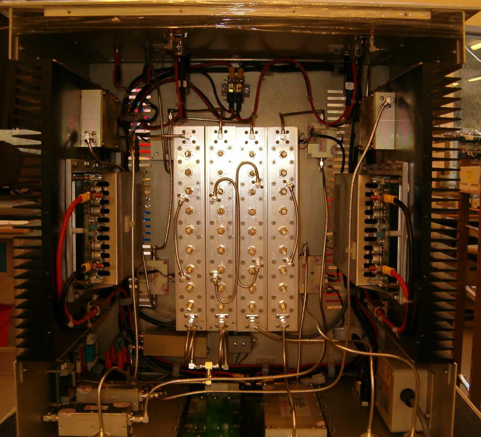
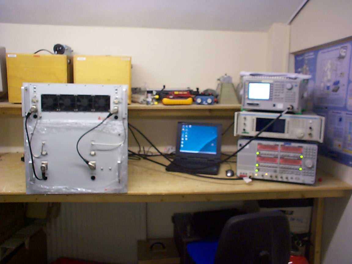
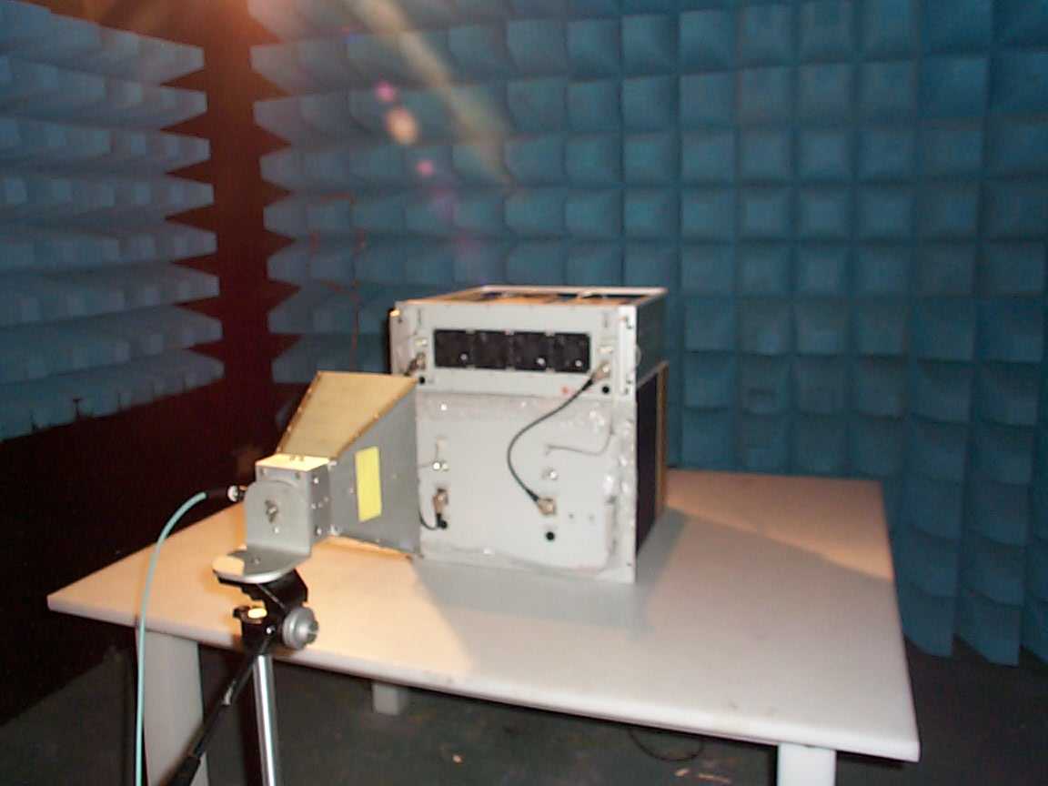
TRL COMPLIANCE LTD L ONG GREEN FORTHAMPTON GLOUCESTER GL19 4QH UNITED KINGDOM T ELEPHONE +44 (0)1684 833818 FAX +44 (0)1684 833858 E- MAIL [email protected] www.trlcompliance.com TEST REPORT NO: RU1220/6818 COPY NO: 2 ISSUE NO: 1 FCC ID: NEO60-1376SERIES REPORT ON THE CERTIFICATION TESTING OF A AERIAL FACILITIES LIMITED 60-137705 & 80-245102 WITH RESPECT TO THE FCC RULES CFR 47, PART 90 Subpart I PRIVATE LAND MOBILE REPEATER. TEST DATE: 11 th – 17 th January 2006 TESTED BY: D WINSTANLEY APPROVED BY: P GREEN PRODUCT MANAGER EMC DATE: 20 th March 2006 Distribution: Copy Nos: 1. Aerial Facilities Limited 2. TCB: TRL Compliance Limited 3. TRL Compliance Ltd THIS DOCUMENT MAY BE REPRODUCED ONLY IN ITS ENTIRETY AND WITHOUT CHANGE . RU1220/6818 Page 2 of 50 CONTENTS PAGE CERTIFICATE OF CONFORMITY & COMPLIANCE 3 APPLICANT’S SUMMARY 4 EQUIPMENT TEST CONDITIONS 5 TESTS REQUIRED 5 TEST RESULTS 6-39 ANNEX PHOTOGRAPHS A PHOTOGRAPH No. 1: Test setup PHOTOGRAPH No. 2: Test setup APPLICANT’S SUBMISSION OF DOCUMENTATION LIST B EQUIPMENT CALIBRATION C MEASUREMENT UNCERTAINTY D SYSTEM DIAGRAM E Notes: 1. Component failure during test YES NO [ ] [X] 2. If Yes, details of failure: 3. The facilities used for the testing of the product contain in this report are FCC Listed. RU1220/6818 Page 3 of 50 CERTIFICATE OF CONFORMITY & COMPLIANCE FCC IDENTITY: NEO60-1376SERIES PURPOSE OF TEST: Certification TEST SPECIFICATION: FCC RULES CFR 47, Part 90 Subpart I TEST RESULT: Compliant to Specification EQUIPMENT UNDER TEST: 60-137705 & 80-245102 EQUIPMENT TYPE: Private Land Mobile Repeater MAXIMIUM GAIN Uplink 61.91dB Downlink 60.92dB MAXIMUM INPUT Uplink -62.3 dBm Downlink -21.3 dBm MAXIMUM OUTPUT Uplink -0.39 dBm (input from fibre optic system) Downlink 39.62 dBm (radiating cable system) ANTENNA TYPE: Not applicable CHANNEL SPACING: Uplink, Determined by input signal channelisation Downlink, Determined by input signal channelisation NUMBER OF CHANNELS: Uplink, Determined by input signal channelisation Downlink, Determined by input signal channelisation FREQUENCY GENERATION: N/A MODULATION TYPE: F3E POWER SOURCE(s): +110 Vac TEST DATE(s): 11 th – 17 th January 2006 ORDER No(s): 34696 APPLICANT: Aerial Facilities Limited ADDRESS: Aerial House Asheridge Road Chesham Buckinghamshire HP5 1TU United Kingdom TESTED BY: D WINSTANLEY APPROVED BY: P GREEN PRODUCT MANAGER EMC RU1220/6818 Page 4 of 50 APPLICANT’S SUMMARY EQUIPMENT UNDER TEST (EUT): 60-137705 & 80-245102 EQUIPMENT TYPE: Private Land Mobile Repeater PURPOSE OF TEST: Certification TEST SPECIFICATION(s): FCC RULES CFR 47, Part 90 Subpart I TEST RESULT: COMPLIANT Yes No [X] [ ] APPLICANT’S CATEGORY: MANUFACTURER IMPORTER DISTRIBUTOR TEST HOUSE AGENT [X] [ ] [ ] [ ] [ ] APPLICANT’S ORDER No(s): 34696 APPLICANT’S CONTACT PERSON(s): Mr Peter Bradfield E-mail address: [email protected] APPLICANT: Aerial Facilities Limited ADDRESS: Aerial House Asheridge Road Chesham Buckinghamshire HP5 1TU United Kingdom TEL: +44 (0)1494 777000 FAX: +44 (0)1494 778456 MANUFACTURER: Aerial Facilities Limited EUT(s) COUNTRY OF ORIGIN: United Kingdom TEST LABORATORY: TRL Compliance Ltd. UKAS ACCREDITATION No: 0728 TEST DATE(s) 11 th – 19 th January 2006 TEST REPORT No: RU1220/6818 RU1220/6818 Page 5 of 50 EQUIPMENT TEST / EXAMINATIONS REQUIRED 1. TEST/EXAMINATION RULE PART APPLICABILITY RESULT RF Power Output 90.205 Yes Complies Audio Frequency Response TIA EIA-603.3.2.6 N/A N/A Audio Low-Pass Filter Response TIA EIA-603.3.2.6 N/A N/A Modulation Limiting TIA EIA-603.3.2.6 N/A N/A Occupied Bandwidth 90.210 Yes Complies Spurious Emissions at Antenna Terminals 90.210 Yes Complies Field Strength of Spurious Emissions 90.210 Yes Complies Frequency Stability 90.213 N/A(note 1) N/A Transient behaviour 90.214 N/A(note 2) N/A Notes: 1 The EUT does not contain modulation circuitry, therefore the test was not performed. 2 The EUT is not a keyed carrier system, therefore the test was not performed. Uplink Class A [ ] Class B [X] 2. Product class: Downlink Class A [ ] Class B [X] 3. Product Use: Private Land Mobile Repeater 4. Emission Designator: F3E 5. Temperatures: Ambient (Tnom) 21 o C 6. Supply Voltages: Vnom +110 Vac Note: Vnom voltages are as stated above unless otherwise shown on the test report page Single channel [ ] Two channel [ ] 7. Equipment Category: Multi-channel [X] 8. Channel spacing: Narrowband [ ] Wideband [X] 9. Test Location TRL Compliance Limited Up Holland [X] Long Green [ ] 10. Modifications made during test program No modifications were performed. System description: The 60-137705 and 80-245102 make up a bidirectional amplifier consisting of an uplink and a downlink. The uplink operates in the frequency band 417 MHz – 420MHz. The uplink input is determined by input signal channelisation and the output of the amplifier if fed into a fibre optic system FCC IDs NE020-0040Series and NE020-0041Series. The downlink operates in the frequency band 408.0 – 411.0 MHz. The downlink output of the amplifier is fed into a radiating cable system. The 60-137705 and 80-245102 are incorporated into a system as shown in Annex E. RU1220/6818 Page 6 of 50 COMPLIANCE TESTS AMPLIFIER GAIN – CONDUCTED – PART 2.1046 – UPLINK Ambient temperature = 22 o C Radio Laboratory Relative humidity = 53% Supply voltage = +110 Vac Channel number = See test results Frequency MHz Signal Generator input level dBm Cable & Attenuator loss dB Level at Spectrum Analyser dBm Gain dB Output Power dBm Gain after 10dB input level increase dBm 417.0 -61.30 10.15 -10.77 60.68 -0.62 50.91 418.5 -62.30 10.15 -10.54 61.91 -0.39 51.92 420.0 -61.30 10.15 -10.54 60.91 -0.39 50.92 Notes: 1. The level of the signal generator takes into consideration the loss from the cable. 2. The signal generator input was increased by 10dBs and the level of the output signal remeasured TYPE OF EQUIPMENT MAKER/ SUPPLIER MODEL No SERIAL No TRL No ACTUAL EQUIPMENT USED SPECTRUM ANALYSER ANRITSU MS2665C MT26089 479 X ATTENUATOR BIRD 8308-100 N/A 11…
Text truncated - open the document above for the full version.
Contact Information
Applicant
Michael Adam Godsey(VP of Design Engineering)
Technical Contact
Aerial Facilities LtdPeter Bradfield
[email protected]+44 1494 777020
Aerial House · Chesham, Bucks · United Kingdom
Test Firm
TRL Compliance LtdJohn Charters
Technical Specifications
| # | Rule Parts | Frequency Range | Power Output | Emission | Tolerance |
|---|---|---|---|---|---|
| 2 | 9 | 417 MHz - 420 MHz | 100.00 µW | F3E | Amp |
Other Applications from PBE Europe Ltd. trading as Axell Wireless

NEO61-105SERIES
Nov 27, 2022BSF3604
Equipment Class
B9B - Part 90 Class B Industrial Booster (non-SMR)
NEOA218DSERIES
Jul 14, 2022MBF-37D7-3708
Equipment Class
B2I - Part 20 Industrial Booster (CMRS)
NEO36IDRU420
May 06, 2020Class B Booster
Equipment Class
B9B - Part 90 Class B Industrial Booster (non-SMR)
NEODMBR37073708PS
Jan 04, 2016Class B Booster
Equipment Class
B9B - Part 90 Class B Industrial Booster (non-SMR)
NEODMBA30073008PS
Aug 30, 2015Class A Booster
Equipment Class
B9A - Part 90 Class A Industrial Booster (non-SMR)