NEOMBF4005SERIESMBF4005 Quad Band Optical Repeater
PBE Europe Ltd. trading as Axell Wireless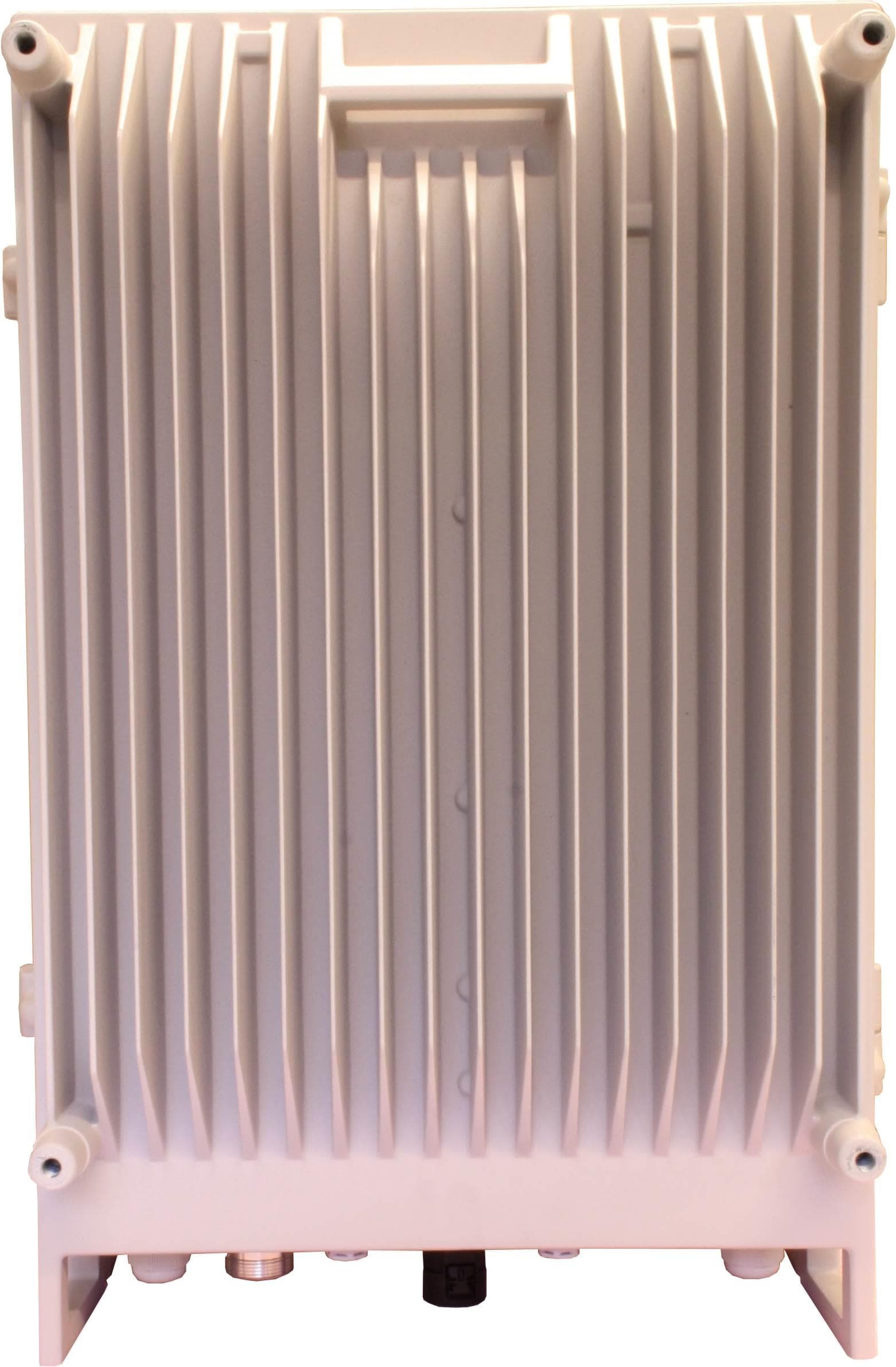
Click to zoom
Application Details
- Equipment Class
- B2I - Part 20 Industrial Booster (CMRS)
- Date of Grant
- Nov 20, 2014
- Application Purpose
- Original Equipment
- Date of Application
- Nov 04, 2014
- Equipment Note
- MBF4005 Quad Band Optical Repeater
- Frequency Range
- 1710.00000000 - 1755.00000000
- Country
- United Kingdom
Documents & Files
Document Text
Text extracted from the exhibit documents filed with the FCC. Open a document above to read the original.
Users Manual
AXELL MBF-40 AMERICAS REPEATERS PRODUCT DESCRIPTION AND USER’S MANUAL Axell MBF-40 Multi Band Repeater-Americas PRODUCT DESCRIPTION AND USER’S MANUAL Doc No. 00071UM Rev. 3.2 Single/Dual-Band Repeater Tri/Quad-Band Repeater Quad-Band with Fan Hood Repeater AXELL MBF-40 AMERICAS REPEATERS PRODUCT DESCRIPTION AND USER’S MANUAL II Doc. No. 00071UM Rev. 3.2 © Axell Wireless Ltd THIS DOCUMENT IS VALID FOR THE FOLLOWING MBF-40 MODELS: MBF-40 US Repeaters Dual Band MBF-3708-3719; MBF-3707-3917; MBF-3707-3719; MBF-3707-4317; MBF-4317-3919; MBF-4317-4319; Tri -Band MBF-3708-3917-3719; MBF-3707-3708-3917; MBF-3707-3708-3719; Quad-Band MBF-3707-3708-3917-3719; MIMO MBF-3917-3917M-3719 MBF-40 Canada Repeaters Single Band MBF-4307-AO; MBF-3707S-AO; Dual Band MBF-3708S-3709S-M; MBF-4317-4326-M; Quad-Band MBF-4308-4317-4319-4326-M-F MIMO MBF-4307-4307-M-AO AXELL MBF-40 AMERICAS REPEATERS PRODUCT DESCRIPTION AND USER’S MANUAL © Axell Wireless Ltd Doc. No. 00071UM Rev. 3.2 III Copyright © 2014 Axell Wireless Ltd All rights reserved. No part of this document may be copied, distributed, transmitted, transcribed, stored in a retrieval system, or translated into any human or computer language without the prior written permission of Axell Wireless Ltd. The manufacturer has made every effort to ensure that the instructions contained in this document are adequate and free of errors and omissions. The manufacturer will, if necessary, explain issues which may not be covered by this document. The manufacturer's liability for any errors in the document is limited to the correction of errors and the aforementioned advisory services. This document has been prepared to be used by professional and properly trained personnel, and the customer assumes full responsibility when using them. The manufacturer welcomes customer comments as part of the process of continual development and improvement of the documentation in the best way possible from the user's viewpoint. Please submit your comments to the nearest Axell Wireless sales representative. Contact Information Headquarters Axell Wireless Aerial House Asheridge Road Chesham Buckinghamshire HP5 2QD United Kingdom Tel: +44 1494 777000 Fax: +44 1494 777002 Commercial inquiries [email protected] Web site www.axellwireless.com Support issues [email protected] Technical Support Line, English speaking +44 1494 777 747 Contact information for Axell Wireless offices in other countries can be found on our web site, www.axellwireless.com AXELL MBF-40 AMERICAS REPEATERS PRODUCT DESCRIPTION AND USER’S MANUAL IV Doc. No. 00071UM Rev. 3.2 © Axell Wireless Ltd About This Manual This Product Manual provides the following information: • Description of the MBF-40 Americas Repeaters • Procedures for setup, configuration and checking the proper operation of the MBF-40 • Maintenance and troubleshooting procedures Intended Audience This Product Manual is intended for experienced technicians and engineers. It is assumed that the customers installing, operating, and maintaining Axell Wireless Remotes are familiar with the basic functionality of Remote repeaters. Notice Confidential - Authorized Customer Use This document may be used in its complete form only and is solely for the use of Axell Wireless employees and authorized Axell Wireless channels or customers. The material herein is proprietary to Axell Wireless. Any unauthorized reproduction, use or disclosure of any part thereof is strictly prohibited. All trademarks and registered trademarks are the property of their respective owners. Disclaimer of Liability Contents herein are current as of the date of publication. Axell Wireless reserves the right to change the contents without prior notice. The information furnished by Axell Wireless in this document is believed to be accurate and reliable. However, Axell Wireless assumes no responsibility for its use. In no event shall Axell Wireless be liable for any damage resulting from loss of data, loss of use, or loss of profits and Axell Wireless further disclaims any and all liability for indirect, incidental, special, consequential or other similes damages. This disclaimer of liability applies to all products, publications and services during and after the warranty period. Guarantees • All antennas must be installed with lightning protection. Damage to power modules, as a result of lightning are not covered by the warranty. • Antennas must be connected before switching on AC or DC power. Switching power on prior to the connection of antenna cables is regarded as faulty installation procedure and therefore not covered by the Axell Wireless warranty. Exclusive Remedies The remedies provided herein are the Buyer’s sole and exclusive remedies. Axell Wireless shall not be viable for any direct, incidental, or consequential damages, whether based on contract, tort, or any legal theory. AXELL MBF-40 AMERICAS REPEATERS PRODUCT DESCRIPTION AND USER’S MANUAL © Axell Wireless Ltd Doc. No. 00071UM Rev. 3.2 V Compliance with FCC FCC Part 20 Warning Statement WARNING: This is NOT a CONSUMER device. It is designed for installation by FCC LICENCEES and QUALIFIED INSTALLERS. You must have an FCC LICENCE or express consent of an FCC Licensee to operate this device. Unauthorized use may result in significant forfeiture penalties, including penalties in excess of $100,000 for each continuing violation. FCC Part 15 This device complies with part 15 of the FCC Rules. Operation is subject to the following two conditions: 1. This device may not cause harmful interference, and 2. This device must accept any interference received, including interference that may cause undesired operation. If not installed and used in accordance with the instructions, this equipment generates, uses and can radiate radio frequency energy. However, there is no guarantee that interference will not occur in a particular installation. If this equipment does cause harmful interference to RF reception, which can be determined b…
Text truncated - open the document above for the full version.
Users Manual
Product Specification Sheet ©Axell Wireless | www.axellwireless.com | [email protected] | Version: 3.5 | E & O.E. All specifications are subject to change without prior notice. 1 OMU II Optical Master Unit Key features: Supports Cellular 2G, 3G, 4G services up to 2700MHz & public safety services FM/VHF/UHF/LMR on the same enclosure Single enclosure to support high power (MBF-40) and low power (MBF-20) remote units MIMO support Web based remote management via wireless modem Flexible configuration to support up to 8 sectors via single chassis Simple integration to AEM or any other 3rd party NOC via SNMP traps The OMU II is used to convert signals from RF to light when fibre-fed repeaters are used at the remote end of the optical link. The OMU II is a headend system that can be connected directly to a base station or off-air device such as a digital repeater or bi-directional amplifier. For larger venues with multiple services and multiple bands, a Point Of Interface (POI) unit may be required to condition Uplink and Downlink RF signals between the BTS/Off-air Repeater and the OMU. In the downlink direction, the OMU picks up the signal from the BTS, converts it into an optical signal and transfers it over a fibre optical cable to the repeater. In the uplink direction, the OMU receives the signal from the remote repeater via the fibre optical cable, converts it to a RF signal and sends it back to the base station. Architecture Each OMU II has a dedicated control card, alarm and battery backup card, rack communication board (RCB), optional modem card and 2 AC/DC power supplies on the back of the chassis. It has 12 slots in the front to support the Opto Module cards and Signal Conditioning Card- Optical Splitter Module (OSM). The OSM cards include a 1:4 optical splitter hence it can support up to 4 MBF-20 units from a single OSM. The OMU II can support up to 8 of our standard high powered MBF-40 or 24 low powered MBF-20 remotes. For the maximum number on MBF-20 remote units, 6 Opto Modules and 6 OSM are used which may be configured according to the number of sectors used in the project – up to 6 sectors in this configuration. If only MBF-40 units are required, up to 8 Opto Module cards are used (no OSM cards) which may be configured according to the number of sectors used in the project – up to 8 sectors in this configuration. You can mix and match between the MBF-40 and MBF 20 remote units. Please refer to the 2nd page for all the available options. Automatic Optical Gain Setting The fibre optic system Axell Wireless has designed puts a clear focus on user friendliness and ease of installation and commissioning. Through an automatic optical gain setting, the commissioning is easily performed, thus reducing the time it takes to put the equipment in service. This also means that the training is significantly simplified and the need for installation effort is decreased. Remote Supervision Only one modem is needed to communicate with an OMU II and its fibre fed repeaters. The modem types available are GSM, UMTS, CDMA 1x, PSTN, and TCP/IP. The modem is found inside the OMU II and communication with the fibre- fed remote units is transparently handled via the fibre that connects them. The system can be monitored and controlled via the Axell Wireless’ network management software tool called AEM. AEM communicates with each fibre remote unit via the OMU over the same single mode fibre strand that carries the RF signals. Both data communications and the RF signals are managed over the same fibre link which results in a very reliable supervision of the radio link. The OMU Mark II supports: public safety services (VHF, UHF, TETRA, SMR 700/800/900), cellular bands for EMEA and APAC (800 / 900 / 1800 / 2100 / 2600) and LTE700, 850, PCS and AWS for Americas and is always used in combination with one or several fibre fed repeaters. ©Axell Wireless | www.axellwireless.com | [email protected] | Version: 3.5| E & O.E. All specifications are subject to change without prior notice. 2 Technical specifications RF Parameters Frequency bands 68-500 / 380-2200 / 700-2700 MHz Gain flatness typical 2 dB (p-p) Nominal RF input power +10 dBm composite power Absolute maximum RF input power +23 dBm composite power Number of optical modules 1-24 (depends on low/high power configuration) MBF-40 (high power) MBF-20 (low power) The table to the left lists the various high (MBF-40) and low (MBF-20) power remote unit configurations and how it affects the total number of links supported. For example: if the OMU II supports two high power fibre remotes, then the available low power links = 20 8 0 7 4 6 8 5 12 4 16 3 16 2 20 1 20 0 24 Laser class Class 1 Optical module electrical specification Optical wavelength Downlink (± 10 nm) 1310 Optical wavelength Uplink (± 3 nm) 1510 or 1530 or 1550 or 1570 or 1590 Maximum optical input power +5 dBm Output power (Tx) max +7 dBm Automatic fibre optic loss compensation Yes Optical Splitter Module (OSM) electrical specification Optical splitter (OSM) input power +5 ± 1 dBm Insertion loss 7dBo Power requirements Power requirements 230/115 VAC, 50/60 Hz,-48 VDC Power consumption Typical 50 W (fully equipped) External electrical interfaces Local maintenance terminal Ethernet, USB, RS232 RF ports N-type Connector Female for 1-2 sectors. SMA connectors for 8 sectors Optical ports SC/APC AC/DC mains input AC: IEC Connector with main lead supplied according to the region. DC: flying leads for connection to terminal block External alarms Via Front panel Modem connector RJ45 for wireless modem , RJ11 for PSTN modem Modem antenna connector (Wireless modem) SMA Ethernet connector RJ45 Mechanical specifications Dimensions (W x H x D) 17.5 x 5.2 x 11.4 in (444 x 132.5 x 291 mm) 19” rack Weight 33 lbs (15 kg) (fully equipped) IP rating IP20 Environmental Operating temperature +41 to 113° F (+5 to +45°C) About Axell Wireless Axell Wireless is one of the top global providers of wireless c…
Text truncated - open the document above for the full version.
Block Diagram
ATMEL AT91RM9200 PROCESSOR CONTROLLER H481003 RS232 Ethernet USB EXTERNAL INTERFACE_1 J691001 RS485 & Digital IO ALARM I/O x8 REFERENCE GENERATOR R031002 PIC16F876 PROCESSOR PSU_1 115V J791001 PIC16F876 PROCESSOR 28V15V 6.45V 6.45V BackUp PSU_2 115V J791001 PIC16F876 PROCESSOR 28V15V 6.45V 6.45V BackUp RS485 Σ PIC GAIN ADJ UL1 PIC PWR MEAS UL1 PIC ALC LEVEL UL1 Σ PIC GAIN ADJ DL1 PIC PWR MEAS DL1 PIC ALC LEVEL DL1 PIC18F6520 PROCESSOR MCPA 12-900801 UL1 RSS I DL1 RSSI STEP ATT STEP ATT ANALOG AND DIGITAL IO RB 700 D371030 Σ PIC GAIN ADJ UL1 PIC PWR MEAS UL1 PIC ALC LEVEL UL1 Σ PIC GAIN ADJ DL1 PIC PWR MEAS DL1 PIC ALC LEVEL DL1 PIC18F6520 PROCESSOR MCPA 1510993139 UL1 RSS I DL1 RSSI STEP ATT STEP ATT ANALOG AND DIGITAL IO RB 850 D211034 Σ PIC GAIN ADJ UL1 PIC PWR MEAS UL1 PIC ALC LEVEL UL1 Σ PIC GAIN ADJ DL1 PIC PWR MEAS DL1 PIC ALC LEVEL DL1 PIC18F6520 PROCESSOR MCPA 12-000903 UL1 RSS I DL1 RSSI STEP ATT STEP ATT ANALOG AND DIGITAL IO RB 1700 RA00138 Σ PIC GAIN ADJ UL1 PIC PWR MEAS UL1 PIC ALC LEVEL UL1 Σ PIC GAIN ADJ DL1 PIC PWR MEAS DL1 PIC ALC LEVEL DL1 PIC18F6520 PROCESSOR MCPA 12-900501 UL1 RSS I DL1 RSSI STEP ATT STEP ATT ANALOG AND DIGITAL IO RB 1900 RA00139 698-718 MHz777-787 MHz 728-756 MHz817-849 MHz862-894 MHz 1710-1755 MHz 2110-2155 MHz 1850-1915 MHz 1930-1995 MHz MULTIPLEXER 1513001186 7/16 N type SERVER ANTENNA SC/APC 9/125 SM FIBRE 10 MHz 10 MHz REF Pilot Tx 1045 MHz FSK Modem Tx 26.9 MHz PIC LILOT ENABLE PIC UL FSK DATA PIC OPTO PWR SET LASER PWR MONITOR 1550 nm 1310 nm PIC DL OPTO PWR MONITOR FSK RX FSK Modem Rx 29.9 MHz PIC DL FSK DATA PIC PILOT RSSI OPTO IN /OUT SMA SMA SMASMA SMA SMA Receive Quadplexer 1513001217 Transmit Quadplexer 1513001216 OPTO M0DULE J1311001 SMASMA SMA SMASMASMASMASMA MBF4005 Repeater – Block Diagram SMA SMA SMA SMA SMA SMA SMA SMA SMA SMA SMA SMA SMA SMA SMA SMA SMASMA SMA SMA
Cover Letter(s)
Axell Wireless UK Asheridge Road Chesham Bucks HP5 2QD 01 April 2014 Part 20 Industrial booster advisory letter For the attention of Brian Barton, Peter Bradfield As a TCB we are required to advise you of all of the criteria outlined in Part 20 relating to booster operations. The following pages contain the §20.21 CMRS signal booster guidance and requirements around licensing/expressed consent, labelling requirements and marketing rules. For Industrial boosters, please refer to sections (c) for operational requirements specifying licensing or expressed consent of the licensee whose frequencies are being retransmitted by the device on a regular basis. Section (f) provides the labelling requirements. Yours sincerely Peter Green EMC and Radio Specialist §20.21 Signal boosters. (a) Operation of Consumer Signal Boosters. A subscriber in good standing of a commercial mobile radio service system may operate a Consumer Signal Booster for personal use under the authorization held by the licensee providing service to the subscriber provided that the subscriber complies with paragraphs (a)(1) through (6). Failure to comply with all applicable rules in this section and all applicable technical rules for the frequency band(s) of operation voids the authority to operate the Consumer Signal Booster. (1) Prior to operation, the subscriber obtains the consent of the licensee providing service to the subscriber; (2) Prior to operation, the subscriber registers the Consumer Signal Booster with the licensee providing service to the subscriber; (3) The subscriber only operates the Consumer Signal Booster with approved antennas, cables, and/or coupling devices as specified by the manufacturer of the Consumer Signal Booster; (4) The subscriber operates the Consumer Signal Booster on frequencies used for the provision of subscriber-based services under parts 22 (Cellular), 24 (Broadband PCS), 27 (AWS-1, 700 MHz Lower A-E Blocks, and 700 MHz Upper C Block), and 90 (Specialized Mobile Radio) of this chapter. Operation on part 90 (Specialized Mobile Radio) frequencies is permitted upon the Commission's release of a public notice announcing the date Consumer Signal Boosters may be used in the band; (5) The Consumer Signal Booster complies with paragraphs (e), (f), (g), and (h) of this section and §2.907 of this chapter; and (6) The subscriber may not deactivate any features of the Consumer Signal Booster which are designed to prevent harmful interference to wireless networks. These features must be enabled and operating at all times the signal booster is in use. (b) De minimis operation of Consumer Signal Boosters. A third party's incidental use of a subscriber's Consumer Signal Booster operated under this paragraph is de minimis and shall be authorized under the authorization held by the licensee providing service to the third party. (c) Operation of Industrial Signal Boosters. An individual or non-individual, other than a representative of a foreign government, may operate an Industrial Signal Booster provided that the individual or non-individual: (1) Has an FCC license or obtains the express consent of the licensee(s) whose frequencies are being retransmitted by the device on a regular basis, and (2) Uses an Industrial Signal Booster which complies with paragraph (f) of this section. (d) Operation on a secondary, non-interference basis. Operation of signal boosters under this section is on a secondary, non-interference basis to primary services licensed for the frequency bands on which they transmit, and to primary services licensed for the adjacent frequency bands that might be affected by their transmissions. (1) The operation of signal boosters must not cause harmful interference to the communications of any primary licensed service. (2) Upon request of an FCC representative or a licensee experiencing harmful interference, a signal booster operator must: (i) Cooperate in determining the source of the interference, and (ii) If necessary, deactivate the signal booster immediately, or as soon as practicable, if immediate deactivation is not possible. (e) Consumer Signal Booster Network Protection Standard. (1) All Consumer Signal Boosters must incorporate features to prevent harmful interference to wireless networks including but not limited to those enumerated in this section. (2) Certification requirements. (i) A Consumer Signal Booster can only be certificated and operated if it complies with all applicable rules in this subpart and all applicable technical rules for the frequency band(s) of operation including, but not limited to: §22.355 of this chapter, Public Mobile Services, frequency tolerance; §22.913 of this chapter, Cellular Radiotelephone Service effective radiated power limits; §22.917 of this chapter, Cellular Radiotelephone Service, emission limitations for cellular equipment; §24.232 of this chapter, Broadband Personal Communications Service, power and antenna height limits; §24.238 of this chapter, Broadband Personal Communications Service, emission limitations for Broadband PCS equipment; §27.50 of this chapter, Miscellaneous Wireless Communications Services, power and antenna height limits; §27.53 of this chapter, Miscellaneous Wireless Communications Services, emission limits; §90.205 of this chapter, Private Land Mobile Radio Services, power and antenna height limits; §90.210 of this chapter, Private Land Mobile Radio Services, emission masks; and §90.247 of this chapter, Private Land Mobile Radio Services, mobile repeater stations. (ii) In case of any conflict between the rules set forth in this section and the rules set forth in parts 22, 24, 27, and 90 of title 47, chapter I of the Code of Federal Regulations, the rules in this section shall govern. (iii) The application for certification must satisfy the Commission that the Consumer Signal Boosters' features designed to prevent harmful interference and protect wireless networks cannot be easily defeated and must be enabled at all times…
Text truncated - open the document above for the full version.
External Photos
MBF 4005 external Page 1 of 5 MBF 4005 external Page 2 of 5 MBF 4005 external Page 3 of 5 MBF 4005 external Page 4 of 5 MBF 4005 external Page 5 of 5
ID Label/Location Info
MBF 4005 label positions Page 1 of 1
Internal Photos
1510993139 Page 1 of 2 1510993139 Page 2 of 2 12-900501 Page 1 of 2 12-900501 Page 2 of 2 12-900801 Page 1 of 2 12-900801 Page 2 of 2 151301186 Page 1 of 3 151301186 Page 2 of 3 151301186 Page 3 of 3 151301216 Page 1 of 2 151301216 Page 2 of 2 151301217 Page 1 of 2 151301217 Page 2 of 2 12-000903 Page 1 of 3 12-000903 Page 2 of 3 12-000903 Page 3 of 3
Internal Photos
J641030B Distribution Board D211034 Page 1 of 2 D211034 Page 2 of 2
Internal Photos
J1311001 FO module
Internal Photos
RA00139 Page 1 of 2 RA00139 Page 2 of 2 R031002B Reference Generator. RA00138 Page 1 of 2 RA00138 Page 2 of 2 MBF 4005 internal Page 1 of 3 MBF 4005 internal Page 2 of 3 MBF 4005 internal Page 3 of 3
RF Exposure Info
RADIO FREQUENCY RADIATION EXPOSURE FCC KDB 447498 D03 Radio frequency radiation exposure evaluation. Devices that operate under CFR47 Part 20 are subject to routine environmental evaluation for RF exposure prior to equipment authorization or use if they operate at frequencies of 1.5 GHz or below and their effective radiated power (ERP) is 1.5 watts or more for FCC requirements and 2.5 Watts or more for Industry Canada Requirements. Prediction of MPE limit at a given distance Equation from page 18 of OET Bulletin 65, Edition 97-01 where: S = power density R = distance to the centre of radiation of the antenna EIRP = EUT Maximum power LIMITS FCC LIMITS FOR MAXIMUM PERMISSIBLE EXPOSURE (MPE) (B) Limits for General Population/Uncontrolled Exposure Frequency Range (MHz) Electric Field (V/m rms) Magnetic Field (A/m rms) Power Density (W/m2) Averaging Time |E| 2 , |H| 2 or S (minutes) 0.3-1.34 614 1.63 (100)* 30 1.34-30 824/f 2.19/f (180/f2)* 30 30-300 27.5 0.073 0.2 30 300-1500 -- -- f/1500 30 1500-100,000 -- -- 1.0 30 f = frequency in MHz *Plane-wave equivalent power density 4 arranged-re 4 2 S EIRP R R EIRP S Uplink FCC Prediction Frequency (MHz) Conducted Output Power dBm Maximum Antenna Gain (dBi) Peak Output Power EIRP (dBm) Peak Output Power EIRP (mW) Power Density limit (S) (mW/cm 2 ) Distance (R) cm required to be less than (S) 700MHz (Lower) 698.000 -14.67 9 -5.67 0.2710 0.465 0.22 707.000 -14.72 9 -5.72 0.2679 0.471 0.22 716.000 -14.30 9 -5.30 0.2951 0.477 0.23 700MHz (Upper) 776.000 -15.83 9 -6.83 0.2075 0.517 0.18 781.500 -16.34 9 -7.34 0.1845 0.521 0.17 787.000 -16.32 9 -7.32 0.1854 0.525 0.17 850 MHz 817.000 -15.12 9 -6.12 0.2443 0.545 0.19 833.000 -14.40 9 -5.40 0.2884 0.555 0.21 849.000 -15.02 9 -6.02 0.2500 0.566 0.19 1800 MHz 1880.000 -14.00 9 -5.00 0.3162 1.000 0.16 1897.500 -13.92 9 -4.92 0.3221 1.000 0.17 1915.000 -13.93 9 -4.93 0.3214 1.000 0.16 1700 MHz 1710.000 -13.78 9 -4.78 0.3327 1.000 0.17 1732.500 -14.06 9 -5.06 0.3119 1.000 0.16 1755.000 -14.37 9 -5.37 0.2904 1.000 0.16 Downlink FCC Prediction Frequency (MHz) Conducted Output Power dBm Maximum Antenna Gain (dBi) Peak Output Power EIRP (dBm) Peak Output Power EIRP (mW) Power Density limit (S) (mW/cm 2 ) Distance (R) cm required to be less than (S) 700MHz 728.000 35.93 9 44.93 31117.163371 0.485 72 742.000 36.19 9 45.19 33036.954104 0.495 73 757.000 35.43 9 44.43 27733.201047 0.505 67 850 MHz 862.000 35.81 9 44.81 30269.134281 0.575 60 878.000 36.37 9 45.37 34434.993076 0.585 69 894.000 36.27 9 45.27 33651.156938 0.596 68 1900 MHz 1930.000 36.33 9 45.33 34119.291162 1.000 53 1962.500 37.10 9 46.10 40738.027780 1.000 57 1995.000 36.53 9 45.53 35727.283815 1.000 54 2100 MHz 2110.000 38.06 9 47.06 50815.944256 1.000 64 2132.500 38.57 9 47.57 57147.863667 1.000 68 2155.000 38.39 9 47.39 54827.696492 1.000 67
Test Report
A RADIO TEST REPORT FOR AXELL WIRELESS LIMITED ON MBF-7-8-17-19/GB DOCUMENT NO. TRA-020407-47-00-D TRaC Wireless Test Report : TRA-020407-47-01-D Applicant : Axell Wireless Limited Apparatus : MBF-7-8-17-19/GB Specification(s) : CFR47 Part 90, Part 22, Part 24, Part 27 Purpose of Test : Certification FCCID : NEOMBF4005SERIES Authorised by : : Radio Product Manager Issue Date : 20 th November 2014 Authorised Copy Number : PDF Total number of pages: 164 TRaC Global Test Report: TRA-020407-47-01-D Contents Section 1: Introduction 4 1.1 General 4 1.2 Tests Requested By 5 1.3 Manufacturer 5 1.4 Apparatus Assessed 5 1.5 Test Result Summary 6 1.6 Equipment Test Conditions 7 1.7 Standard References 8 1.8 Notes Relating To Assesment 9 1.9 Deviations from Test Standards 9 Section 2: Measurement Uncertainty 10 2.1 Measurement Uncertainty Values 10 Section 3: Modifications 12 3.1 Modifications Performed During Assessment 12 Appendix A: Uplink Formal Emission Test Results 13 A1 RF Gain and Output Power 14 A2 Amplifier Intermodulation Spurious Emissions 16 A3 Amplifier Modulated Channel Test 27 A4 Spurious Emissions at Antenna Terminals Less than 1MHz 37 A5 Spurious Emissions at Antenna Terminals Greater than 1 MHz 40 A6 Radiated Electric Field Emissions 62 A7 Passband Gain & Bandwidth 80 Appendix B: Downlink Formal Emission Test Results 82 B1 RF Gain and Output Power 83 B2 Amplifier Intermodulation Spurious Emissions 84 B3 Amplifier Modulated Channel Test 94 B4 Spurious Emissions at Antenna Terminals Less than 1MHz 104 B5 Spurious Emissions at Antenna Terminals Greater than 1MHz 117 B6 Radiated Electric Field Emissions 136 B7 Passband Gain & Bandwidth 153 Appendix C: Additional Test and Sample Details 155 Appendix D: Additional Information 161 Appendix E: Photographs and Figures 162 3 TRaC Global Test Report: TRA-020407-47-01-D Section 1: Introduction 1.1 General This report contains an assessment of an apparatus against Electromagnetic Compatibility Standards based upon tests carried out on samples submitted to the Laboratory. Test performed by: TRaC Global [ ] Unit E South Orbital Trading Park Hedon Road Hull, HU9 1NJ. United Kingdom. Telephone: +44 (0) 1482 801801 Fax: +44 (0) 1482 801806 TRaC Global [X] Unit 1 Pendle Place Skelmersdale West Lancashire, WN8 9PN United Kingdom Telephone: +44 (0) 1695 556666 Fax: +44 (0) 1695 577077 Email: [email protected] Web site: http://www.tracglobal.com Tests performed by: S Hodgkinson Report author: S Hodgkinson This report must not be reproduced except in full without prior written permission from TRaC Global. 4 TRaC Global Test Report: TRA-020407-47-01-D 1.2 Tests Requested By This testing in this report was requested by : Axell Wirelesss Limited Aerial House Asheridge Road Chesham Buckinghamshire HP5 1TU 1.3 Manufacturer Axell Wireless Limited Aerial House Asheridge Road Chesham Buckinghamshire HP5 1TU 1.4 Apparatus Assessed The following apparatus was assessed between and 16 th July and 12 th August 2014 Fibre Optic (F/O) Remote Unit The Multi-Band Fibre Optic system is composed of two building blocks: OMU (Optical Master unit) and MBF-40 series (Fibre Distributed Antenna System) Remote Unit. This is an indoor solution for single or multi operator use. Technical specifications Frequency Range Uplink Downlink CFR 47 Rule Part 700 MHz Lower band 698 - 716 MHz and Upper band 776 - 787 MHz Lower band 728 - 746 MHz and Upper band 746 - 757 MHz 27, Subpart A 850 MHz (cellular) 824 - 849 MHz 869 - 894 MHz 22, Subpart C SMR 800 (Sprint) 817 - 824MHz 862 - 869 MHz 90, Subpart S 1900 MHz (PCS) 1850 - 1910 MHz 1930 - 1990 MHz 24, Subpart E 1700 MHz (AW S) 1710 - 1755 MHz 2110 - 2155 MHz 27, Subpart A 5 TRaC Global Test Report: TRA-020407-47-01-D 1.5 Test Result Summary Full details of test results are contained within Appendix A. The following table summarises the results of the assessment. The statements relating to compliance with the standards below apply ONLY as qualified in the notes and deviations stated in sections 1.6 to 1.7 of this test report. Full details of test results are contained within Appendix A. The following table summarises the results of the assessment. Test Type FCC Part 2 CFR 47 Part 22 Subpart H CFR 47 Part 24 Subpart E CFR 47 Part 27 Subpart A CFR 47 Part 90 Subpart S Appendix in Report RF Power Output 2.1046 22.913(a) 24.232(a) 27.50 (a) 90.205(k) A1 & B1 Intermodulation Spurious Emissions 2.1051 22.917(a) 24.238(a) 27.53(c) & (g) 90.691(a)(1) & (2) A2 & B2 Occupied Bandwidth & Modulation 2.1049 *KDB 935210 N/A N/A N/A N/A A3 & B3 Spurious Emissions at Antenna Terminals Less than 1 MHz 2.1051 22.917(a) 24.238(a) 27.53(c) & (g) 90.691(a)(1) & (2) A4 & B4 Spurious Emissions at Antenna Terminals Greater than 1MHz 2.1051 22.917(a) 24.238(a) 27.53(c) & (g) 90.691(a)(1) & (2) A5 & B5 Field Strength of Spurious Emissions 2.1053 22.917(a) 24.238(a) 27.53(c),(f) & (g) 90.691(a)(1) & (2) A6 & B6 Passband Gain & 20dB bandwidth *KDB 935210 N/A N/A N/A N/A A7 & B7 Frequency Stability 2.1055 22.355 24.135 27.54 90.213 N/A(note 1) Transient behaviour 2.1055 N/A N/A N/A N/A N/A(note 2) Audio Frequency Response (a) TIA EIA- 603.3.2.6 N/A N/A N/A N/A N/A Modulation Limiting TIA EIA- 603.3.2.6 N/A N/A N/A N/A N/A Signal Booster Labelling Requirements 20.21(f)(1)(ii) N/A N/A N/A N/A N/A Notes: 1 The EUT does not contain modulation circuitry; therefore the test was not performed. 2 The EUT is not a keyed carrier system; therefore the test was not performed. Abbreviations used in the above table: CFR : Code of Federal Regulations ANSI : American National Standards Institution REFE : Radiated Electric Field Emissions PLCE : Power Line Conducted Emissions A Uplink Results Appendix B Downlink Results Appendix 6 TRaC Global Test Report: TRA-020407-47-01-D 1.6 Equipment Test Conditions Product class: Uplink Class A [ ] Class B [X] Downlink Class A [ ] Class B [X] Product Use: Private Land Mobile Repeater Emission Designator(s): Supply Voltages: Vnom +230Vac/110Vac…
Text truncated - open the document above for the full version.
Test Report
TRaC Global Test Report: TRA-020407-47-01-D A t t 5 d B ** A Ref- 6. 4 d Bm Offset 0.4 dB LVL 11 MHz/Center707 MHzSpan110 MHz * 3DB RBW 100 kHz VBW 300 kHz SWT 50 ms* 1 PK MAXH -100 -90 -80 -70 -60 -50 -40 -30 -20 -10 1 Marker 1 [T1 ] -13.87 dBm 716.519230769 MHz ndB [T1] 20.00 dB BW 27.852564103 MHz T1 Temp 1 [T 1 n dB ] -34.04 dBm 693.426282051 MHz T2 Temp 2 [T1 ndB] - 33 . 38 d B m 721.278846154 MHz Date: 1.AUG.2014 15:03:24 Att 5 dB** A Ref-6.4 dBm Off s et 0. 4 d B LVL * 3DB R B W 1 0 0…
Text truncated - open the document above for the full version.
Contact Information
Applicant
Michael Adam Godsey(VP of Design Engineering)
Test Firm
Element Materials Technology Warwick LtdStewart Barrowclough
Technical Specifications
| # | Rule Parts | Frequency Range | Power Output | Emission | Tolerance |
|---|---|---|---|---|---|
| 4 | 27 | 1.71 GHz - 1.75 GHz | 40.00 µW | G7W | Amp |
Other Applications from PBE Europe Ltd. trading as Axell Wireless

NEO61-105SERIES
Nov 27, 2022BSF3604
Equipment Class
B9B - Part 90 Class B Industrial Booster (non-SMR)
NEOA218DSERIES
Jul 14, 2022MBF-37D7-3708
Equipment Class
B2I - Part 20 Industrial Booster (CMRS)
NEO36IDRU420
May 06, 2020Class B Booster
Equipment Class
B9B - Part 90 Class B Industrial Booster (non-SMR)
NEODMBR37073708PS
Jan 04, 2016Class B Booster
Equipment Class
B9B - Part 90 Class B Industrial Booster (non-SMR)
NEODMBA30073008PS
Aug 30, 2015Class A Booster
Equipment Class
B9A - Part 90 Class A Industrial Booster (non-SMR)