NF28238-49Radio Control Model Car Lotus Exige
Hitari Limited
Click to zoom
Application Details
- Equipment Class
- DXX - Part 15 Low Power Communication Device Transmitter
- Date of Grant
- Jun 29, 2005
- Application Purpose
- Original Equipment
- Date of Application
- Jun 29, 2005
- Equipment Note
- Radio Control Model Car Lotus Exige
- Frequency Range
- 49.86000000 - 49.86000000
- Company
- Hitari Limited
- Country
- United Kingdom
Documents & Files
Document Text
Text extracted from the exhibit documents filed with the FCC. Open a document above to read the original.
Cover Letter(s)
Random House, 14 Hall Drive, Bramhope, Leeds LS16 9JE, UK Phone (44) 113 203 7332 Fax (44) 113 203 7340
External Photos
FCC ID: NF28238-49 ——————————————————————————————————————————————— Advanced Compliance Lab, 6 Randolph Way, Hillsborough, NJ 08844 Tel: (908) 927-9288 Fax: (908) 927- 0728 16 Front View FCC ID: NF28238-49 ——————————————————————————————————————————————— Advanced Compliance Lab, 6 Randolph Way, Hillsborough, NJ 08844 Tel: (908) 927-9288 Fax: (908) 927- 0728 17 Rear View
ID Label/Location Info
FCC ID: NF28238-49 ——————————————————————————————————————————————— Advanced Compliance Lab, 6 Randolph Way, Hillsborough, NJ 08844 Tel: (908) 927-9288 Fax: (908) 927-0728 8 2. PRODUCT LABELING Figure 2.1 FCC ID Label Figure 2.2 Location of Label on the Side of EUT FCC ID: NF28238-49 This device complies with part 15 of the FCC Rules. Operating is subject to the following two conditions: (1) This device may not cause harmful interference, and (2) this device must accept any interference received, including interference that may cause undesired operation. Figure 2.1 FCC ID Label (FCC Statement may show in User Manual only) FCC Label Figure 2.2 Location of Label on Back of the EUT
Internal Photos
FCC ID: NF28238-49 ——————————————————————————————————————————————— Advanced Compliance Lab, 6 Randolph Way, Hillsborough, NJ 08844 Tel: (908) 927-9288 Fax: (908) 927- 0728 18 Open View FCC ID: NF28238-49 ——————————————————————————————————————————————— Advanced Compliance Lab, 6 Randolph Way, Hillsborough, NJ 08844 Tel: (908) 927-9288 Fax: (908) 927- 0728 19 Component Side FCC ID: NF28238-49 ——————————————————————————————————————————————— Advanced Compliance Lab, 6 Randolph Way, Hillsborough, NJ 08844 Tel: (908) 927-9288 Fax: (908) 927- 0728 20 Foil Side
Operational Description
May 09, 2005 Remote Controller car set 8238-49TR Functional Description The EUT comprises a radio controller and a radio control car while the controller is used to control the car by means of transmitting a radio frequency signal in a simplex mode. The controller – The controller comprises a rf generation circuit and a modulation circuit. In the rf generation circuit, rf frequency carrier is generated continually by a crystal oscillating at 49.860 MHz when the power is switched on. However the rf signal will not further transmit forward to second stage for amplification and radiates via antenna matching network until there is presence of a modulating signal (the control signal). In the modulation circuit, modulating signal is generated by an encoder IC. By changing the values of the variable resistors on the controller, control signal in analogue level will be set at the different input pins of the IC, A to D converting process is carried out inside IC and a series of digital data bits will be generated. The level of data bits are high enough to switch on and off (ON/OFF keying) a control gate allowing the rf carrier to pass through to next stage for amplification and hence radiates to atmosphere via the antenna network. Three different algorithm for coding are available by selecting the ABC switch of the controller, which allows three different sets of control signals to be transmitted at same time and in the same frequency, and hence three controllers can control three cars at the same time without interfering each other. Antenna is a telescopic design. The controller is powered by a 9V dry battery. No supply ground or signal ground is available. The radio control car (receiver) – The receiver comprises a rf super re-generation circuit, a demodulation and a decoding circuit. When a considerable rf signal in the desired rf frequency band appears at the pre-tuned receiving antenna network, it triggers the re-generation circuit (resonation occurs) to activate and generate a higher voltage level in same frequency and enough for demodulation and decoding processing. In the demodulation circuit, the coded rf carrier is filtered out leaving series of digital data bits (pulses), the data bits are then fed into the decoding IC for D to A (decoding) signal processing. Output analogue signals from the decoder IC are to drive the driving and steering mechanism of the car, feedback signal in form of analogue levels are returned from variable resistor mechanically driven by the steering arms for further comparison and processed in the IC to implement a proportional steering function. Three different algorithm for decoding are available by selecting the ABC switch on the receiver, which allows three different sets of control signals to be processed at same time and in the same frequency, and hence three cars can be controlled at the same time without being interfered. Receiving antenna is a flex wire type. Receiver is powered by a 9.6V rechargeable battery pack. No supply ground or signal ground is available.
Test Report
ELECTROMAGNETIC EMISSION COMPLIANCE REPORT of RADIO CONTROL MODEL CAR LOTUS EXIGE TRANSMITTER MODEL: 8238-49 FCC ID: NF28238-49 June 16, 2005 This report concerns (check one): Original grant x Class II change Equipment type: Low Power Intentional Radiator Deferred grant requested per 47 CF 0.457(d)(1)(ii)? yes no x If yes, defer until: (date) Company agrees to notify the Commission by (date) of the intended date of announcement of the product so that the grant can be issued on that date. Transition Rules Request per 15.37? yes no x If no, assumed Part 15, Subpart B for unintentional radiators - the new 47 CFR [10-1-90 Edition] provision. Report prepared for: HITARI LTD. Report prepared by: Advanced Compliance Lab Report number: 0048-050511-02 The test result in this report IS supported and covered by the NVLAP accreditation 6 Randolph Way Hillsborough, NJ 08844 Tel: (908) 927 9288 Fax: (908) 927 0728 Advanced Compliance Laboratory FCC ID: NF28238-49 ——————————————————————————————————————————————— Advanced Compliance Lab, 6 Randolph Way, Hillsborough, NJ 08844 Tel: (908) 927-9288 Fax: (908) 927- 0728 2 Table of Contents Report Cover Page .........................................................................................................1 Table of Contents ...........................................................................................................2 Figures.............................................................................................................................3 1. GENERAL INFORMATION ...................................................................................4 1.1 Verification of Compliance .........................................................................4 1.2 Equipment Modifications............................................................................5 1.3 Product Information....................................................................................6 1.4 Test Methodology.........................................................................................6 1.5 Test Facility ..................................................................................................6 1.6 Test Equipment ............................................................................................6 1.7 Statement of the Document Use..................................................................7 2. PRODUCT LABELING............................................................................................8 3. SYSTEM TEST CONFIGURATION ......................................................................9 3.1 Justification ..................................................................................................9 3.2 Special Accessories.......................................................................................9 3.3 Configuration of Tested System .................................................................9 4. SYSTEM SCHEMATICS .........................................................................................12 5. RADIATED EMISSION DATA ...............................................................................13 5.1 Field Strength Calculation ..........................................................................13 5.2 Test Methods and Conditions .....................................................................13 5.3 Test Data .......................................................................................................13 6. PHOTOS OF TESTED EUT ....................................................................................15 FCC ID: NF28238-49 ——————————————————————————————————————————————— Advanced Compliance Lab, 6 Randolph Way, Hillsborough, NJ 08844 Tel: (908) 927-9288 Fax: (908) 927- 0728 3 Figures Figure 2.1 FCC ID Label...............................................................................................8 Figure 2.2 Location of Label on Back of the EUT ......................................................8 Figure 3.1 Radiated Test Setup, Position 1..................................................................10 Figure 3.2 Radiated Test Setup, Position 2..................................................................10 Figure 3.3 Radiated Test Setup, Position 3..................................................................11 Figure 4.1 EUT Schematics ...........................................................................................12 Figure 6.1 Front View....................................................................................................16 Figure 6.2 Rear View .....................................................................................................17 Figure 6.2 Inside View, Cover Opened ........................................................................18 Figure 6.3 Component Side ...........................................................................................19 Figure 6.4 Foil Side ........................................................................................................20 FCC ID: NF28238-49 ——————————————————————————————————————————————— Advanced Compliance Lab, 6 Randolph Way, Hillsborough, NJ 08844 Tel: (908) 927-9288 Fax: (908) 927- 0728 4 1. GENERAL INFORMATION 1.1 Verification of Compliance EUT: RADIO CONTROL CAR TRANSMITTER Model: 8238-49 Applicant: HITARI LTD. RANDOM HOUSE, 14 HALL DRIVE BRAMHOPE, LEEDS, LS16 9JE, UK Test Type: FCC Part 15C CERTIFICATION Result: PASS Tested by: ADVANCED COMPLIANCE LABORATORY Test Date: June 16, 2005 Report Number: 0048-050511-02 The above equipment was tested by Compliance Laboratory, Advanced Technologies, Inc. for compliance with the requirement set forth in the FCC rules and regulations Part 15 subpart C. This said equipment in the configuration described in the report, shows the maximum emission levels emanating from equipment are within the compliance requirements. The estimated uncertainty of the test result is given as following. The m…
Text truncated - open the document above for the full version.
Test Setup Photos
FCC ID: NF28238-49 ——————————————————————————————————————————————— Advanced Compliance Lab, 6 Randolph Way, Hillsborough, NJ 08844 Tel: (908) 927-9288 Fax: (908) 927- 0728 10 Figure 3.1 Radiated Test Setup, position 1 Figure 3.2 Radiated Test Setup, position 2 FCC ID: NF28238-49 ——————————————————————————————————————————————— Advanced Compliance Lab, 6 Randolph Way, Hillsborough, NJ 08844 Tel: (908) 927-9288 Fax: (908) 927- 0728 11 Figure 3.3 Radiated Test Setup, position 3
Contact Information
Applicant
Bruce Kaberry(Managing Director)
Test Firm
Advanced Compliance LaboratoryWei Li
Technical Specifications
| # | Rule Parts | Frequency Range | Power Output |
|---|---|---|---|
| 1 | 15C | 49.86 MHz - 49.86 MHz | - |
Other Applications from Hitari Limited

NF28244-27
Jul 08, 2006Radio Controled Car - Knight Rider
Equipment Class
DXX - Part 15 Low Power Communication Device Transmitter
NF28238-27
Jun 16, 2005Radio Toy Car Remote Controller
Equipment Class
DXX - Part 15 Low Power Communication Device Transmitter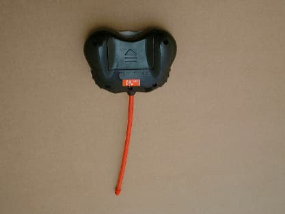
NF260927T
Oct 01, 2001Remote Control Toy Transmitter
Equipment Class
DXX - Part 15 Low Power Communication Device Transmitter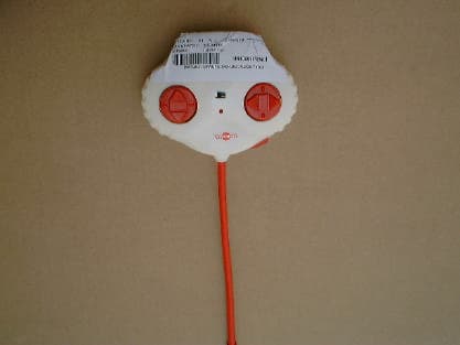
NF260827
Sep 03, 2001Remote Control Toy Transmitter
Equipment Class
DXX - Part 15 Low Power Communication Device Transmitter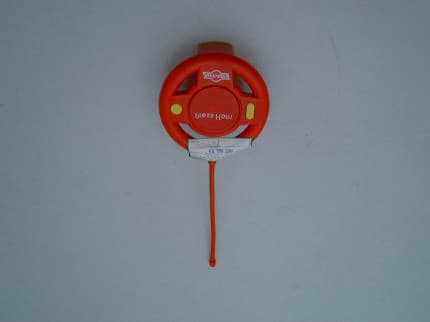
NF250227
Apr 10, 2001Remote Control Toy Transmitter
Equipment Class
DXX - Part 15 Low Power Communication Device Transmitter