NHVWB1U215Car Security
Tohoku Alps Co Ltd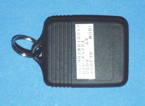
Click to zoom
Application Details
- Equipment Class
- DSC - Part 15 Security/Remote Control Transmitter
- Date of Grant
- Jul 02, 2000
- Application Purpose
- Original Equipment
- Date of Application
- Jun 28, 2000
- Equipment Note
- Car Security
- Frequency Range
- 314.50000000 - 315.50000000
- Company
- Tohoku Alps Co Ltd
- Country
- Japan
Documents & Files
Document Text
Text extracted from the exhibit documents filed with the FCC. Open a document above to read the original.
External Photos
Front View Rear View Case Insert
Internal Photos
Circuit Board, Bottom Circuit Board, Top Inside Case, Front Inside Case, Back/Battery
Test Report
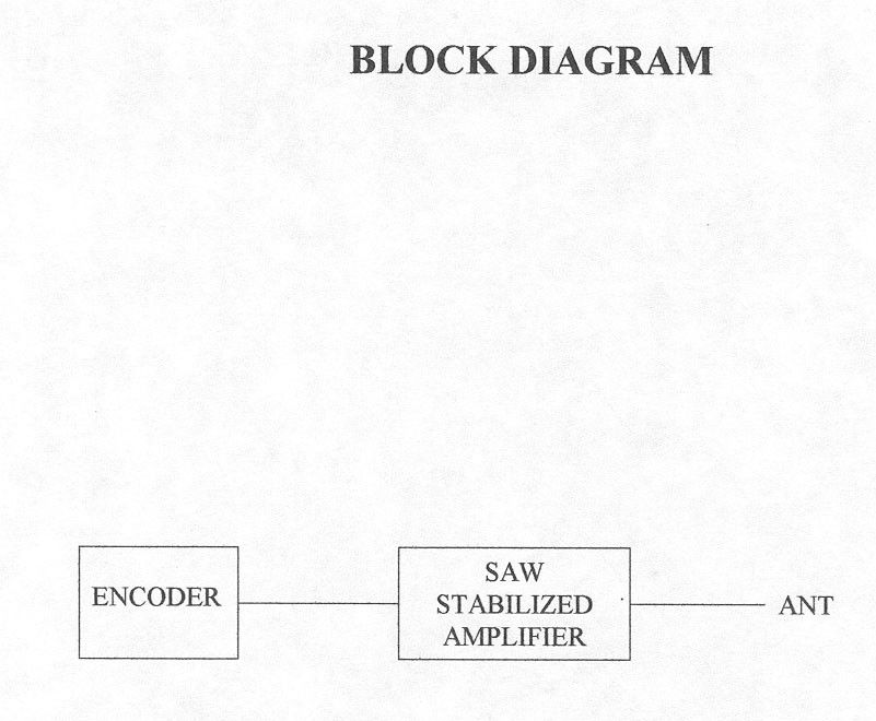
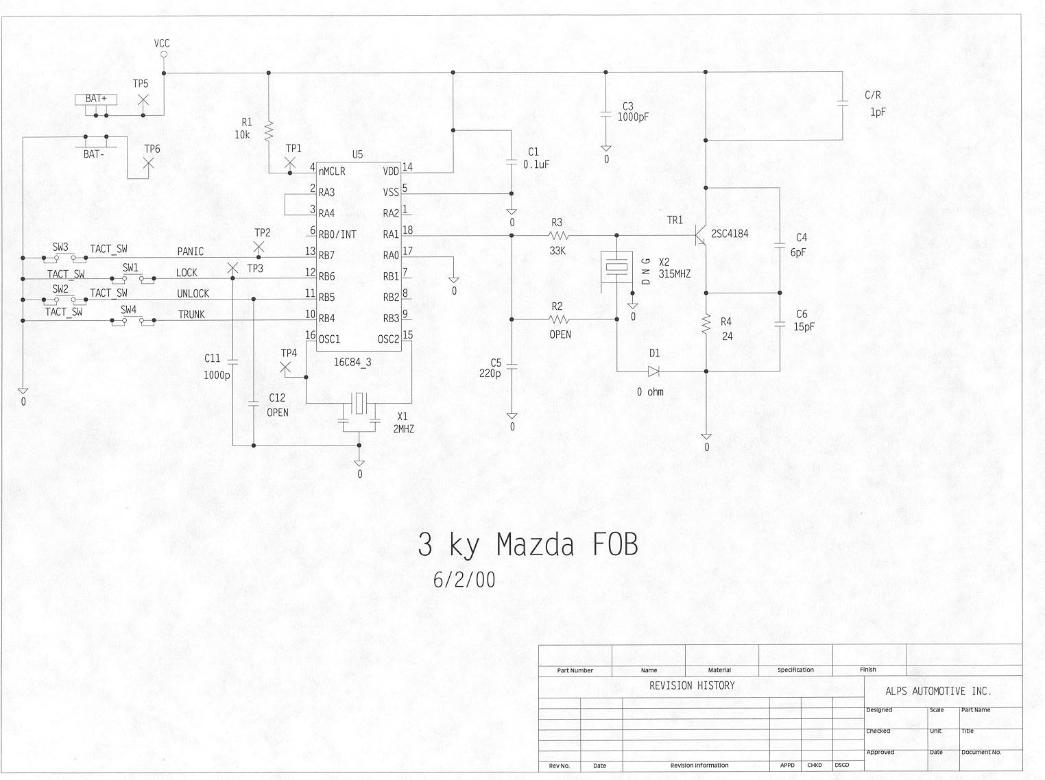
ENGINEERING STATEMENT IN REGARD TO MEASUREMENTS ON Tohoku Alps Co., Ltd. FCC ID: NHVWB1U215 A. INTRODUCTION Hyak Laboratories Inc. has been authorized by Tohoku Alps Co., Ltd., to perform measurements on a transmitter to determine compliance with FCC Rules, Subpart C. The device is a low powered, battery operated transmitter designed for remote control of automobile security systems. It operates at a nominal 315 MHz frequency. The transmitter, con- structed on an etched circuit card, is powered from a 3 volt lithium battery. An integral, etched-circuit antenna is used. The device meets the provisions of Para. 15.231(a)(1) since it is a manually operated device used for alarm system control, and automatically ceases transmission within 5 seconds of push-button switch release. B. DESCRIPTION OF MEASUREMENT FACILITIES A description of the Hyak Laboratories Inc. radiation test facility is a matter of record with the FCC. The facility was accepted for radiation measurements on October 1, 1976, and is currently listed as an acceptable site. C. DESCRIPTION OF MEASUREMENT PROCEDURE: RADIATED MEASUREMENTS Measurements of transmitter radiation field strength were made using ANSI C63.4 (1992) as the test procedure. Measurements were made with 3 meter spacing between the transmitter under test and the test equipment antenna. The transmitter under test was placed on a rotatable table approximately 80 cm in height. The power supply was a fresh battery. C. DESCRIPTION OF MEASUREMENT PROCEDURE: RADIATED MEASUREMENTS (Continued) Measurement of field strength was made through use of HP 8596E and Tektronix 494P spectrum analyzers in conjunction with a HP 8447D and Avantek wide band, low noise preamplifiers; and an Advantest R3361A spectrum analyzer with quasi-peak detector. Singer DM-105A series calibrated dipoles were used as the test antennas in the 25-1000 MHz range. An EMCO 3115 calibrated horn antenna was used between 1 and 4.4 GHz. An analysis of time domain measurements (see plots in Figures 1, 2, and 3) was made to determine average field intensity of the fundamental and any harmonics outside of forbidden bands. Sample calculations are included in Figure 4. Based on time domain observations, and using the procedures of Figure 4, a correction factor for a nominal 100 mS averaging interval was computed. Data for radiated emissions in Table 1 includes this correc- tion factor. For emissions that fell in forbidden bands below 1 GHz the CISPR quasi-peak detector was used. For each spurious emission identified between 30 MHz to the tenth harmonic the test assembly was rotated for maximum pickup, the test antenna varied in elevation and the test antenna polari- zation shifted between horizontal to vertical in order to maximize observed signals. The measurement procedure included recording the worst-case field strength for receiving antenna polarization, test antenna height variation from 3 feet to 10 feet, test sample rotation, and placing the test sample on each of its major planes. The spectrum was checked from 30 MHz to the tenth harmonic. All emissions not reported were more than 20 dB below the permitted level or below FCC limits but in the ambient/system noise floor. Tabulation of the measurements are shown in Table 1. Specific forbidden band scans were made per Paragraph 15.205 and 15.209. D. REPORT OF RADIATED MEASUREMENTS Table 1 lists the frequency and amplitude of all signals observed from 30 MHz to the tenth harmonic that were within 20 dB of the limits of FCC Rules. The averaging factor is included as noted. 2 COMPLETE WORD TRANSMISSION Horizontal: 100 milliseconds/Div Vertical: 10 dB/Div. Resolution: 10 kHz (Time domain) PULSE CHARACTERISTICS FCC ID: NHVWB1U215 FIGURE 1 3 COMPLETE WORD DETAIL Horizontal: 10 milliseconds/Div Vertical: 10 dB/Div. Resolution: 100 kHz (Time domain) PULSE CHARACTERISTICS FCC ID: NHVWB1U215 FIGURE 1 4 WORD BIT DETAIL Horizontal: 2 milliseconds/Div Vertical: 10 dB/Div. Resolution: 100 kHz (Time domain) PULSE CHARACTERISTICS FCC ID: NHVWB1U215 FIGURE 1 5 SAMPLE COMPUTATIONS Using the time domain plots of Figures 1 through 3, maximum "on" time over any 100 mS interval is: Pulses: “Long” 1.2mSx19 = 2.28 “Short” 0.4mSx30 = 12___ 14.28 Duty Cycle: 14.28/100 = 0.14 20 Log 0.14 = 17 dB SAMPLE COMPUTATIONS FCC ID: NHVWB1U215 FIGURE 4 6 TABLE 1 RADIATED FIELD INTENSITY Measured at 3 meters 15.231(b) Meter 1 Antenna Field 2 Calc. Field 3 Frequency Reading Factor Intensity Intensity FCC Limit dB to (MHz) (dBm) (dB) uV/m @ 3m uV/m @ 3m uV/m @ 3m Limit 314.984 -54.0 21.8 5495.4 776.2 6041.0 -17.8 629.968 -86.0 28.5 298.5 42.2 604.1 -23.1 944.952 -86.8 32.6 436.5 61.7 604.1 -19.8 1259.934 -91.2 25.1 110.9 15.7 604.1 -31.7 1574.916 -90.4 26.1 136.5 19.3 500.0* -28.3 1889.904 -100.0 27.7 54.3 7.7 604.1 -37.9 2204.882 -94.8 28.8 112.2 15.8 500.0* -30.0 2519.866 -97.6 29.6 89.1 12.6 604.1 -33.6 2834.850 -84.4 30.4 446.7 63.1 500.0* -18.0 3149.834 -87.2 31.3 358.9 50.7 604.1 -21.5 Note 1: Peak detector reading without averaging. Note 2: uV/m = Log - 1dBu/m 20 dBu = dBm + antenna factor + 107 Note 3: Field Intensity calculated from peak value and -17 dB peak/average factor. *Forbidden Band All other emissions to the tenth harmonic were below FCC limits. (Unit was measured on 3 major planes) RBW: 100 kHz to 1 GHz; 1 MHz if > 1GHz (Measured at 1 m extrapo- lated to 3 m). No video filtering. Peak responding, rms calibrated detector. RADIATED FIELD INTENSITY FCC ID: NHVWB1U215 TABLE 1 7 D. FORBIDDEN BAND MEASUREMENTS Any spurious signals from the transmitter that fell in a forbidden band are identified in Table 1. All forbidden bands, per Paragraph 15.205, from 73 MHz to 4.4 GHz were searched and any applicable emissions above noise or interference levels are shown in Table 1. E. OCCUPIED BANDWIDTH A plot of occupied bandwidth is shown in Figure 5. The device meets bandwidth restriction of Paragraph 15.231(c); 26 dB points are less than 50 kHz with worst-case modulation. (Limit is 0.25% o…
Text truncated - open the document above for the full version.
Test Setup Photos
Test Set- Up
Contact Information
Applicant
Tom Takata
81 229 233111Fax: 81 229 229997
Technical Specifications
| # | Rule Parts | Frequency Range | Power Output |
|---|---|---|---|
| 1 | 15.231 | 314.5 MHz - 315.5 MHz | - |
Other Applications from Tohoku Alps Co Ltd
NHVWZU11
Jul 08, 2003Remote Control for the Vehicle
Equipment Class
DSC - Part 15 Security/Remote Control Transmitter
NHVWBU613
Jun 19, 2003Passive Entry System
Equipment Class
DSR - Part 15 Remote Control/Security Device Transceiver
NHVWBU614
Jun 19, 2003Passive Entry System
Equipment Class
DSR - Part 15 Remote Control/Security Device Transceiver
NHVWDU614
Jun 16, 2003Passive Entry System
Equipment Class
DCD - Part 15 Low Power Transmitter Below 1705 kHz
NHVWDU613
Jun 11, 2003Passive Entry System
Equipment Class
DCD - Part 15 Low Power Transmitter Below 1705 kHz