NHVWBJ443Keyless Remote
Tohoku Alps Co Ltd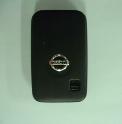
Click to zoom
Application Details
- Equipment Class
- DSC - Part 15 Security/Remote Control Transmitter
- Date of Grant
- Feb 07, 2003
- Application Purpose
- Original Equipment
- Date of Application
- Feb 04, 2003
- Equipment Note
- Keyless Remote
- Frequency Range
- 312.12500000 - 312.12500000
- Company
- Tohoku Alps Co Ltd
- Country
- Japan
Documents & Files
Document Text
Text extracted from the exhibit documents filed with the FCC. Open a document above to read the original.
Users Manual
Document No. Title Page 5AX000XX00 Product Specification Background Passive Entry System FORMAT NO. FIRMWARE_A(VER 0.01) CONTENTS 1. PREFACE.................................................................................................................................4 2. PASSSIVE ACCSESS ENTRY FUNCTIONALITY.....................................................................5 2.1. Door Unlocking..............................................................................................................................................5 2.2. Engine Start...................................................................................................................................................6 2.3. Engine Stop....................................................................................................................................................6 2.4. Door Locking (Push switch)..........................................................................................................................7 3. ACTIVE ACCESS ENTRY FUNCTIONALITY............................................................................8 3.1. Door Unlocking..............................................................................................................................................8 3.2. Engine Start...................................................................................................................................................8 3.3. Engine Stop....................................................................................................................................................8 3.4. Door Locking..................................................................................................................................................8 4. ENTRY SYSTEM OPTIONS......................................................................................................9 4.1. System Schematic.........................................................................................................................................9 4.2. Modules..........................................................................................................................................................9 4.2.1. FOB ECU................................................................................................................................................9 4.2.2. Entry System ECU..................................................................................................................................9 5. SYSTEM CHARACTERISTICS...............................................................................................10 5.1. Antenna Areas.............................................................................................................................................10 5.2. Exciter Locations.........................................................................................................................................11 5.3. Switch Input Locations (Door handle, Touch sensor)................................................................................12 6. ELECTRICAL CHARACTERISTICS.......................................................................................13 6.1. FOB..............................................................................................................................................................13 6.2. Entry System ECU.......................................................................................................................................13 Document No. Title Page 5AX000XX00 Product Specification Background Passive Entry System FORMAT NO. FIRMWARE_A(VER 0.01) 1. Preface This document describes the requirements and operation of the Passive Entry System. However, this document is especially for the Entry system ECU (acronym for Electric Control Unit) and the FOB. The FOB consists the following functionality for passive access and active access: • Door unlocking / locking (however, only for request by means of switch operation) • Trunk unlocking / locking (however, only for request by means of switch operation) • LF decoding • RF encoding • Communication data encryption (cryptograph, anti-collision, rolling code and stuff) And the entry system ECU consists of the following functionality: • Door unlocking / locking • Trunk unlocking / locking • Engine start (/ stop) • LF encoding • RF encoding • Communication data encryption (cryptograph, anti-collision, rolling code and stuff) • LF antenna unit control • Communication with the node ECUs connected to the body bus (e.g. CAN, J1850, customer dependent bus) As a further function, both the FOB and the entry system ECU provides the following function: • Learning mode for programming the manufacturing data and stuff • Data locking and password protection • Diagnostic (based upon ISO9141 if required) Document No. Title Page 5AX000XX00 Product Specification Background Passive Entry System FORMAT NO. FIRMWARE_A(VER 0.01) 2. Passsive Accsess Entry Functionality A proximity sensor located on, for example the door handles, mirrors and trunk lid will be used for proximity check if user is in neighborhood of the vehicle. The switch input will trigger for unlocking and open the doors and trunk. Figure 1 2.1.Door Unlocking • User pull / touch the door handle (sensing of door handle switch). • ECU sends LF-challenge via exterior antenna. • FOB sends RF-response to the ECU. • Door unlocking status is engaged. • Doors are opened. Figure 2 Proximity sensor Switch input (door handle) LF RF FOB Document No. Title Page 5AX000XX00 Product Specification Background Passive Entry System FORMAT NO. FIRMWARE_A(VER 0.01) 2.2.Engine Start • User pushes / operate the engine start button / knob. • ECU sends LF-challenge via interior antenna. • FOB sends RF-response to the ECU. • Immobilizer ECU receives and authorize the response. • Engine controller ECU receives the author…
Text truncated - open the document above for the full version.
Cover Letter(s)
American Telecommunications Certification Body Inc. 6731 Whittier Ave, McLean, VA 22101 January 24, 2003 RE: TOHOKU ALPS CO., LTD. FCC ID: NHVWBJ443 After a review of the submitted information, I have a few comments on the above referenced Application. 1) Please provide a higher resolution exhibit for the FCC Labeling. The FCC ID can not be easily read in the exhibit provided. 2) Page 7 of 8 of the operational description mentions 16 seconds due to manual press of the switch. It is unclear what the 16 seconds refers to. Note that the device must stop transmitting in less than 5 seconds after released (15.231(a)(1)). Please provide a better explanation of what the16 seconds refers to. Additionally, please confirm how fast the device deactivates after being released. 3) The test report shows an automatic deactivation. However it can not be determined if the pulse provided is a single packet of data or the end of transmission. Please provide an additional plot that shows the deactivation over 5 seconds or more. 4) This device appears to automatically transmit due to various commands received via 125 kHz LF. However, there is not information regarding what is transmitted by the 312 MHz TX in response to the 125 kHz signal. Please provide a detailed explanation of the data sent by the 312 MHz TX in response to the 125 kHz transmission. Is the data sent equivalent to the data sent during manual activation? Additionally, how long does the device transmit upon receiving a command? Note that the device must stop transmitting in less than 5 seconds after automatically being activated (15.231(a)(2)). 5) Please provide a better explanation of what the rolling code is. Note that since the code is not set, it could be considered data. Please provide a detailed explanation of what this is. Please note that data transmissions are subject to 15.231(e) which has particular timing requirements as well. 6) The schematics provided were unclear. It also appears that the schematic does not contain any values but only reference designators. Please note that the schematic must contain physical values. 7) The 731 form section III, 7 mentions this is part of a system that operates with another device, therefore, please fill out section 8. Timothy R. Johnson Examining Engineer mailto: [email protected] The items indicated above must be submitted before processing can continue on the above referenced application. Failure to provide the requested information may result in application termination. Correspondence should be considered part of the permanent submission and may be viewed from the Internet after a Grant of Equipment Authorization is issued. Please do not respond to this correspondence using the email reply button. In order for your response to be processed expeditiously, you must submit your documents through the AmericanTCB.com website. Also, please note that partial responses increase processing time and should not be submitted. Any questions about the content of this correspondence should be directed to the sender.
Cover Letter(s)
Dear Tim, Thank you very much for your contact on the above application. I make a reply as follow: 1. Please see the file "Revised label". 2. As you can see on the timing chart, "16 seconds" mean that the transmission is stopped in 16 seconds maximum when Switch is kept pushing. When the user release his hand, transmission is stopped within "0.5 seconds" after he released his hand. 3. Please see the file "page 16 REVISED". Please replace the previous Page 16 with this. 4. As for the explanation for the data sent by the 312 MHz Tx in response to the 125kHz transmission, please see the file "RF response". >Is the data sent equivalent to the data sent during manual activation? --->> Basically, it's equivalent. During the button is pushed, same data is continuously transmitted. >How long does the device transmit upon receiving the command? --->> About 50mS transmission. The longest data transmission is less than 50mS. 5. Please see the last page of the file "RF response". To improve the security, the counter comprising of 20 bits is incremental by one at each LF transmission. This bit code indicates "Rolling code" The RF response format of transmission comprises preamble of 16 bits, sync of 2 bits, start bit of 1 bit, response code of 32 bits, fixed code of 35 bits and stop bit of 1 bit. Function code and disc code in the response code are not used in this application. The Rolling code" is a part of an encryption data consisting of 20 bits in the response code and increments the data by one from "00000" to "FFFFF" every transmission or reception. When the data reaches "FFFFF", it returns "00000" again. The addition of the rolling code not only improves the transmitted data with regard to security performance but also constitutes a part of the transmitted recognition code. 1> The transmission of recognition code is not prohibited in the Section 15.231(a) due to above description with regard to the RF response format. 2> Since the transmission of recognition code automatically ceases within 0.5 second after being released the activation of the transmitter in case To: "Timothy R. Johnson" <[email protected]> cc: Tim Johnson <[email protected]> Subject: Re: Review of FCC ID: NHVWBJ443 2/5/2003file://C:\DOCUME~1\TIMOTH~1.JOH\LOCALS~1\Temp\eud9.htm of manual operation, the transmitter operation complies with 15.231(a)(1). 3> Since the transmission activated automatically ceases transmission within 0.5 second after activation, the transmitter operation complies with 15.231(a)(2). 4> Since the transmitter does not periodically operate, the transmitter operation complies with 15.231(a)(3). As a result, this transmitter complies with all the requirements in 15.231(a). 6. Please see the file "SystemBlock" and "Schematic 2". 7. Please see the file "Revised Form 731". Best regards, Yukie Koyama ::::::::::::::::::::::::::::: EMC Head Office Division A-Pex International Co.,Ltd. 4383-326 Asama-cho Ise-shi Mie-ken 516-0021 JAPAN TEL +81-596-24-8116 FAX +81-596-24-8124 E-mail:[email protected] ::::::::::::::::::::::::::::: --Original Message 2003/01/25 3:07:36-- Yoshiyuki/Yukie, Attached are comments regarding review of this application. Please provide information as soon as possible. Thank You, Timothy R. Johnson, NARTE Certified EMC Engineer (No. EMC-002205-NE) Timothy R. Johnson, NARTE Certified EMC Engineer (No. EMC-002205-NE) Examining Engineer American TCB, Inc. 6731 Whittier Ave. McLean, VA 22101 email: [email protected] alternate email: [email protected] direct number: 404-414-8071 corporate phone: 703-847-4700 corporate fax: 703-847-6888 - ATCB Comments_012403.pdf 2/5/2003file://C:\DOCUME~1\TIMOTH~1.JOH\LOCALS~1\Temp\eud9.htm
Cover Letter(s)
Tim, Could you confirm the following answer? >The automatic deactivation in the report shows about 300 ms. Is this for >manual mode? ---->> Yes, this is manual mode. >If so, please provide a plot that shows deactivation in < 50 msec as >specified below for transmissions in response to the 125 kHz signal. ---->> Please find attached file. This is data for transmissions in response to the 125 kHz signal. RFEN is a output carrier, and the data is modulated with "FSK". In front of this data, there is about 2mS's signal. This signal is called "anti-collision" and is used for the confirmation which Hand Unit answered. <Since one control unit can register 4 hand unit max, data causes interference if they answer at the same time.> The above answer is acceptable? I hope the grant is issued with this. Thank you very much. Best regards, Yukie Koyama ::::::::::::::::::::::::::::: EMC Head Office Division A-Pex International Co.,Ltd. 4383-326 Asama-cho Ise-shi Mie-ken 516-0021 JAPAN TEL +81-596-24-8116 FAX +81-596-24-8124 E-mail:[email protected] ::::::::::::::::::::::::::::: --Original Message 2003/02/06 7:20:50-- Yukie, The automatic deactivation in the report shows about 300 ms. Is this for manual mode? If so, please provide a plot that shows deactivation in < 50 msec as specified below for transmissions in response to the 125 kHz signal. Thank You, To: "Timothy R. Johnson" <[email protected]> Subject: Re: Review of FCC ID: NHVWBJ443 Page 1 In Printed for "Timothy R. Johnson" <[email protected]>
External Photos
TOHOKU ALPS CO.,LTD Hand Unit of Passive Entry System FCC ID: NHVWBJ443 <External photos> Front view TOHOKU ALPS CO.,LTD Hand Unit of Passive Entry System FCC ID: NHVWBJ443 Rear view
Internal Photos
TOHOKU ALPS CO.,LTD Hand Unit of Passive Entry System FCC ID: NHVWBJ443 <Internal photos> Inside view TOHOKU ALPS CO.,LTD Hand Unit of Passive Entry System FCC ID: NHVWBJ443 Circuit board<front> TOHOKU ALPS CO.,LTD Hand Unit of Passive Entry System FCC ID: NHVWBJ443 Circuit board<rear >
Test Report
Tim, Could you confirm the following answer? >The automatic deactivation in the report shows about 300 ms. Is this for >manual mode? ---->> Yes, this is manual mode. >If so, please provide a plot that shows deactivation in < 50 msec as >specified below for transmissions in response to the 125 kHz signal. ---->> Please find attached file. This is data for transmissions in response to the 125 kHz signal. RFEN is a output carrier, and the data is modulated with "FSK". In front of this data, there is about 2mS's signal. This signal is called "anti-collision" and is used for the confirmation which Hand Unit answered. <Since one control unit can register 4 hand unit max, data causes interference if they answer at the same time.> The above answer is acceptable? I hope the grant is issued with this. Thank you very much. Best regards, Yukie Koyama ::::::::::::::::::::::::::::: EMC Head Office Division A-Pex International Co.,Ltd. 4383-326 Asama-cho Ise-shi Mie-ken 516-0021 JAPAN TEL +81-596-24-8116 FAX +81-596-24-8124 E-mail:[email protected] ::::::::::::::::::::::::::::: --Original Message 2003/02/06 7:20:50-- Yukie, The automatic deactivation in the report shows about 300 ms. Is this for manual mode? If so, please provide a plot that shows deactivation in < 50 msec as specified below for transmissions in response to the 125 kHz signal. Thank You, To: "Timothy R. Johnson" <[email protected]> Subject: Re: Review of FCC ID: NHVWBJ443 Page 1 of 4In 2/8/2003Printed for "Timothy R. Johnson" <[email protected]> Tim At 03:29 AM 2/5/2003, you wrote: >Dear Tim, > >Thank you very much for your contact on the above application. I make a >reply as follow: > >1. Please see the file "Revised label". > >2. As you can see on the timing chart, "16 seconds" mean that the >transmission is stopped in 16 seconds maximum when Switch is kept pushing. >When the user release his hand, transmission is stopped within "0.5 >seconds" after he released his hand. > >3. Please see the file "page 16 REVISED". Please replace the previous Page >16 with this. > >4. As for the explanation for the data sent by the 312 MHz Tx in response >to the 125kHz transmission, please see the file "RF response". > > >Is the data sent equivalent to the data sent during manual activation? >--->> Basically, it's equivalent. During the button is pushed, same data is >continuously transmitted. > > >How long does the device transmit upon receiving the command? >--->> About 50mS transmission. The longest data transmission is less than >50mS. > >5. Please see the last page of the file "RF response". To improve the >security, the counter comprising of 20 bits is incremental by one at each >LF transmission. This bit code indicates "Rolling code" > >The RF response format of transmission comprises preamble of 16 bits, sync >of 2 bits, start bit of 1 bit, response code of 32 bits, fixed code of 35 >bits and stop bit of 1 bit. Function code and disc code in the response >code are not used in this application. The Rolling code" is a part of an >encryption data consisting of 20 bits in the response code and increments >the data by one from "00000" to "FFFFF" every transmission or reception. >When the data reaches "FFFFF", it returns "00000" again. The addition of Page 2 of 4In 2/8/2003Printed for "Timothy R. Johnson" <[email protected]> >the rolling code not only improves the transmitted data with regard to >security performance but also constitutes a part of the transmitted >recognition code. > >1> The transmission of recognition code is not prohibited in the Section >15.231(a) due to above description with regard to the RF response format. >2> Since the transmission of recognition code automatically ceases within >0.5 second after being released the activation of the transmitter in case >of manual operation, the transmitter operation complies with 15.231(a)(1). > >3> Since the transmission activated automatically ceases transmission >within 0.5 second after activation, the transmitter operation complies with >15.231(a)(2). > >4> Since the transmitter does not periodically operate, the transmitter >operation complies with 15.231(a)(3). > >As a result, this transmitter complies with all the requirements in >15.231(a). > >6. Please see the file "SystemBlock" and "Schematic 2". > >7. Please see the file "Revised Form 731". > >Best regards, > >Yukie Koyama >::::::::::::::::::::::::::::: >EMC Head Office Division >A-Pex International Co.,Ltd. >4383-326 Asama-cho Ise-shi >Mie-ken 516-0021 JAPAN >TEL +81-596-24-8116 >FAX +81-596-24-8124 >E-mail:[email protected] >::::::::::::::::::::::::::::: > >--Original Message 2003/01/25 3:07:36-- >Yoshiyuki/Yukie, > >Attached are comments regarding review of this application. Please >provide information as soon as possible. > >Thank You, > >Timothy R. Johnson, NARTE Certified EMC Engineer (No. EMC-002205-NE) > >Timothy R. Johnson, NARTE Certified EMC Engineer (No. EMC-002205-NE) Page 3 of 4In 2/8/2003Printed for "Timothy R. Johnson" <[email protected]> >Examining Engineer >American TCB, Inc. >6731 Whittier Ave. >McLean, VA 22101 > >email: [email protected] >alternate email: [email protected] >direct number: 404-414-8071 >corporate phone: 703-847-4700 >corporate fax: 703-847-6888 > - ATCB Comments_012403.pdf (See attached file: Data.pdf) Data1.pdf Page 4 of 4In 2/8/2003Printed for "Timothy R. Johnson" <[email protected]>
Test Setup Photos
Test report No. : 23EE0005-HO-5 Page : 12 of 16 FCC ID : NHVWBJ443 Issued date : January 22, 2003 A-Pex International Co., Ltd. EMC Head Office Division. 4383-326 Asama-cho, Ise-shi, Mie-ken 516-0021 JAPAN Telephone : +81 596 24 8116 Facsimile : +81 596 24 8124 APPENDIX 1: Photographs of test setup Radiated emission
Contact Information
Applicant
Tom Takata
81 229 233111Fax: 81 229 229997
Technical Contact
A-Pex International Co., Ltd.Yoshiyuki Iwasa
[email protected]+81-596-24-8116
4383-326 Asama-cho · Ise-shi, Mie-ken · Japan
Non-Technical Contact
A-Pex International Co., Ltd.Yukie Koyama
[email protected]+81-596-24-8116
Test Firm
UL Apex Co., Ltd.Tetsuya Hashimoto
Technical Specifications
| # | Rule Parts | Frequency Range | Power Output |
|---|---|---|---|
| 1 | 15.231 | 312.125 MHz - 312.125 MHz | - |
Other Applications from Tohoku Alps Co Ltd
NHVWZU11
Jul 08, 2003Remote Control for the Vehicle
Equipment Class
DSC - Part 15 Security/Remote Control Transmitter
NHVWBU613
Jun 19, 2003Passive Entry System
Equipment Class
DSR - Part 15 Remote Control/Security Device Transceiver
NHVWBU614
Jun 19, 2003Passive Entry System
Equipment Class
DSR - Part 15 Remote Control/Security Device Transceiver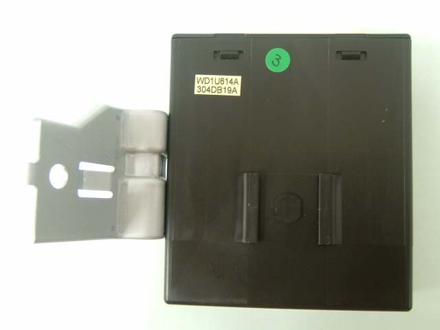
NHVWDU614
Jun 16, 2003Passive Entry System
Equipment Class
DCD - Part 15 Low Power Transmitter Below 1705 kHz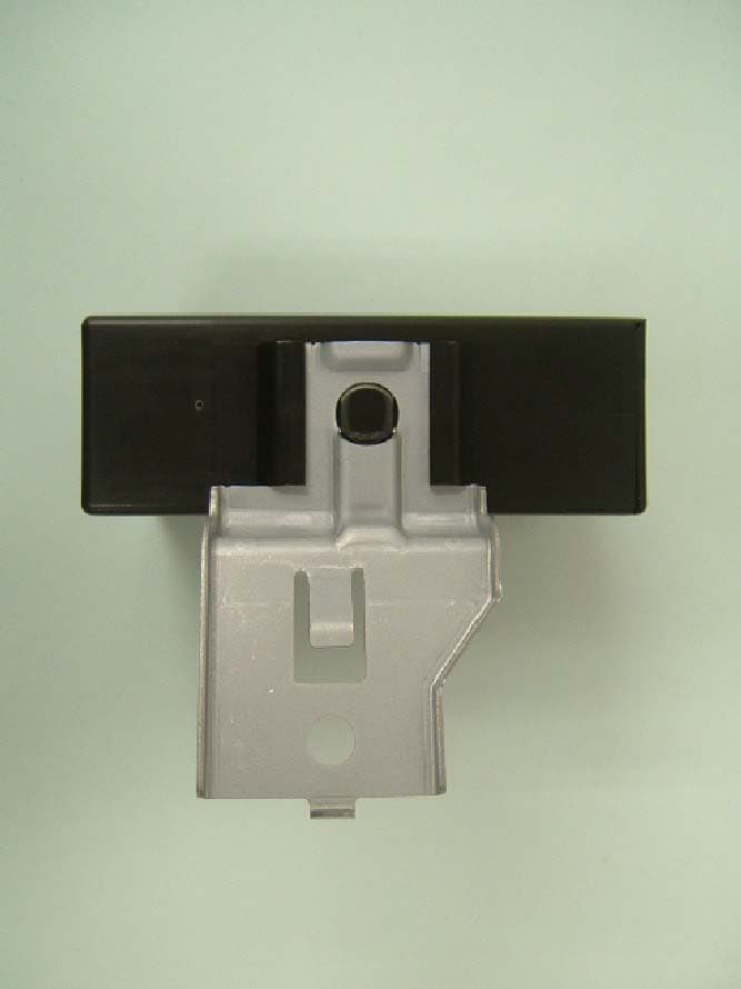
NHVWDU613
Jun 11, 2003Passive Entry System
Equipment Class
DCD - Part 15 Low Power Transmitter Below 1705 kHz