NHVWBU612Passive Entry System
Tohoku Alps Co Ltd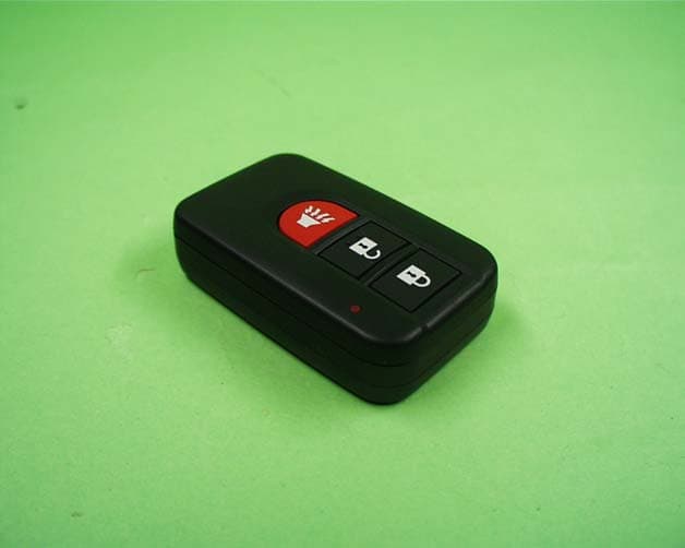
Click to zoom
Application Details
- Equipment Class
- DSR - Part 15 Remote Control/Security Device Transceiver
- Date of Grant
- Nov 14, 2002
- Application Purpose
- Original Equipment
- Date of Application
- Nov 14, 2002
- Equipment Note
- Passive Entry System
- Frequency Range
- 433.92000000 - 433.92000000
- Company
- Tohoku Alps Co Ltd
- Country
- Japan
Documents & Files
Document Text
Text extracted from the exhibit documents filed with the FCC. Open a document above to read the original.
Users Manual
Document No. Title Page 5AX000XX00 Product Specification Background Passive Entry System FORMAT NO. FIRMWARE_A(VER 0.01) 1. Preface This document describes the requirements and operation of the Passive Entry System. However, this document is especially for the Entry system ECU (acronym for Electric Control Unit) and the FOB. The FOB consists the following functionality for passive access and active access: • Door unlocking / locking (however, only for request by means of switch operation) • Trunk unlocking / locking (however, only for request by means of switch operation) • LF decoding • RF encoding • Communication data encryption (cryptograph, anti-collision, rolling code and stuff) And the entry system ECU consists of the following functionality: • Door unlocking / locking • Trunk unlocking / locking • Engine start (/ stop) • LF encoding • RF encoding • Communication data encryption (cryptograph, anti-collision, rolling code and stuff) • LF antenna unit control • Communication with the node ECUs connected to the body bus (e.g. CAN, J1850, customer dependent bus) As a further function, both the FOB and the entry system ECU provides the following function: • Learning mode for programming the manufacturing data and stuff • Data locking and password protection • Diagnostic (based upon ISO9141 if required) Document No. Title Page 5AX000XX00 Product Specification Background Passive Entry System FORMAT NO. FIRMWARE_A(VER 0.01) 2. Passsive Accsess Entry Functionality A proximity sensor located on, for example the door handles, mirrors and trunk lid will be used for proximity check if user is in neighborhood of the vehicle. The switch input will trigger for unlocking and open the doors and trunk. Figure 1 2.1.Door Unlocking • User pull / touch the door handle (sensing of door handle switch). • ECU sends LF-challenge via exterior antenna. • FOB sends RF-response to the ECU. • Door unlocking status is engaged. • Doors are opened. Figure 2 Proximity sensor Switch input (door handle) LF RF FOB Document No. Title Page 5AX000XX00 Product Specification Background Passive Entry System FORMAT NO. FIRMWARE_A(VER 0.01) 2.2.Engine Start • User pushes / operate the engine start button / knob. • ECU sends LF-challenge via interior antenna. • FOB sends RF-response to the ECU. • Immobilizer ECU receives and authorize the response. • Engine controller ECU receives the authorization for engine strat. • Start the engine. Figure 3 2.3.Engine Stop • User pushes / operate the engine stop button / knob. • ECU communicates with the other ECU for engine start request. • Engine controller ECU receives the request. • Stop the engine Figure 4 LF RF FOB Document No. Title Page 5AX000XX00 Product Specification Background Passive Entry System FORMAT NO. FIRMWARE_A(VER 0.01) 2.4.Door Locking (Push switch) • User closes the door and pushes the switch (sensing of door locking switch). • ECU sends LF-challenge via exterior antenna. • FOB sends RF-response to the ECU. • Door locking status is engaged. • Doors are locked. • (Indicates the door locking status by means of Flasher / Buzzer or stuff) Figure 5 Document No. Title Page 5AX000XX00 Product Specification Background Passive Entry System FORMAT NO. FIRMWARE_A(VER 0.01) 3. Active Access Entry Functionality 3.1.Door Unlocking Same functionality as the current one. 3.2.Engine Start This function does not effect on the active entry system. 3.3.Engine Stop This function does not have influencei on the active entry system. 3.4.Door Locking Same functionality as the current one. Document No. Title Page 5AX000XX00 Product Specification Background Passive Entry System FORMAT NO. FIRMWARE_A(VER 0.01) 4. Entry System Options 4.1.System Schematic 4.2.Modules 4.2.1.FOB ECU 4.2.2.Entry System ECU FOB OTHER ECUS LF (>2Kbps) RF (>4Kbps) Local Bus ECU1 ECU2 ECU3 Body Bus ENTRY SYSTEM ECU FOB ENTRY SYSTEM ECU RF Amp LF Amp ASIC Z X Y Lock Unlock Trunk Key lock Emergency key (Transponder) MCU FT handle BT handle FH handle BH handle Trunk lid Engine start Body Bus Local Bus RF Amp LF Exciter LF Exciter LF Exciter LF Exciter LF Exciter LF Exciter Interior FT BT FH BH Trunk 125kHz 433.92 MHz 125kHz 433.92 MHz 433.92M Hz 125kHz Document No. Title Page 5AX000XX00 Product Specification Background Passive Entry System FORMAT NO. FIRMWARE_A(VER 0.01) 5. System Characteristics 5.1.Antenna Areas Exterior operating range: 0.8m to 1.5m Interior operating range: Only inside the car Number of the exterior exciters : max. 5 (min. 2), however, it is depending on the type of the vehicle. Number of the interior exciters: 1 (1-Dimmension) or 2 (2-Dimension required) Figure 6 Exterior antenna functionality: • Unlock / lock doors and trunk. • Activate / deactivate alarm system. • Activate immobilizer Interior antenna functionality: • Deactivate immobilizer • Engine start Exterior Interior FT BT Document No. Title Page 5AX000XX00 Product Specification Background Passive Entry System FORMAT NO. FIRMWARE_A(VER 0.01) 5.2.Exciter Locations Exterior exciters: 2 doors and 1 trunk Interior exciters: 1 driver’s sheet 2 column / shift lever (X-Y 2-Dimension) Figure 7 Antenna location can be different among of type of the vehicle (e.g. coupe, sedan, mini and stuff). Exterior Interior FT BT Document No. Title Page 5AX000XX00 Product Specification Background Passive Entry System FORMAT NO. FIRMWARE_A(VER 0.01) 5.3.Switch Input Locations (Door handle, Touch sensor) There are some kind of sensors, for instance the door handle contact switch and touch sensor, will be used as a triggering for unlocking and open the door. Switch inputs: 2 doors and 1 trunk Figure 8 Switch inputs can be different among of type of the vehicle (e.g. coupe, sedan, mini and stuff). FT BT Document No. Title Page 5AX000XX00 Product Specification Background Passive Entry System FORMAT NO. FIRMWARE_A(VER 0.01) 6. Electrical Characteristics 6.1.FOB • ASK / FSK modulation • Operating supply voltage 2.1V to 4.0V (3.0V Battery) • Operating supply current < 7mA •…
Text truncated - open the document above for the full version.
External Photos
External Photo TOHOKU ALPS CO., LTD. FCC ID: NHVWBU612 Model: TFWB1U612(Hand Unit) Front View Back View External Photo TOHOKU ALPS CO., LTD. FCC ID: NHVWBU612 Model: TFWB1U612(Hand Unit) Over View
ID Label/Location Info
Label printing Outline FCC ID : NHVWBU612 IC : 3495A-FWB1U612 Label Label materials Surface material : PET (polyethylene terephthalate) Bonding material : Adhesive (PA-T1)
Internal Photos
Internal Photo TOHOKU ALPS CO., LTD. FCC ID: NHVWBU612 Model: TFWB1U612(Hand Unit) Front View Back View Internal Photo TOHOKU ALPS CO., LTD. FCC ID: NHVWBU612 Model: TFWB1U612(Hand Unit) Open View Side View
Operational Description
ALPS ELECTRIC Co., LTD Functional description of blocks . A : LF antenna Block Receiving of LF signal . B : Power supply Block Power supply in a circuit . C : Control and switch input Block Switch input and LF signal input monitoring. RF signal coded. D : RF oscillation and modulation Block Oscillation and Modulation RF signal. E : RF amplifier Block Amplitude RF signal. Circuit Diagram A B C D E
Test Report
Test report No.: 23CE0043-YW-1 Page: 2 of 11 FCC ID: NHVWBU612 Issued date: October 29, 2002 A-pex International Co., Ltd. YOKOWA LAB. 108 Yokowa-cho, Ise-shi, Mie-ken 516-1106 JAPAN Telephone:int +81 596 39 1485 Facsimile: int +81 596 39 0232 CONTENTS PAGE SECTION 1: Client information 3 SECTION 2: Equipment under test (E.U.T.)3 SECTION 3: Test specification, methods & procedures4 SECTION 4: Operation of E.U.T. during testing5 SECTION 5: Summary of test results 6 SECTION 6: Radiated emissions, -20dB BW & Automatically deactivate7 APPENDIX 1: Photographs of test setup9 APPENDIX 2:Test instruments9 APPENDIX 3: Data of EMI test9 Test report No.: 23CE0043-YW-1 Page: 3 of 11 FCC ID: NHVWBU612 Issued date: October 29, 2002 A-pex International Co., Ltd. YOKOWA LAB. 108 Yokowa-cho, Ise-shi, Mie-ken 516-1106 JAPAN Telephone:int +81 596 39 1485 Facsimile: int +81 596 39 0232 SECTION 1: Client information Company name: Tohoku Alps Co., Ltd. Address: 6-3-36 Nakazato, Furukawa-City, Miyagi-pref, 989-6181 Japan Telephone Number: +81 229 23 5111 Facsimile Number: +81 229 22 3755 Contact Person: Tomosuke Takata SECTION 2: Equipment under test (E.U.T.) Type of Equipment: Passive Entry System / (Car Lock / Unlock devices) Tx section Model No.TFWB1U612(Hand Unit) Sample No. No.1 Number of Channel 1 Frequency Characteristics 433.92MHz Modulation FSK(Frequency shift keying) Information antenna Integral / (P.C.B pattern antenna) Rating DC3.0V Lithium Battery (CR2023) Country of Manufacture Japan Rx section Type of Receiver Turned Radio Frequency Receiver Receiving Frequency125kHz Local Oscillator Frequencynone Intermediate Frequencynone Information antennaIntegral / (Loop coil and Bar antenna) RatingDC3.0V Lithium Battery (CR2023) Country of Manufacture: Japan Receipt Date of Sample : October 25, 2002 Condition of EUT: Engineering prototype 2.2Product Description The hand unit of passive entry system is a transmitter of 433.92MHz and a receiver of 125kHz. The control unit of the passive entry system is a transmitter of 125kHz and a receiver of 433.92MHz. These units are the new type of keyless entry system which communicates with each other. See reference our test report No. 23AE0036-YW-2.(Control Unit / FCC ID: NHVWDU61 / Date of Grant: 10/16/2002) Test report No.: 23CE0043-YW-1 Page: 4 of 11 FCC ID: NHVWBU612 Issued date: October 29, 2002 A-pex International Co., Ltd. YOKOWA LAB. 108 Yokowa-cho, Ise-shi, Mie-ken 516-1106 JAPAN Telephone:int +81 596 39 1485 Facsimile: int +81 596 39 0232 SECTION 3: Test specification, methods & procedures 3. 1Test Specification Test Specification: FCC Part 15 Subpart C Title: FCC 47CFR Part15 Radio Frequency Device Subpart C Intentional Radiators Section 15.231 Periodic operation in the band 40.66 – 40.70 MHz and above 70MHz Test Specification: FCC Part 15 Subpart B Section 15.109 Radiated emission limits Title: FCC 47CFR Part15 Radio Frequency Device Subpart B Unintentional Radiators 3.2Methods & Procedures No.ItemTest ProcedureSpecificationRemarks 1Automatically DeactivateANSI C63.4:2000 FCC Section 15.231(a)(1)Radiated 2 Electric Field Strength of Fundamental Emission ANSI C63.4:2000 FCC Section 15.231(b)Radiated 3 Electric Field Strength of Spurious Emission ANSI C63.4:2000 FCC Section 15.205 FCC Section 15.209 FCC Section 15.231(b) Radiated 4-20dB BandwidthANSI C63.4:2000 FCC Section 15.231(c)Radiated 5Radiated emissionANSI C63.4:2000 FCC Section 15.109(a)Radiated 6Conducted EmissionANSI C63.4:2000 FCC Section 15.107(a) and 207 AC Mains only *These tests were performed without any deviations from test procedure except for additions or exclusions. 3.3 Exclusion from standard No.ItemTest ProcedureSpecificationRemarks 6Conducted EmissionANSI C63.4:2000 FCC Section 15.107(a) and 207 This test is not applicable since the EUT does not have AC pwer port. Test report No.: 23CE0043-YW-1 Page: 5 of 11 FCC ID: NHVWBU612 Issued date: October 29, 2002 A-pex International Co., Ltd. YOKOWA LAB. 108 Yokowa-cho, Ise-shi, Mie-ken 516-1106 JAPAN Telephone:int +81 596 39 1485 Facsimile: int +81 596 39 0232 SECTION 4: Operation of E.U.T. during testing 4.1Operating Modes The EUT exercise program used during radiated and conducted testing was designed to exercise the various system components in a manner similar to typical use. The operating mode/system were as follows: Operation mode is as follows; - Transmitting mode - Receiving mode Justification: The system was configured in typical fashion (as a customer would normally use it) for testing. 4.2 Configuration and peripherals Front View (Hand Unit) (A):EUT Top View (Hand Unit) (A):EUT Description of EUT No.ItemModel numberSerial numberManufacturerRemarks A Passive Entry System (Hand Unit) TFWB1U612 Sample No.1&2 Tohoku AlpsEUT Test report No.: 23CE0043-YW-1 Page: 6 of 11 FCC ID: NHVWBU612 Issued date: October 29, 2002 A-pex International Co., Ltd. YOKOWA LAB. 108 Yokowa-cho, Ise-shi, Mie-ken 516-1106 JAPAN Telephone:int +81 596 39 1485 Facsimile: int +81 596 39 0232 SECTION 5: Summary of test results 5.1 Test results No.ItemTest ProcedureSpecificationRemarksResult 1Automatically DeactivateANSI C63.4:2000 Section 15.231(a)(1)Radiated Complied 2 Electric Field Strength of Fundamental Emission ANSI C63.4:2000 FCC Section 15.231(b)Radiated Complied 3 Electric Field Strength of Spurious Emission ANSI C63.4:2000 FCC Section 15.205 FCC Section 15.209 FCC Section 15.231(b) Radiated Complied 4 -20dB BandwidthANSI C63.4:2000 FCC Section 15.231(c)Radiated Complied 5Radiated emissionANSI C63.4:2000 FCC Section 15.109(a)Radiated Complied A-PEX INTERNATIONAL hereby confirms that E.U.T., in the configuration tested, complies with the specifications FCC Part 15 Subpart C Section 15.231 and FCC Part 15 Subpart B Section 15.109(a) 5.2Uncertainty Radiated Emission Test The measurement uncertainty (with a 95% confidence level) for this test using Biconical antenna is ±4.4dB. The measurement uncertainty (with a 95% confidence level) for this test using Logper…
Text truncated - open the document above for the full version.
Test Setup Photos
Test report No.: 23CE0043-YW-1 Page: 8 of 11 FCC ID: NHVWBU612 Issued date: October 29, 2002 A-pex International Co., Ltd. YOKOWA LAB. 108 Yokowa-cho, Ise-shi, Mie-ken 516-1106 JAPAN Telephone:int +81 596 39 1485 Facsimile: int +81 596 39 0232 6.4 Pre check of worse-case position Worse case X axis (30MHz – 4.5GHz, Measurement antenna Polarization: Horizontal) Worse case Y axis (30MHz – 4.5GHz, Measurement antenna Polarization: Vertical) X axis Y axis Z axis Test report No.: 23CE0043-YW-1 Page: 10 of 11 FCC ID: NHVWBU612 Issued date: October 29, 2002 A-pex International Co., Ltd. YOKOWA LAB. 108 Yokowa-cho, Ise-shi, Mie-ken 516-1106 JAPAN Telephone:int +81 596 39 1485 Facsimile: int +81 596 39 0232 APPENDIX 1: Photographs of test setup Radiated emission
Contact Information
Applicant
Tom Takata
81 229 233111Fax: 81 229 229997
Technical Contact
A-Pex INternaltional Co., LtdMakoto Tosaka
[email protected]+81 596 39 1485
108 Yokowa-cho · Isie-shi, Mie-ken · Japan
Non-Technical Contact
A-Pex Internaltional Co., LtdKeijiro Kumagai
[email protected]+81 596 24 8116
Test Firm
UL Japan, IncMitsuru Fujimura
Technical Specifications
| # | Rule Parts | Frequency Range | Power Output |
|---|---|---|---|
| 1 | 15.231 | 433.92 MHz - 433.92 MHz | - |
Other Applications from Tohoku Alps Co Ltd
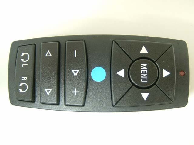
NHVWZU11
Jul 08, 2003Remote Control for the Vehicle
Equipment Class
DSC - Part 15 Security/Remote Control Transmitter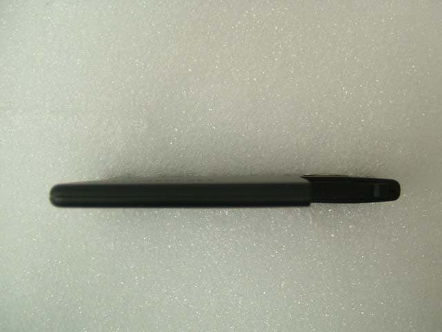
NHVWBU613
Jun 19, 2003Passive Entry System
Equipment Class
DSR - Part 15 Remote Control/Security Device Transceiver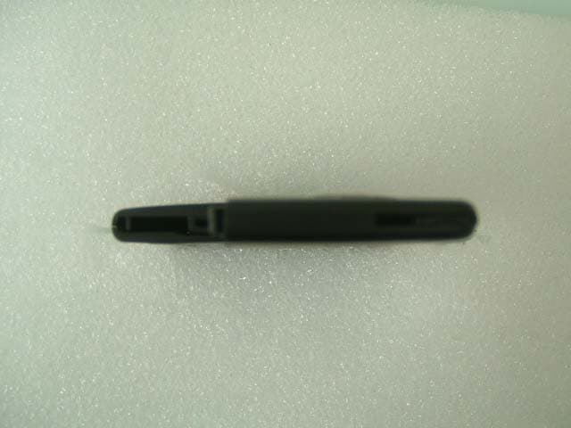
NHVWBU614
Jun 19, 2003Passive Entry System
Equipment Class
DSR - Part 15 Remote Control/Security Device Transceiver
NHVWDU614
Jun 16, 2003Passive Entry System
Equipment Class
DCD - Part 15 Low Power Transmitter Below 1705 kHz
NHVWDU613
Jun 11, 2003Passive Entry System
Equipment Class
DCD - Part 15 Low Power Transmitter Below 1705 kHz