NHVWDJ441Passive Entry System
Tohoku Alps Co Ltd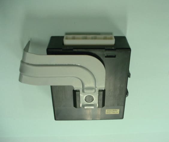
Click to zoom
Application Details
- Equipment Class
- DXX - Part 15 Low Power Communication Device Transmitter
- Date of Grant
- Feb 04, 2003
- Application Purpose
- Original Equipment
- Date of Application
- Feb 04, 2003
- Equipment Note
- Passive Entry System
- Frequency Range
- 0.12500000 - 0.12500000
- Company
- Tohoku Alps Co Ltd
- Country
- Japan
Documents & Files
Document Text
Text extracted from the exhibit documents filed with the FCC. Open a document above to read the original.
Users Manual
Document No. Title Page 5AX000XX00 Product Specification Background Passive Entry System FORMAT NO. FIRMWARE_A(VER 0.01) CONTENTS 1. PREFACE.................................................................................................................................4 2. PASSSIVE ACCSESS ENTRY FUNCTIONALITY.....................................................................5 2.1. Door Unlocking..............................................................................................................................................5 2.2. Engine Start...................................................................................................................................................6 2.3. Engine Stop....................................................................................................................................................6 2.4. Door Locking (Push switch)..........................................................................................................................7 3. ACTIVE ACCESS ENTRY FUNCTIONALITY............................................................................8 3.1. Door Unlocking..............................................................................................................................................8 3.2. Engine Start...................................................................................................................................................8 3.3. Engine Stop....................................................................................................................................................8 3.4. Door Locking..................................................................................................................................................8 4. ENTRY SYSTEM OPTIONS......................................................................................................9 4.1. System Schematic.........................................................................................................................................9 4.2. Modules..........................................................................................................................................................9 4.2.1. FOB ECU................................................................................................................................................9 4.2.2. Entry System ECU..................................................................................................................................9 5. SYSTEM CHARACTERISTICS...............................................................................................10 5.1. Antenna Areas.............................................................................................................................................10 5.2. Exciter Locations.........................................................................................................................................11 5.3. Switch Input Locations (Door handle, Touch sensor)................................................................................12 6. ELECTRICAL CHARACTERISTICS.......................................................................................13 6.1. FOB..............................................................................................................................................................13 6.2. Entry System ECU.......................................................................................................................................13 Document No. Title Page 5AX000XX00 Product Specification Background Passive Entry System FORMAT NO. FIRMWARE_A(VER 0.01) 1. Preface This document describes the requirements and operation of the Passive Entry System. However, this document is especially for the Entry system ECU (acronym for Electric Control Unit) and the FOB. The FOB consists the following functionality for passive access and active access: • Door unlocking / locking (however, only for request by means of switch operation) • Trunk unlocking / locking (however, only for request by means of switch operation) • LF decoding • RF encoding • Communication data encryption (cryptograph, anti-collision, rolling code and stuff) And the entry system ECU consists of the following functionality: • Door unlocking / locking • Trunk unlocking / locking • Engine start (/ stop) • LF encoding • RF encoding • Communication data encryption (cryptograph, anti-collision, rolling code and stuff) • LF antenna unit control • Communication with the node ECUs connected to the body bus (e.g. CAN, J1850, customer dependent bus) As a further function, both the FOB and the entry system ECU provides the following function: • Learning mode for programming the manufacturing data and stuff • Data locking and password protection • Diagnostic (based upon ISO9141 if required) Document No. Title Page 5AX000XX00 Product Specification Background Passive Entry System FORMAT NO. FIRMWARE_A(VER 0.01) 2. Passsive Accsess Entry Functionality A proximity sensor located on, for example the door handles, mirrors and trunk lid will be used for proximity check if user is in neighborhood of the vehicle. The switch input will trigger for unlocking and open the doors and trunk. Figure 1 2.1.Door Unlocking • User pull / touch the door handle (sensing of door handle switch). • ECU sends LF-challenge via exterior antenna. • FOB sends RF-response to the ECU. • Door unlocking status is engaged. • Doors are opened. Figure 2 Proximity sensor Switch input (door handle) LF RF FOB Document No. Title Page 5AX000XX00 Product Specification Background Passive Entry System FORMAT NO. FIRMWARE_A(VER 0.01) 2.2.Engine Start • User pushes / operate the engine start button / knob. • ECU sends LF-challenge via interior antenna. • FOB sends RF-response to the ECU. • Immobilizer ECU receives and authorize the response. • Engine controller ECU receives the author…
Text truncated - open the document above for the full version.
Cover Letter(s)
American Telecommunications Certification Body Inc. 6731 Whittier Ave, McLean, VA 22101 January 24, 2003 RE: FCC ID: NHVWDJ441 Attention: I have a few comments on this Application. 1. Please remove the shield covering the components in the upper left corner of the internal photo for the top of the board. Please provide photos of what is under this shield. 2. The manual would indicate that there are a number of antennas used with this device. The schematics are not sufficiently clear enough to determine the antenna useage for this device. Please confirm that there is only one transmit antenna and please identify this antenna. If the device does transmit on more than one antenna, please describe how it transmits on only one at a time. If the device transmits on more than one antenna at a time, please explain the measures you have taken during testing to insure that testing was performed with all antenna(s) transmitting at the same time and that the emissions from the system is not over the limit. If the latter is the case, please note that all 7 antennas must be used during testing and all five must be located in a typical arrangement. Dennis Ward mailto:[email protected] The items indicated above must be submitted before processing can continue on the above referenced application. Failure to provide the requested information may result in application termination. Correspondence should be considered part of the permanent submission and may be viewed from the Internet after a Grant of Equipment Authorization is issued. Please do not respond to this correspondence using the email reply button. In order for your response to be processed expeditiously, you must submit your documents through the AmericanTCB.com website. Also, please note that partial responses increase processing time and should not be submitted. Any questions about the content of this correspondence should be directed to the sender.
Cover Letter(s)
Subject: Re: NHVWDJ441 comments Date: Wed, 29 Jan 2003 17:59:18 +0900 From: [email protected] To: Dennis Ward <[email protected]> CC: [email protected] Dear Dennis, Thank you very much for your contact on the above application. I make a reply as follow: 1. Please see the file "Internal photo2". Page3 shows the circuit board under the shield. Is this aceptable? 2. Contents of Antenna is common among 7 antennas though their shapes are bit different. Each drive circuit of the C/U is basically connected to an independent antenna, respectively. Therefore, one drive circuit only drives one antenna. The communication procedure of the system is as follows; When a user wears a portable unit and pushes a switch (named as request switch) next to a door knob of an automobile with his hand, an LF antenna connected to the door knob transmits 125 kHz signals. Then, when the portable unit worn with the user receives the LF signals, the portable unit transmits RF signals with the ID code. The transmitted ID code is received by a tuner in a control unit installed in the automobile and confirms if the decoded code is identical to the registered code. If the code is identical, the closed door is opened or the opened door is closed. In addition the confirmation operation same as the door open is started, when the engine is activated by using an engine key. Furthermore, when the user locks the door from outside remaining his portable unit inside the automobile, this system operates not to make the door lock. Best regards, Yukie Koyama ::::::::::::::::::::::::::::: EMC Head Office Division A-Pex International Co.,Ltd. 4383-326 Asama-cho Ise-shi Mie-ken 516-0021 JAPAN TEL +81-596-24-8116 FAX +81-596-24-8124 E-mail:[email protected] ::::::::::::::::::::::::::::: --Original Message 2003/01/25 6:18:22-- Please see comments Thanks Dennis - 1-24-03 NHVWDJ441_ATCB Comments.pdf
Cover Letter(s)
Subject: Re: NHVWDJ441 comments Date: Tue, 4 Feb 2003 09:09:15 +0900 From: [email protected] To: Dennis Ward <[email protected]> CC: [email protected], [email protected] Hello Dennis, I reply to comment 2 with regard to FCC ID: NHVWDJ441 on Jan. 24 Entry system ECU has several LF Exciters. However, MCU drives only either one LF Exciter of them. The operation of the system is as follows; 1.When a user sends any command using the portable unit FOB to the entry system ECU from the several yards apart from the automobile, the user pushes any button on the portable unit FOB. Then the entry system ECU sends a inquiry message using the Interior LF Exciter to the FOB. Responding to this inquiry, the FOB sends the ID to the entry system ECU and then the MCU of the ECU drives the corresponding key $B!G (Bs open or close. 2.When the user, who wears the portable unit FOB, approaches in neighborhood of the automobile and touches it, a proximity sensor located on, for example the door handles and trunk lid senses the user $B!G (Bs action and sends a signal to the MCU. The MCU sends the LF-challenge to the FOB through the LF Exciter with antenna. The FOB sends RF-response to the ECU. If the ID is correct, the corresponding door opens or closes depending on the status by driven based on the MCU decision. Above functions are described in the "user manual" submitted. As described above, the entry system ECU drives only one LF Exciter with antenna. For the testing in accordance with FCC rules and ANSI C63.4, the entry system ECU with the interior LF Exciter, which is expected the highest radiated power, was measured and reported. Are the above answers acceptable? Thank you very much. Best regards, Yukie Koyama ::::::::::::::::::::::::::::: EMC Head Office Division A-Pex International Co.,Ltd. 4383-326 Asama-cho Ise-shi Mie-ken 516-0021 JAPAN TEL +81-596-24-8116 FAX +81-596-24-8124 E-mail:[email protected] ::::::::::::::::::::::::::::: --Original Message 2003/01/30 11:08:46-- Hi Yukie also, please note that in the explanation below you have not identified the antenna but only said there are 7 that are similar. What type antenna are these? Does the device transmit on more than one at a time. Please see the original comments item and answer the parts pertaining to this. Thanks Dennis [email protected] wrote: > Dear Dennis, > > Thank you very much for your contact on the above application. I make a > reply as follow: > > 1. Please see the file "Internal photo2". Page3 shows the circuit board > under the shield. Is this aceptable? > > 2. Contents of Antenna is common among 7 antennas though their shapes are > bit different. > > Each drive circuit of the C/U is basically connected to an independent > antenna, respectively. Therefore, one drive circuit only drives one > antenna. > The communication procedure of the system is as follows; > When a user wears a portable unit and pushes a switch (named as request > switch) next to a door knob of an automobile with his hand, an LF antenna > connected to the door knob transmits 125 kHz signals. Then, when the > portable unit worn with the user receives the LF signals, the portable unit > transmits RF signals with the ID code. The transmitted ID code is received > by a tuner in a control unit installed in the automobile and confirms if > the decoded code is identical to the registered code. If the code is > identical, the closed door is opened or the opened door is closed. > In addition the confirmation operation same as the door open is started, > when the engine is activated by using an engine key. Furthermore, when the > user locks the door from outside remaining his portable unit inside the > automobile, this system operates not to make the door lock. > > Best regards, > > Yukie Koyama > ::::::::::::::::::::::::::::: > EMC Head Office Division > A-Pex International Co.,Ltd. > 4383-326 Asama-cho Ise-shi > Mie-ken 516-0021 JAPAN > TEL +81-596-24-8116 > FAX +81-596-24-8124 > E-mail:[email protected] > ::::::::::::::::::::::::::::: > > --Original Message 2003/01/25 6:18:22-- > Please see comments > Thanks > Dennis > - 1-24-03 NHVWDJ441_ATCB Comments.pdf
External Photos
TOHOKU ALPS CO.,LTD Control Unit of Passive Entry System FCC ID: NHVWDJ441 <External photos> Front view TOHOKU ALPS CO.,LTD Control Unit of Passive Entry System FCC ID: NHVWDJ441 Rear view TOHOKU ALPS CO.,LTD Control Unit of Passive Entry System FCC ID: NHVWDJ441 Overview
ID Label/Location Info
ALPS ELECTRIC Co., LTD TFWD1J441 Label Label materials Surface material : PET (polyethylene terephthalate) Bonding material : Adhesive (PA-T1)
Internal Photos
TOHOKU ALPS CO.,LTD Control Unit of Passive Entry System FCC ID: NHVWDJ441 <Internal photos> Circuit board<front> TOHOKU ALPS CO.,LTD Control Unit of Passive Entry System FCC ID: NHVWDJ441 Circuit board<rear >
Internal Photos
TOHOKU ALPS CO.,LTD Control Unit of Passive Entry System FCC ID: NHVWDJ441 <Internal photos> Circuit board<front> TOHOKU ALPS CO.,LTD Control Unit of Passive Entry System FCC ID: NHVWDJ441 Circuit board<rear > TOHOKU ALPS CO.,LTD Control Unit of Passive Entry System FCC ID: NHVWDJ441
Internal Photos
TOHOKU ALPS CO.,LTD Control Unit of Passive Entry System FCC ID: NHVWDJ441 <Internal photos> Circuit board<front> TOHOKU ALPS CO.,LTD Control Unit of Passive Entry System FCC ID: NHVWDJ441 Circuit board<rear > TOHOKU ALPS CO.,LTD Control Unit of Passive Entry System FCC ID: NHVWDJ441 TOHOKU ALPS CO.,LTD Control Unit of Passive Entry System FCC ID: NHVWDJ441 TOHOKU ALPS CO.,LTD Control Unit of Passive Entry System FCC ID: NHVWDJ441
Operational Description
ALPS ELECTRIC Co., LTD 1.System block diagram Smart Keyless Unit B CAN Hi CAN Lo ACC B 5V B ECM BCM BACK DOOR BACK DOOR OPEN SW ASST Dr RR RL B CDL Dr UNLOCK OTHER UNLOCK CDL ACTR Dr door ANT Room Ant 1 As door ANT Back door ANT Ragtag Ant Dr Request SW Asst request SW Dr BUZZER 19 Room Ant 3 Room Ant 2 IGN SW USM MATER STRG LOCK UNIT SIG B B B IMMOB ANT 20 35 36 33 34 14 13 16 15 18 17 38 37 GND KEY SW PUSH SW 11 6 10 3 2 7 27 40 4 23 24 12 29 25 5 28 26 Dr State SW Back door Request SW 28 P Position SW 1 32 3 ALPS ELECTRIC Co., LTD 2. C onnector & Term inal N o . Term inal N o .T e rm inal N a m e T e rm inal N o .T e rm inal N a m e 1 STRG LOCK 5V OUTPUT 21 DONGLE K-LINE 2 C A N H i 2 2 K E Y L O C K S O L fo r M T 3 C A N L o 2 3 (B A C K D O O R O P E N O U T P U T O P T ) 4 Dr BUZZER OUTPUT 24 (BACK DOOR OPEN SW OPT) 5 D r request SW 25 ASST request SW 6IG N S W 2 6 (S T O P L A M P S W O P T ) 7 KEY SW 27 PUSH SW 8Immobilizer ANT SIG IN 28 (Dr LOCK STATE SW OPT) 9Immobilizer ANT SIG O UT 29 BAC K D O O R request SW 10 ACC SW 30 SECURIT Y IND 11 BAT 31 STRG LOCK UNIT GND 12 GND 32 STRG LOCK UNIT SIG 13 LUGGAGE ANT + 33 (ROOM ANT2+ OPT) 14 LUGGAGE ANT - 34 (ROOM ANT2- OPT) 15 RO O M ANT1+ 35 (RO O M ANT3+ O PT) 16 RO O M ANT1- 36 (RO O M ANT3- O PT) 17 BACK DOOR ANT+ 37 ASST DOOR ANT+ 18 BACK DOOR ANT- 38 ASST DOOR ANT- 1 9 D r D O O R A N T + 3 9 (P R a n g e S W O P T ) 20 Dr DOOR ANT- 40 ASST SELECT UNLOCK OUTPUT 3. C A S E SIZE 21 3 4 5 6 7 8 9 10 11 12 13 14 15 16 17 18 19 20 2221 23 24 25 26 27 28 29 30 31 32 33 34 35 36 37 38 39 40 TH40HW 32m m max3mm max3mm 80m m 100m m connector ALPS ELECTRIC Co., LTD 4.Function i-key unit has 3 state of door lock state,"lock state"or"ready to all door unlock"or"unlock state" for Each door independently Each door's door lock state is defined following state chart *1 W hen i-key unit re ce ived can com m and"dr door actr info"="10" or "other door actr info"="10" from BCM , I-key unit re co gn iz e B C M m a k e s a ll d o o rs lock *2 W hen I-key unit received can com m and"other door actr info"="01" from BC M , I-key unit re co gniz e B C M m a k e s a ll d o o rs u n lock (2 )O p e ra tion by request SW door lock state*3 O utput when the request SW is operated lock state operated door's select unlock output ready to all door unlock all door unlock output unlock state lock output *3 "door lo c k s ta te " o f w h ich that request SW operated 1-2.Operation by request SW (W hen the custom er setting state is "SELECTIVE UNLO CK"="1") (1 )D o o r lock state of each door i-key unit has 2 state of door lock state,"lock state"or"unlo c k " fo r a ll d o o r door lock state is defined following state ch art *1 W hen i-key unit re ce ived can com m and"dr door actr info"="10" or "other door actr info"="10" from BCM , I-key unit re co gn iz e B C M m a k e s a ll d o o rs lock *2 W hen I-key unit received can com m and"other door actr info"="01" from BC M , I-key recognize B C M m akes all d o o rs u n lock (2 )O p e ra tion by request SW door lock state O utput when the request SW is operated lock state all door unlock output unlock state lock output Dr Door lock state ready to all d o o r unlock unlo c k state ・start to Dr door select unlock operation by "operation of the unlock button of I-key"or "operation of the Dr request sw " ・BCM makes all d o o rs lock *1 ・B C M m akes all doors unlock *2 (e x c e p t A S S T d o o r s e lect u n lock output) ・after 5sec from the D r door's d o o r lock state becam e "ready to a ll d o o r u n lo c k " fro m " lock state" ・Dr door close → open ・BCM makes all d o o rs u n lock *2 ・Any door whic h d o o r lock state is "lock state" close →open ・RR door or RL door close → open ・BCM makes all d o o rs lock *1 Asst Door lock state ready to all door unlock unlock state ・start to Asst door select unlock operation by "operation o f th e A s s t re q u e s t s w " ・BCM makes all d o o rs lock *1 ・B C M m akes all doors unlock *2 ・after 5sec from the Asst door's d o o r lock state becam e "ready to a ll d o o r u n lo c k " fro m " lock state" ・Asst door close → open ・BCM makes all d o o rs u n lock *2 ・Any door which door lock state is "lock state" close →open ・RR door or RL door close → open ・BCM makes all d o o rs lock *1 Back Door lock state ready to all door unlock unlock state ・start to Back door select unlock operation by "operation of the back request sw" ・BCM makes all d o o rs lock *1 ・B C M m akes all doors unlock *2 (e x c e p t A S S T d o o r s e lect u n lock output) ・after 5sec from the Back door's d o o r lock state becam e "ready to a ll d o o r u n lo c k " fro m " lock state" ・Back door close → open ・BCM makes all d o o rs u n lock *2 ・Any door which door lock state is "lock state" close →open ・RR door or RL door close → open ・BCM makes all d o o rs lock *1 lock state unlock state ・B C M m akes all d o o rs u n lock *2 ・Any door close →open w hen door lock state is "lock state" ・BCM makes all d o o rs lock *1 ALPS ELECTRIC Co., LTD 1-3.Operation by i- k e y b a d g e b u tto n (When the custom er settin g state is "SELEC TIVE UNLO C K"="0") (1 )O p e ra tion by I-key badge button operated button Dr's door lock state output lock button -lock outpu t unlo c k bu tto n first lock state Dr door select unlock output ready to all door unlock all door unlock output unlock state Dr door select unlock output second -all door unlock output (2 )J u d g e m e n t c o n d itio n first tim e o r s e c o n d time operatio n o f u n lock button of I-key badge I-key badge com m and times state defin e d fo llowin g s ta te c h a rt ready to receive first time unlock com m and:when I-key unit re c e ived unlo c k c o m m a n d fro m I- k e y b a d g e d u ring this stat e I-key unit ju d g e first time unlock com m and ready to receive second time unlock com m and:when I-key unit re c e ived unlock com m and from I- k e y b a d g e d u ring this s t I-key unit judge second times unlock com m and *1 W hen i-key unit …
Text truncated - open the document above for the full version.
Test Setup Photos
Test report No. : 23EE0005-HO-2 Page : 11 of 16 FCC ID : NHVWDJ441 Issued date : January 22, 2003 A-Pex International Co., Ltd. EMC Head Office Division. 4383-326 Asama-cho, Ise-shi, Mie-ken 516-0021 JAPAN Telephone : +81 596 24 8116 Facsimile : +81 596 24 8124 APPENDIX 1: Photographs of test setup Radiated emission
Contact Information
Applicant
Tom Takata
81 229 233111Fax: 81 229 229997
Technical Contact
A-Pex International Co., Ltd.Yoshiyuki Iwasa
[email protected]81-596-24-8116
4383-326 Asama-cho, · Ise-shi, Mie-ken · Japan
Test Firm
UL Apex Co., Ltd.Tetsuya Hashimoto
Technical Specifications
| # | Rule Parts | Frequency Range | Power Output |
|---|---|---|---|
| 1 | 15C | 0.125 MHz - 0.125 MHz | - |
Other Applications from Tohoku Alps Co Ltd
NHVWZU11
Jul 08, 2003Remote Control for the Vehicle
Equipment Class
DSC - Part 15 Security/Remote Control Transmitter
NHVWBU613
Jun 19, 2003Passive Entry System
Equipment Class
DSR - Part 15 Remote Control/Security Device Transceiver
NHVWBU614
Jun 19, 2003Passive Entry System
Equipment Class
DSR - Part 15 Remote Control/Security Device Transceiver
NHVWDU614
Jun 16, 2003Passive Entry System
Equipment Class
DCD - Part 15 Low Power Transmitter Below 1705 kHz
NHVWDU613
Jun 11, 2003Passive Entry System
Equipment Class
DCD - Part 15 Low Power Transmitter Below 1705 kHz