NJIAL200AssetLink 200
CSI Wireless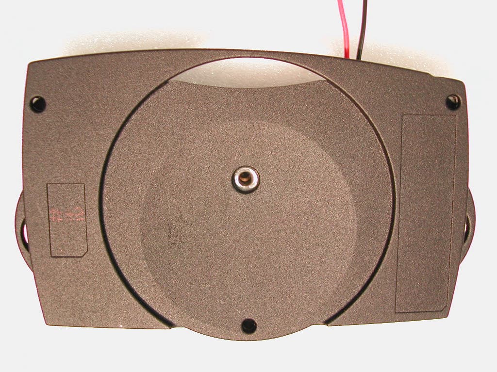
Click to zoom
Application Details
- Equipment Class
- TNB - Licensed Non-Broadcast Station Transmitter
- Date of Grant
- Jan 27, 2002
- Application Purpose
- Original Equipment
- Date of Application
- Jan 27, 2002
- Equipment Note
- AssetLink 200
- Frequency Range
- 824.04000000 - 848.97000000
- Company
- CSI Wireless
- Country
- United States
Documents & Files
Document Text
Text extracted from the exhibit documents filed with the FCC. Open a document above to read the original.
Users Manual
NJIAL200 EXHIBIT 7 “Users Manual” This exhibit is submitted to comply in part with FCC 47CFR section 2.1033 part b item 3: “ A copy of the installation and operating instructions to be furnished the user. A draft copy of the instructions may be submitted if the actual document is not available. The actual document shall be furnished when it becomes available.” This exhibit is submitted to comply with FCC 47CFR section 2.1033 part c item 3: “A copy of the installation and operating instruction to be furnished the user. A draft copy of the instructions may be submitted if the actual document is not available. The actual document shall be furnished to the FCC when it becomes available.” Submission examination in detail on FCC 47CFR section 2.1033 part b item 3: Whereas the “Installation and Operating Instructions” is shown below, and the reference in section 2.1033 for the same document is the “installation and operation instructions”, and the Form 731 equivalent reference is the “User Manual”, the “Installation and Operating Instructions” document is used as a submission for this requirement and is evidenced. Submission examination on FCC 47CFR section 2.1033 part c item 3: Whereas the “Installation and Operating Instructions” is shown below, and the reference in section 2.1033 for the same document is the “installation and operation instructions”, and the Form 731 equivalent reference is the “User Manual”, the “Installation and Operating Instructions” document is used as a submission for this requirement and is evidenced. CSI-Wireless AssetLink 200 Installation and Operating Instructions Revision 1.0 Page 1 1/2/2002 CSI-Wireless Wireless-Link AssetLink 200 Installation and Operating Instructions CSI-Wireless AssetLink 200 Installation and Operating Instructions Revision 1.0 Page 2 1/2/2002 Document: AssetLink 200 Installation and Operating Instructions Date: January 2, 2002 Issue: Rev. 1.0 Author: Russ Braathen copyright 2001 CSI-Wireless Inc. TABLE OF CONTENTS DEFINITIONS...............................................................................................................................3 1 INTRODUCTION..................................................................................................................4 1.1 OPERATIONAL OVERVIEW...............................................................................................4 1.2 OPERATING MODES..........................................................................................................4 2 ASSETLINK 200 INTERNAL COMPONENTS................................................................4 2.1 TWELVE CHANNEL GPS RECEIVER.................................................................................4 2.1.1 GPS Position/Velocity Fix.......................................................................................4 2.1.2 Geo-fences................................................................................................................5 2.1.3 Distance and Home Origin......................................................................................5 2.2 SYSTEM TIMING...............................................................................................................5 2.3 EXTERNAL I/O..................................................................................................................6 2.4 EVENT MONITOR AND EXCEPTION HANDLER.................................................................6 2.5 ON BOARD DIAGNOSTICS................................................................................................6 2.6 POWER CONSUMPTION PROFILE......................................................................................7 3 PERFORMANCE SPECIFICATIONS...............................................................................7 3.1 CELLULAR TRANSCEIVER................................................................................................7 3.2 GPS RECEIVER.................................................................................................................7 3.3 ASSETLINK 200 ANTENNA SPECIFICATIONS....................................................................8 3.3.1 Warning on use of cellular antennas.....................................................8 3.3.2 Cellular Antenna Specifications...............................................................................8 3.3.3 GPS Antenna Specifications.....................................................................................8 3.4 ENVIRONMENTAL REQUIREMENTS..................................................................................9 3.4.1 Temperature and Humidity......................................................................................9 3.4.2 Vibration..................................................................................................................9 3.5 I/O LINES........................................................................................................................9 3.5.1 Serial Data Port.......................................................................................................9 3.5.2 Analogue & Digital I/O Lines..................................................................................9 3.5.3 External Connector Pin Assignments.....................................................................10 3.5.4 Power Lead Assignments.......................................................................................10 4 MECHANICAL AND PHYSICAL....................................................................................11 4.1 HOUSING........................................................................................................................11 CSI-Wireless AssetLink 200 Installation and Operating Instructions Revision 1.0 Page 3 1/2/2002 Acronyms and Abbreviations bps Bits per Second AMPS American Mobile Phone System Cellular Section Cellular Data Modem for AMPS DAC Digital to Analog Converter DGPS Differential …
Text truncated - open the document above for the full version.
Attestation Statements
NJIAL200 EXHIBIT 10 “Attestation Statement” This exhibit is submitted to comply in part with FCC 47CFR section 22.919 part c: “The ESN must be factory set and must not be alterable, transferable, removable or otherwise able to be manipulated. Cellular mobile equipment must be designed such that any attempt to remove, tamper with, or change the ESN chip, its logic system, or firmware originally programmed by the manufacturer will render the mobile transmitter inoperative.” Submission examination in detail on FCC 47CFR section 22.919 part c: Whereas the ESN Attestation statement of compliance is shown below, this requirement is evidenced. CSI Wireless™ Wireless Link Corporation NJIAL200 Statement of Compliance with Electrical Serial Number (ESN) Regulations The Electrical Serial Number (ESN) is encrypted and stored in a non-volatile memory location in the NJIAL200. A non encrypted version of the ESN is stored in a separate location in the memory. Upon power up the software decrypts the encrypted ESN, using a key known only to Wireless Link, and compares it to the non-encrypted version of ESN. If they do not match, the cellular section will not operate or attempt to register on the cellular network. The ESN is set only by Wireless Link factory and cannot otherwise be altered, transferred or removed. Any attempts to manipulate the ESN will render the phone inoperative.
Cover Letter(s)
CSI- Wireless Suite 260 6815 8th St. N.E. Calgary, Alberta Canada c-" T2E 7H7 Jan 4, 2002 Telecommunication Certification Body Intertek Testing Services 1365 Adams Court Melno Court, CA 94025 USA Sirs: CSI- Wireless gives Intertek the authority to submit Reference AL-020-00040, Model AL200 to the F.C.C. in the U.S.A. for approval under FCC Part 15 and FCC Part 22 as NJIAL200. This product is referred to as the " AssetLink 200" for marketing purposes. For CSI-Wireless, '-j ?- ~ Walter reller, Vice President R&D.
External Photos
NJIAL200 EXHIBIT 2 “External Photos” This exhibit is submitted to comply in part with FCC 47CFR section 2.1033 part b item 7: “ A sufficient number of photographs to clearly show the exterior appearance, the construction, the component placement on the chassis, and the chassis assembly. The exterior views shall show the overall appearance, the antenna used with the device (if any), the controls available to the user, and the required identification label in sufficient detail so that the name and FCC identifier can be read. In lieu of a photograph of the label, a sample label (or facsimile thereof) may be submitted together with a sketch showing where this label will be placed on the equipment. Photographs shall be of size A4 (21 cm x 29.7 cm) or 8 x 10 inches (20.2 cm x 25.4 cm) paper. A sample label or facsimile together with the sketch showing the placement of this label shall be on the same size paper.” This exhibit is submitted to comply in part with FCC 47CFR section 2.1033 part c item 12: “Photographs (8” x 10”) of the equipment of sufficient clarity to reveal equipment construction and layout, including meters, if any, and labels for controls and meters and sufficient views of the internal construction to define component placement and chassis assembly. Insofar as these requirements are met by photographs or drawings contained in instruction manuals supplied with the certification request, additional photographs are necessary only to complete the required showing.” Submission examination in detail on FCC 47CFR section 2.1033 part b item 7: Whereas the photographs show all faces of the applied for device, there are sufficient photographs supplied to show external appearance. Whereas the photographs supplied are in PDF format, the size constraint can be met by printing to the appropriate size. Whereas the antenna is to be connected to the device by two connectors, the connectors are shown. The typical antennas used are shown attached the photographs in the test report, which is in Exhibit 5 “Test Report”. Whereas there are no controls and meters on the device or attached to the device when in normal use, none are shown in the photographs. Whereas Exhibit 1 “ID Label/Location Info” clearly shows both the labels and the label placement, the label requirement is evidenced in Exhibit 1. Submission examination in detail on FCC 47CFR section 2.1033 part c item 12: Whereas the photographs supplied are in PDF format, the size constraint can be met by printing to the appropriate size. Whereas the photographs show all faces of the applied for device, the equipment construction and layout is clearly shown. Whereas there are no controls and meters on the device or attached to the device when in normal use, none are shown in the photographs. Whereas the Exhibit 8 “Internal Photos” contains internal photographs of the device, the internal construction to define component placement and chassis assembly is evidenced. Whereas the instruction manuals do not contain photographs, the Exhibit 7 “User’s Manual” is not used as evidence in this part of the submission. NJIAL200 bottom outside view NJIAL200 top outside view
ID Label/Location Info
NJIAL200 EXHIBIT 1 “ID Label/Location Info” This exhibit is submitted to comply with FCC 47CFR section 2.1033 part b item 1: “The full name and mailing address of the manufacturer of the device and the applicant for certification” This exhibit is submitted to comply with FCC 47CFR section 2.1033 part b item 2: “FCC Identifier” This exhibit is submitted to comply in part with FCC 47CFR section 2.1033 part b item 7: “ A sufficient number of photographs to clearly show the exterior appearance, the construction, the component placement on the chassis, and the chassis assembly. The exterior views shall show the overall appearance, the antenna used with the device (if any), the controls available to the user, and the required identification label in sufficient detail so that the name and FCC identifier can be read. In lieu of a photograph of the label, a sample label (or facsimile thereof) may be submitted together with a sketch showing where this label will be placed on the equipment. Photographs shall be of size A4 (21 cm x 29.7 cm) or 8 x 10 inches (20.2 cm x 25.4 cm) paper. A sample label or facsimile together with the sketch showing the placement of this label shall be on the same size paper.” This exhibit is submitted to comply with FCC 47CFR section 2.1033 part c item 1: “The full name and mailing address of the manufacturer of the device and the applicant for certification.” This exhibit is submitted to comply with FCC 47CFR section 2.1033 part c item 2: “FCC Identifier.” This exhibit is submitted to comply with FCC 47CFR section 2.1033 part c item 11: “A photograph or drawing of the equipment identification plate or label showing the information to be placed thereon.” Submission examination in detail on FCC 47CFR section 2.1033 part b item 1: Whereas the full name and address of both the manufacturer and the applicant are shown below, the requirement is evidenced. Submission examination in detail on FCC 47CFR section 2.1033 part b item 2: Whereas the drawing for the label is shown below, along with the ESN numbering label and the location of both labels is shown below the requirement is evidenced. Submission examination in detail on FCC 47CFR section 2.1033 part b item 7: Whereas this submission clearly shows both the labels and the label placement, the label requirements is evidenced. Whereas the photographs supplied are in PDF format, the size constraint can be met by printing to the appropriate size. Submission examination in detail on FCC 47CFR section 2.1033 part c item 1: Whereas the full name and mailing address of the manufacturer of the device and the applicant for certification is shown below, the requirement is evidenced. Submission examination in detail on FCC 47CFR section 2.1033 part c item 2: Whereas the drawing for the label is shown below, and the label contains the FCC identifier, the requirement is evidenced. Wheras the FCC Emissions Designators derivation is shown below, the requirement is evidenced. Submission examination in detail on FCC 47CFR section 2.1033 part c item 11: Whereas the drawing for the label is shown below, along with the ESN numbering label and the location of both labels is shown below the requirement is evidenced. NJIAL200 FCC 47CFR section 2.1033 part b item 1: Manufacturer of Device: CSI Wireless Incorporated 4110 9 th St. S.E. Calgary, Alberta, Canada T2G 3C4 Applicant for Certification: Russell Braathen CSI Wireless Incorporated 4110 9 th St. S.E. Calgary, Alberta, Canada T2G 3C4 NJIAL200 FCC 47CFR section 2.1033 part b item 2: The prefix allocated by the FCC to Wireless Link Inc. is NJI. Wireless Link Inc. is a fully owned subsidiary of CSI Wireless Inc., and the FCC prefix applies. The device is marketed under the name “AssetLink 200”, and the device nomenclature for the FCC application is: AL200 The FCC identifier is: NJIAL200 Title: Label, Model No / Regulatory Compliance, AssetLink (200) Calgary Alberta Canada Document No. 080-00042 Sheet 1 of 3 Rev. X3 Label, Model No / Regulatory Compliance, AssetLink (200) 080-00042 THIS DOCUMENT IS THE PROPERTY OF CSI WIRELESS, CALGARY, ALBERTA, CANADA. IT SHALL NOT BE USED FOR ANY PURPOSE EXCEPT THE MANUFACTURE OF ARTICLES FOR CSI WIRELESS WITHOUT WRITTEN PERMISSION OF CSI WIRELESS. Title: Label, Model No / Regulatory Compliance, AssetLink (200) Calgary Alberta Canada Document No. 080-00042 Sheet 2 of 3 Rev. X3 Originator: Peter Hill Revision History Rev EC No. Date Comments X1 01/08/15 Initial Release X2 01/08/16 “FCC No” changed to “FCC ID” X3 01/11/16 Part Number updated • Ref Number: typeface shall be 9 point Arial Bold, Black lettering. • FCC NO: typeface shall be 10 point Arial Bold, Black lettering. • FCC warning: typeface shall be 6 point Arial, Black lettering. • Canadian DoC number: typeface shall be 9 point Arial Bold, Black lettering. • Country of Origin: typeface shall be 8 point Arial Bold, Black lettering. Country of Origin to be supplied with each order. For example: “Made in USA” Note: The Canadian DoC number is to be added to the bottom left of the label when available. Ref No: LC-020-00040 FCC ID: NJIAL200 This device complies with Part 15 of the FCC Rules. Operation is subject to the following two conditions: (1) This device may not cause harmful interference, and (2) This device must accept any interference received, including interference that may cause undesired operation. DoC Number Made in “Country of Origin” 0.73” 2.73” 0.08” 0.08” All Dims tolerance +/- 0.005” Title: Label, Model No / Regulatory Compliance, AssetLink (200) Calgary Alberta Canada Document No. 080-00042 Sheet 3 of 3 Rev. X3 Label Material and Adhesive: Material: 0.002” METALLIZED SILVER (CHROME) POLYESTER (MYLAR) FILM Lamination: 0.001” TRANSPARENT MATTE MYLAR Ink Color: BLACK (INDELIBLE) Printed edge: None Adhesive: PERMANENT PRESSURE SENSITIVE W/ NOTE 1 REQUIREMENT (good tack and adhesion to smooth and rough metal and plastic surfaces.) Supplied with removable adhesive covering. NOTE 1: All material must…
Text truncated - open the document above for the full version.
Internal Photos
NJIAL200 EXHIBIT 8 “Internal Photos” This exhibit is submitted to comply in part with FCC 47CFR section 2.1033 part b item 7: “ A sufficient number of photographs to clearly show the exterior appearance, the construction, the component placement on the chassis, and the chassis assembly. The exterior views shall show the overall appearance, the antenna used with the device (if any), the controls available to the user, and the required identification label in sufficient detail so that the name and FCC identifier can be read. In lieu of a photograph of the label, a sample label (or facsimile thereof) may be submitted together with a sketch showing where this label will be placed on the equipment. Photographs shall be of size A4 (21 cm x 29.7 cm) or 8 x 10 inches (20.2 cm x 25.4 cm) paper. A sample label or facsimile together with the sketch showing the placement of this label shall be on the same size paper.” This exhibit is submitted to comply in part with FCC 47CFR section 2.1033 part c item 12: “Photographs (8” x 10”) of the equipment of sufficient clarity to reveal equipment construction and layout, including meters, if any, and labels for controls and meters and sufficient views of the internal construction to define component placement and chassis assembly. Insofar as these requirements are met by photographs or drawings contained in instruction manuals supplied with the certification request, additional photographs are necessary only to complete the required showing.” Submission examination in detail on FCC 47CFR section 2.1033 part b item 7: Whereas Exhibit 3 “External Photographs” contain the exterior appearance, the requirement is evidenced. Whereas the photographs clearly show the construction, the component placement on the chassis and the chassis assembly the requirement is evidenced. Whereas the photographs supplied are in PDF format, the size constraint can be met by printing to the appropriate size. Whereas there are no controls and meters on the device or attached to the device when in normal use, none are shown in the photographs. Whereas Exhibit 1 “ID Label/Location Info” clearly shows both the labels and the label placement, the label requirement is evidenced in Exhibit 1. Submission examination on FCC 47CFR section 2.1033 part c item 12: Whereas the photographs supplied are in PDF format, the size constraint can be met by printing to the appropriate size. Whereas the photographs show all construction details and component placement, the internal construction to define component placement and chassis assembly is evidenced. Whereas there are no controls and meters on the device or attached to the device when in normal use, none are shown in the photographs. Whereas the Exhibit 2 “External Photos” contains external photographs of the device, the external photograph requirement is evidenced. Whereas the instruction manuals do not contain photographs, the Exhibit 7 “User’s Manual” is not used as evidence in this part of the submission. NJIAL200 CCA top view NJIAL200 CCA bottom view NJIAL200 case top, inside view NJIAL200 case bottom, inside view
Operational Description
NJIAL200 EXHIBIT 9 “Operational Description” This exhibit is submitted to comply in part with FCC 47CFR section 2.1033 part b item 4: “ A brief description of the circuit functions of the device along with a statement describing how the device operates. This statement should contain a description of the ground system and antenna, if any, used with the device.” This exhibit is submitted to comply in part with FCC 47CFR section 2.1033 part b item 8: “If the equipment for which certification is being sought must be tested with peripheral or accessory devices connected or installed, a brief description of those peripherals or accessories. The peripheral or accessory devices shall be unmodified, commercially available equipment.” This exhibit is submitted to comply with FCC 47CFR section 2.1033 part c item 5: “Frequency Range.” This exhibit is submitted to comply with FCC 47CFR section 2.1033 part c item 6: “Range of operating power values or specific operating power levels, and description of any means provided for variation of operating power.” This exhibit is submitted to comply with FCC 47CFR section 2.1033 part c item 7: “Maximum power rating as defined in the applicable part(s) of the rules.” This exhibit is submitted to comply with FCC 47CFR section 2.1033 part c item 8: “The dc voltages applied to and dc currents into the final radio frequency amplifying device for normal operation over the power range.” This exhibit is submitted to in part comply with FCC 47CFR section 2.1033 part c item 10: “A schematic diagram and a description of all circuitry and devices provided for determining and stabilizing frequency, for suppression of spurious radiation, for limiting modulation, and for limiting power.” This exhibit is submitted to comply with FCC 47CFR section 2.1033 part c item 13: “For equipment employing digital modulation techniques, a detailed description of the modulation system to be used. Including the response characteristics (frequency, phase, amplitude) of any filters provided, and a description of the modulating wavetrain, shall be submitted for the maximum rated conditions under which the equipment will be operated.” This exhibit is submitted to comply with FCC 47CFR section 22.921: E911 call processing legislation. Submission examination in detail on FCC 47CFR section 2.1033 part b item 4: Whereas the description of the circuit functions is shown below, along with a statement of how the device operates this requirement is evidenced. Whereas the description of the ground system and reference to the antenna requirements in Exhibit 7 “Users Manual” is shown below this requirement is evidenced. Submission examination in detail on FCC 47CFR section 2.1033 part b item 8: Whereas the description of the peripheral or accessory devices is shown below, this requirement is evidenced. Wheras Exhibit 5 “Test Report” includes a listing of these devices, and photographs of the peripheral or accessory devices connected, this requirement is verified. Wheras Exhibit 6 “Test setup photos” shows photographs of the peripheral or accessory devices connected, this requirement is verified. Submission examination on FCC 47CFR section 2.1033 part c item 5: Whereas the frequency range of the device is shown, the requirement is evidenced. Submission examination on FCC 47CFR section 2.1033 part c item 6: Whereas the range of operating power values and specific operating levels along with a description of the means provided of variation of operating power is shown below, this requirement is evidenced. Submission examination on FCC 47CFR section 2.1033 part c item 7: Whereas the maximum power rating is shown below, and the applicable parts of the rules are quoted, this requirement is evidenced. Submission examination on FCC 47CFR section 2.1033 part c item 8: Whereas the dc voltage applied to and the dc currents for normal operation are described below this requirement is evidenced. Submission examination on FCC 47CFR section 2.1033 part c item 10: Whereas the schematics are shown in Exhibit 4 “Schematic Diagram” this requirement is evidenced. Whereas the device descriptions are shown in Exhibit 11 “Parts List/Tune Up Info” this requirement is evidenced. Whereas the circuitry description is shown below for suppression of spurious radiation, for limiting modulation and for limiting power, this requirement is evidenced. Whereas the adjustment of the device to meet the requirements is shown in Exhibit 11 “Parts List/Tune Up Info” this requirement is evidenced. Submission examination on FCC 47CFR section 2.1033 part c item 13: Whereas the description the digital modulation techniques is shown below, this requirement is evidenced. Submission examination on FCC 47CFR section 22.921: Whereas the device is shown to not allow user initiated calls as shown below, this requirement is evidenced. NJIAL200 FCC 47CFR section 2.1033 part b item 4: A brief description of the circuit functions of the NJIAL200 along with a statement describing how the NJIAL200 operates. This contains a description of the ground system and antenna used with the device. NJIAL200 AssetLink 200 Brief description of circuit functions of the device along with a statement describing how the device operates. Document: NJIAL200 Assetink Brief Description of Circuit Functions. Date: January 02, 2002 Issue: Rev 1 Authors: R. Braathen Company: CSI-Wireless NJIAL200 AssetLink Brief Description of Circuit Functions 2 of 7 TABLE OF CONTENTS Acronyms and Abbreviations.........................................................3 Introduction......................................................................................4 Operating Modes...............................................................................4 Operational Description..................................................................4 Function Control Processor..................................................................4 Twelve Channel GPS Receiver................................…
Text truncated - open the document above for the full version.
Operational Description
NJIAL200 EXHIBIT 13 “Operational Description” for “Emissions Designators” This exhibit is submitted to comply with the submission requirements of the FCC 47 CFR section 2.201: “The following system of designating emission, modulation and transmission characteristics shall be employed.....” Submission examination in detail on FCC 47CFR section 2.201: Whereas the “Emissions Designations” as shown below conforms to the cellular telephone emissions designations, and is also shown to be correct by reference to section 2.201, the requirement is evidenced. FCC Emissions Designators for NJIAL200 Page 1 of 3 FCC Emissions Designators for AssetLink 200 (NJIAL200) R. Braathen Dec 13, 2001 The designators applied for in the FCC application for AssetLink 200 (NJIAL200)) are: 40K0F1D 40K0F8W Per instruction (g) of 47CFR2.201, the necessary bandwidth is to be included before these designators for the full designation. Per instructions (a) through (f) of 47CFR2.201 the first, second and third symbols are included. The two types cellular communications channels are used, they are denoted Control Channel and Communications Channel and each is examined in detail on pages 2 and 3. FCC Emissions Designators for NJIAL200 Page 2 of 3 Control Channel: Necessary bandwidth is +/-20 KHz, which has the symbol: 40K0 Symbol Number Symbol Requirement Choice Designator First type of modulation of the carrier Frequency Modulation F Second nature of signals modulating the carrier A single channel containing quantized or digital information without the use of a modulating sub-carrier, excluding time-division multiplex 1 Third Type of information to be transmitted Data transmission, telemetry, telecommand D Designator for Control Channel: 40K0F1D FCC Emissions Designators for NJIAL200 Page 3 of 3 Communications Channel: The Communications Channel uses Handoff Commands Communicatons which are telecommand at +/-20 KHz bandwidth and also Analogue Communications with FM modulation within 15 KHz bandwidth. Handoff Command Communications: Necessary bandwidth is +/-20 KHz, which has the symbol: 40K0 Symbol Number Symbol Requirement Choice Designator First type of modulation of the carrier Frequency Modulation F Second nature of signals modulating the carrier A single channel containing quantized or digital information without the use of a modulating sub-carrier 1 Third Type of information to be transmitted Data transmission, telemetry, telecommand D Analogue Communications: Bandwidth necessary is 15 KHz, the wider bandwidth needed of the Handoff Commands overrides this for the symbol: 40K0 The signals being sent in this mode are the SAT (Supervisory Audio Tone) and Voice/Modem/DTMF. The SAT is an analogue signaling tone at either 5970, 6000 or 6030 Hz using a +/- 2 KHz Peak Frequency Modulation. The Voice/Modem/DTMF modulations are analog signals band limited from 300 Hz to 3 Khz and with a maximum deviation of less than +/-12 KHz Peak Frequency Modulation. Symbol Number Symbol Requirement Choice Designator First type of modulation of the carrier Frequency Modulation F Second nature of signals modulating the carrier Two or more channels containing analogue information 8 Third Type of information to be transmitted Telephony (E) and Telemetry (D) for a combination (W) W Handoff Commands Communications modulation designator is F1D plus the Analogue Communications modulation designator is F8W to give the following: F: as both modes are frequency modulation 8: which is a combination of nature of signals for both modes, 1 and 8 are then a “Composite system with one or more channels containing quantized or digital information, together with one or more channels containing analogue information.” W: this is a combination of the D and W designators. Designator for Communications Channel: 40K0F8W
RF Exposure Info
NJIAL200 E…
Text truncated - open the document above for the full version.
Contact Information
Applicant
Eric Maxon(Program Director)
Technical Contact
CSI Wireless Inc.Russell E Braathen
[email protected]403-640-6720
4110 9th Street S.E · Calgary, Alberta · Canada
Non-Technical Contact
CSI Wireless Inc.Michael R Znack
[email protected]403-640-6720
Test Firm
MPB Technologies Inc.Daniele Zanette
Technical Specifications
| # | Rule Parts | Frequency Range | Power Output | Emission | Tolerance |
|---|---|---|---|---|---|
| 2 | 22H | 824.04 MHz - 848.97 MHz | 750.00 mW | 40K0F1D | 2.5 ppm |
Other Applications from CSI Wireless
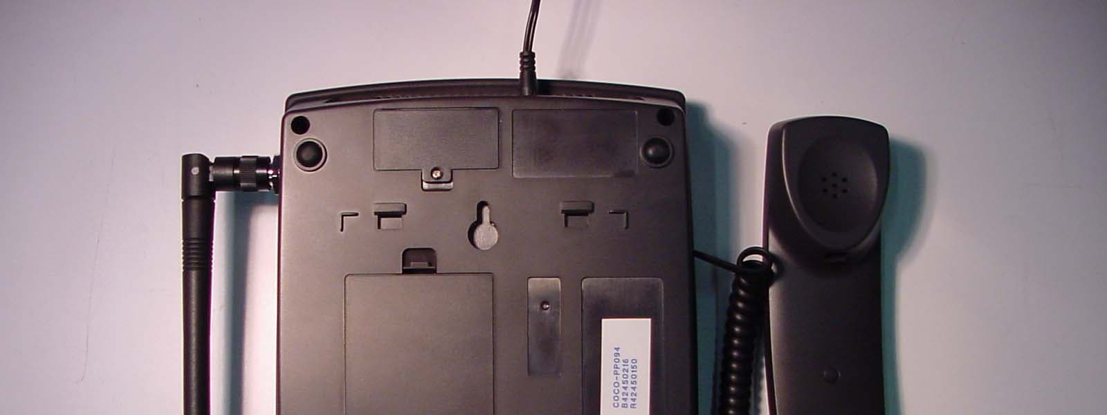
NJIFW1900
Nov 14, 2004GSM Fixed Wireless Phone
Equipment Class
PCB - PCS Licensed Transmitter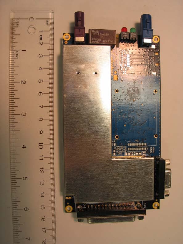
NJIAL250
Oct 06, 2004Vehicle Monitoring Transmitter Module
Equipment Class
TNB - Licensed Non-Broadcast Station Transmitter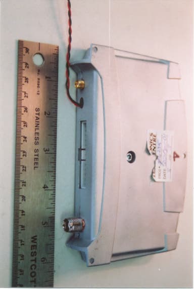
NJILOCA01
Dec 06, 2001GPS Receiver, Cellular Digital modem, I/O interfac
Equipment Class
TNB - Licensed Non-Broadcast Station Transmitter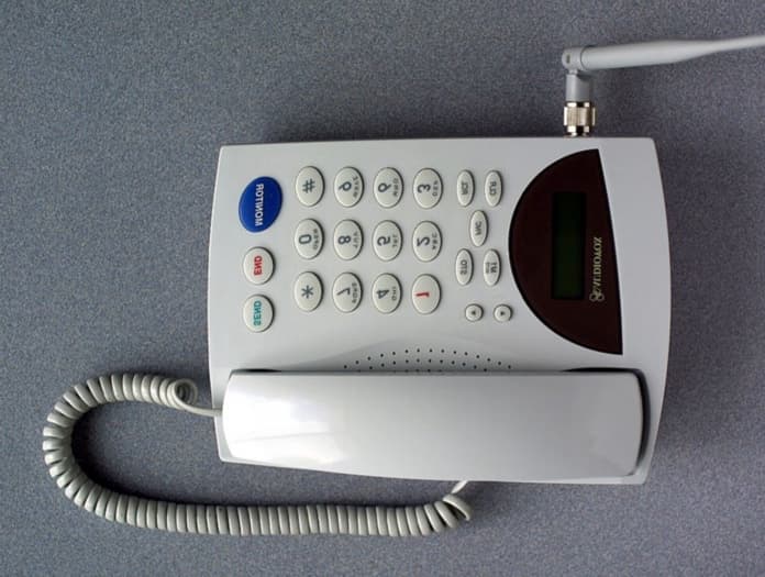
NJIFW8100
Jul 25, 2001Fixed Wireless Cellular Desktop Phone
Equipment Class
TNB - Licensed Non-Broadcast Station Transmitter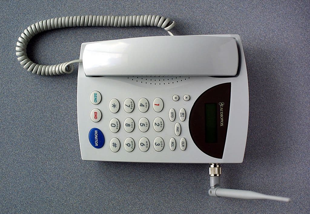
NJIFW8000
Jun 25, 2001Fixed Wireless Cellular Desktop Phone
Equipment Class
TNB - Licensed Non-Broadcast Station Transmitter