NJIFW8100Fixed Wireless Cellular Desktop Phone
CSI Wireless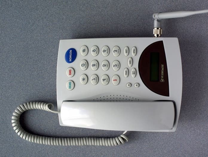
Click to zoom
Application Details
- Equipment Class
- TNB - Licensed Non-Broadcast Station Transmitter
- Date of Grant
- Jul 25, 2001
- Application Purpose
- Original Equipment
- Date of Application
- May 16, 2001
- Equipment Note
- Fixed Wireless Cellular Desktop Phone
- Frequency Range
- 824.04000000 - 848.97000000
- Company
- CSI Wireless
- Country
- United States
Documents & Files
Document Text
Text extracted from the exhibit documents filed with the FCC. Open a document above to read the original.
Users Manual
1/4140 Telian Corporation FWT-8100 and FWT-8000 Fixed Wireless Terminal May 1, 2001. 2/4140 Congratulations Your new cellular telephone is a carefully engineered, high quality, durable product with natural sound quality, modern features and elegant styling. It is designed to give you the quality and convenience you expect in a cellular telephone. To familiarize yourself with all the features of your new phone, please read the following instructions carefully. Retain this Guide for future reference. 3/4140 nnINTRODUCTION...............................................5 uSAFETY INFORMATION........................................................5 uFEATURES...............................................................................7 uDISPLAY INFORMATION..............................................7 uKEY AND MISCELLANEOUS INFORMATION 8 nnBASIC OPERATION................................11 uTURNING THE PHONE ON.......................................11 uMAKING AND RECEIVING CALLS.....................11 uREVIEWING THE PRECEDING DIGITS...........13 uREDIALING FUNCTIONS...........................................14 uMIC MUTE..........................................................................15 nnENHANCED OPERATION.................16 uLOCKING AND UNLOCKING THE PHONE...16 uEARPIECE VOLUME ADJUSTMENT.................16 uLOUDSPEAKER VOLUME ADJUSTMENT.....17 uMEMORY FUNCTIONS................................................18 uONE-TOUCH DIALING...............................................20 uONE-TOUCH EMERGENCY CALL.....................21 u911 EMERGENCY CALL.........................................2221 uSCRATCH PAD MEMORY.........................................22 uEMERGENCY AND PRIORITY DIALING........23 uRINGER MELODY...........................................................23 uTIME AND DATE...........................................................2423 uCALLER ID..........................................................................24 nnEXTENDED FEATURES AND FUNCTIONS...........................................................2524 uKEYPAD (DTMF) TONES........................................25 4/4140 uTIMER AND COUNTER FUNCTIONS.................26 uSYSTEM A/B INDICATION FOR AMPS.........29 uUSER PROGRAMMABLE CODES.........................29 uCHANNEL AND RSSI LEVEL DISPLAY.........30 uELECTRONIC SERIAL NUMBER (ESN).....3130 nnINSTALLATION..........................................31 uPARTS LIST..........................................................................31 uINCLUDED IN THE GIFTBOX..................................32 uGENERAL SPECIFICATIONS.....................33 TABLE OF KEY OPERATIONS........................34 5/4140 n INTRODUCTION u Safety Information As with any product, precautions should he observed during its handling and use. To become enlightened to safe and proper procedure, please read and adhere to all warnings, cautions, and safety information. l Avoid using the telephone during an electrical storm. There is a remote risk of dangerous electrical shock from lightning. l Do not attempt to disassemble the housing of your phone or any of its related parts. There are no user serviceable components. l A minimum distance of 2 inches should be kept between the telephone antenna and any organic life forms (i.e. people, small animals, etc.) during operations. l Damage Requiring Service : Your telephone should be serviced by qualified service personnel when: a. Objects have fallen or liquid has spilled into the product; or b. The product has been exposed to rain; or c. The product does not appear to operate normally or exhibits a marked change in performance; or d. The product has been dropped, or the housing has been damaged. l Never touch uninsulated telephone wires or terminals. ! Caution! NEVER power the unit without an antenna, as it may damage the radio transmitter. 6/4140 ! Caution! To satisfy FCC radio-frequency exposure requirements, the antenna for this device must be placed 2 inches (5 cm) or more from all persons, while it is in operation. 7/4140 u Features l Easy to read LCD display with numeric and status indicators l Back-lit LCD display l Microphone Mute Control l Priority/Emergency calling with automatic retry l Automatic call retry l 89 memory locations l 7 Location Scratch Pad, with automatic scroll l Vacant memory location search l Automatic entry into vacant memory location l Phone number search l One-Touch Dialing l One-Touch Emergency Call l Last 10 number dialed memory l Silent Incoming Calls l Call time warning tone l DTMF tone dialing from memory l DTMF keypad mute l DTMF extended tone dialing l RF Channel and RSSI Level display l Electronic serial number display (own) l Telephone number display (own) l System ID display (own) l 7 function call timer u Display Information 1 2 3 45 8/4140 Å Current Time Display Ç,É FUNCTION Mode Indicator and NUMBER Display Lights when the FUNCTION key FNC is pressed to do extended functions and Displays the telephone number dialed. Ñ AM/PM Display Ö Current Date Display u Key and Miscellaneous Information ABC 2 GHI 4 STO CLR PORS 7 TUV 8 WXYZ 9 # OPER 0 FNC 1 DEF 3 JKL 5 MNO 6 SEND RCL M1 END MONITOR 1 2 3 45 6 7 8 910 11 9/4140 12 13 14 15 1617 18 19 20 1 VOLUME ADJUSTMENT keys / Used to adjust the alert tone, earpiece, keypad tone and monitor volume level 2 ONE-TOUCH DIAL and MUTE key M1 In idle mode, allows you to place a call with a single keystroke. In conversation mode, switches off the microphone so the other party on the line cannot hear your private conversation off line. 3 STORE Key STO When used in conjunction with digit keys, enables the user to store number into memory. 4 FUNCTION Key FNC When used in conjunction with digit keys, allows operation of extended functions 5 CLEAR Key CLR 10/4140 Clear the digit(s) from the display. 6 RECALL Key RCL Recalls telephone numbers from memory. 7 ONE-TOUCH EMERGENCY Key 1 Allows you to place a call to an emergency number by a single keystroke 8 DIGIT Keys 1 thru OPER 0…
Text truncated - open the document above for the full version.
Users Manual
1365 Adams Court, Menlo Park, CA 94025 Wireless Link, Model No: FWT-8100 FCC ID: NJIFW8100 Date of Test: April 18 to April 23, 2001 Report # 20451372 16 of 91 FCC Part 22 Table 4.1b Frequency Deviation Frequency kHz Initial Deviation Peak Deviation Steady State Deviation 0.31.310.510.2 0.52.111.110.1 0.74.29.39.1 0.97.410.910.6 1.08.011.38.0 1.29.513.012.7 1.49.712.312.1 1.69.311.711.0 1.88.810.910.7 2.08.410.410.1 2.46.38.07.9 2.86.27.87.7 3.06.07.37.2 Test Conditions: V inp = 9.6 mV Deviation = 8 kHz at 1 kHz modulation frequency Middle Channel = 836.52 MHz 1365 Adams Court, Menlo Park, CA 94025 Wireless Link, Model No: FWT-8100 FCC ID: NJIFW8100 Date of Test: April 18 to April 23, 2001 Report # 20451372 17 of 91 FCC Part 22 5.0Audio Filter Characteristics FCC 22.915(d) For mobile stations, these signals must be attenuated, relative to the level at 1 kHz, as follows: (i)In the frequency ranges of 3.0 to 5.9 kHz and 6.1 to 15.0 kHz, signals must be attenuated by at least 40 log (f/3) dB, where f is the frequency of the signal in kHz. (ii)In the frequency range of 5.9 to 6.1 kHz, signals must be attenuated at least 35 dB. (iii)In the frequency range above 15 kHz, signals must be attenuated at least 28 dB. 5.1Test Procedure The test was performed according to the block diagram shown below. On that block diagram, the HP 3885A spectrum analyzer having the tracing generator, and the Marconi 2955A Radio Communication Test Set having an output of a FM demodulator, are used. After the calibration was made (the -20 dBm reading of the spectrum analyzer corresponds to the 9 kHz deviation) the spectrum analyzer was set to scan the frequency from 300 Hz to 30 kHz, with the same audio input level as described above, and with compressor OFF and expander OFF. The audio filter response was plotted directly from the spectrum analyzer (Refer to Plots # 5.1.a, 5.1.b). Transmitter RF out Audio in Marconi 2955A Test Set Spectrum Analyzer HP 3588A FM demodul. RF in Audio inAudio out 1365 Adams Court, Menlo Park, CA 94025 Wireless Link, Model No: FWT-8100 FCC ID: NJIFW8100 Date of Test: April 18 to April 23, 2001 Report # 20451372 18 of 91 FCC Part 22 Using the level measured at 1 kHz as a reference (0 dB), the audio filter response was calculated (See Table 5.1). Table 5.1 Audio Filter Characteristics Modulation Frequency kHz Relative Level dBm Attenuation 0.3-38.9517.8 0.4-36.1214.9 0.5-32.4711.2 0.6-30.276.2 0.7-27.45.2 0.8-24.943.7 0.9-23.532.3 1.0-21.210 1.2-19.59-1.7 1.4-19.26-2.0 1.6-19.45-1.8 1.8-20.08-1.2 2.0-20.68-0.6 2.2-21.15-0.1 2.5-21.890.6 3.0-23.341.1 3.5-28.517.3 4.0-59.2338.5 4.5-59.9838.7 5.0-60.3139.4 5.5-60.7739.5 5.9-61.6040.4 6.0-61.2040.2 6.1-60.7940.5 8.0-63.5042.3 10.0-64.2243.0 15.0-69.9848.7 20.0-85.3863.1 30.0-94.9872.7 5.2Test Equipment Marconi Instruments 2955A Radio Communications Test Set HP 3588A Spectrum Analyzer HP 7470A Plotter 1365 Adams Court, Menlo Park, CA 94025 Wireless Link, Model No: FWT-8100 FCC ID: NJIFW8100 Date of Test: April 18 to April 23, 2001 Report # 20451372 19 of 91 FCC Part 22 5.3Test Results Passed, refer to the attached plots. Audio Filter Characteristics Plot NumberDescription 5.3.a300Hz to 15KHz 5.3.b15KHz to 30KHz 1365 Adams Court, Menlo Park, CA 94025 Wireless Link, Model No: FWT-8100 FCC ID: NJIFW8100 Date of Test: April 18 to April 23, 2001 Report # 20451372 20 of 91 FCC Part 22 1365 Adams Court, Menlo Park, CA 94025 Wireless Link, Model No: FWT-8100 FCC ID: NJIFW8100 Date of Test: April 18 to April 23, 2001 Report # 20451372 21 of 91 FCC Part 22 1365 Adams Court, Menlo Park, CA 94025 Wireless Link, Model No: FWT-8100 FCC ID: NJIFW8100 Date of Test: April 18 to April 23, 2001 Report # 20451372 22 of 91 FCC Part 22 6.0Emission Limitations, Occupied Bandwidth FCC 2.1049, 22.917(b)(d) For F3E/F3D emission mask uses with audio filter, the mean power of emissions must be attenuated below the mean power of the unmodulated carrier wave (P) as follows: (1)On any frequency removed from the carrier frequency by more than 20 kHz but not more than 45 kHz: at least 26 dB; (2)On any frequency removed from the carrier frequency by more than 45 kHz, up to the first multiple of the carrier frequency: at least 60 dB or (43 + 10 log P) dB, whichever is the lesser attenuation. For F1D emission mask, the mean power of emissions must be attenuated below the mean power of the unmodualted carrier (P) as follows: (1)On any frequency removed from the carrier frequency by more than 20 kHz but no more than 45 kHz: at least 26 dB; (2)On any frequency removed from the carrier frequency by more than 45 kHz but not more than 90 kHz: at least 45 dB; (2)On any frequency removed from the carrier frequency by more than 90 kHz, up to the first multiple of the carrier frequency: at least 60 dB or (43 +10 log P) dB, whichever is the lesser attenuation. 6.1Test Procedure The RF output of the transceiver was connected to the input of the spectrum analyzer through sufficient attenuation. The audio generator was connected to the audio input of the transceiver. The spectrum with no modulation was recorded. The audio input signal was adjusted to obtain the frequenciy deviation equal 6 kHz at the audio frequency of maximum response which was determined measuring deviation versus frequency from 300 Hz to 3.5 kHz and was found 2.8 kHz. The audio input level was increased by 16 dB. The audio frequency was set to the frequency 2.5 kHz. The resolution bandwidth of the spectrum analyzer was set at 300 Hz and the spectrum was recorded in the frequency band ±50 kHz and ±100 kHz from the carrier frequency. The same plots has been done for wideband emissions, SAT, ST, DTMF9, Voice, some of the combinations of these modulating signals and in TDMA mode.
Cover Letter(s)
Wireless Link Corp. FWT-8100 Statement of Compliance With Electrical Serial Number (ESN) Regulations The Electrical Serial Number (ESN) is encrypted and stored in a non-volatile memory location. A non encrypted version of the ESN is stored in a separate location in the memory. Upon power up the software decrypts the encrypted ESN, using a key known only to Telian, and compares it to the non-encrypted version of ESN. If they do not match, the board sets ESN to all zeros and powers the board down. The ESN is set only by Telian factory and cannot otherwise be altered, transferred or removed. Any attempts to manipulate the ESN will render the phone inoperative.
Cover Letter(s)
Answers to FCC info request (Correspondence Reference Number 19763) 1.Output Power listed in SAR report (26.9dBm AMPS, 35.4dBm TDMA) is conducted measurement. This measurement data is corrected and shown in revised SAR report (27.2dBm AMPS mode and 35.4 TDMA mode). Refer to pages 5 and 15 of Exhibit “Revised SAR Test Report”. The conducted output power in the Part 22-test report is corrected. Refer to pages 4 and 5 of revised part 22 report at “ Revised Test Report”. Radiated power was re-measured. The new data is shown on page 13.Please replace old one with new one. 2. Form 731 is modified to reflect TDMA designator as 30K0DXW. 3. SAR reading are recalculated and plotted with corrected values conductivity and permitivity. Please see page 15, 17 and 23 to 28 of revised SAR report submitted as exhibit “Revised SAR Test Report”. The recalculated data can be considered as the worst case, because the SAR results are approximately 10% higher.
Cover Letter(s)
FEDERAL COMMUNICATIONS COMMISSION – FCC FORM 731 APPLICATION FOR EQUIPMENT AUTHORIZATION Applicant’s complete, legal business name: Wireless Link Applicant’s mail address: Line 1: 1909 Milmont Drive Line 2: P.O. Box: City: Milpitas State: CA Country(if foreign address): USAZip/Postal Code: 95035 FCC ID: Grantee code: NJI Equipment Product Code (14 characters maximum): FW8100 Person at the applicant’s address to receive grant or for contact First Name: EricMail Stop: Last Name: Maxon Line 1: 1909 Milmont DriveP.O. Box: Line 2: City: MilpitasState: CA Country (if foreign address): Zip/Postal Code: 95035 Telephone: 650/719-1100Ext: Fax No: 650/719-9646 Title: Email : [email protected] Instead of Applicant, TCB is authorized to mail original Grant to: Firm Name : Intertek Testing Services First Name: DavidLast Name: Chernomordik Title: EMC Site ManagerMail Stop: Item 6: Technical Contact: Firm Name : Intertek Testing Services Telephone: (650) 463-2900Ext: 2918Fax No: (650) 463-2910 First Na me: DavidMiddle Initia l: Last Name: Chernomordik Line 1: 1365 Adams CourtP.O. Box: Line 2: City: Menlo ParkState: CA Country (if foreign address): USAZip/Postal Code: 94025 Email : [email protected] Item 7: Non-Technical Contact: Firm Name : Intertek Testing Services Telephone: (650) 463-2900Ext: 2909Fax No: (650) 463-2910 First Na me: StephenieMiddle Initia l: J Last Name: Smith Line 1: 1365 Adams CourtP.O. Box: Line 2: City: Menlo ParkState: CA Country (if foreign address): USAZip/Postal Code: 94025 Email : [email protected] Item 8: Does this application include a request for confidentiality for any portion(s) of the data contained in this application pursuant to 47 CFR 0.459 of the commission Rules? If “ Yes” see instructions. Yes No Item 9: Does the applicant request that the Commission defer grant of this application pursuant 47 CFR 0.457(d)(1)(ii)? (See instruction) If so, specify date when grant may issued (MM?DD?YYYY) format: Yes No Item 10: Equipment Code: TNB Equipment will be operated under FCC Rule Part(s): 2,15, Description of Product as it is Marketed: Fixed Wireless Cellular Desktop Phone Item 11: Application is for Original Equipment Change in identification of presently authorized equipment Original FCC ID: Grant Date (MM/DD/YYY): Class II permissive change or modification of presently authorized equipment Item 12: Equipment Specifications: Frequency range in MHzRated RF power output in watts Frequency tolerance Emission designator Microprocessor Model number 824.04 848.97.4362.09 ppm4Ok0F8W 824.04 848.973.02.09 ppm3OK0DXW % Item 13: Is the equipment in this application (a) a composite device subject to an additional equipment authorization? (b) Part of a system that operates with, or is marketed with, another device that requires an equipment authorization? If either of the above questions is answered “Yes” complete section 13(c). YesNo YesNo (c) The related application: has filed at same time as this application under the FCC ID listed to the right. has been granted under the FCC ID listed to the right. is in the process of being filed under the FCC ID listed to the right. is pending with the FCC under the FCC ID listed to the right. FCC ID: Item 14. Name of the test firm and contact person on the file with the FCC, if different from applicant or contact person: Firm Name : Intertek Testing Services First Na me: DavidLast Name: Chernomordik Telephone: (650) 463-2900Ext: 2918Fax No.: (650) 463-2910 Email: [email protected] Read each certification carefully before answering and signing this application WILLFULL FALSE STATEMENT MADE ON THIS FORM ARE PUNISHABLE BY FINE AND IMPRISONMENT (U.S. CODE, TITLE 18, SECTION 1001), AND/OR REVOCATION OF ANY STATION LICENSE OR CONSTITUTION PERMIT (U.S. CODE, TITLE 47, SECTION 312(a)(1)), AND/OR FORFEITURE (U.S. CODE, TITLE 47, SECTION 503) Item 15. SECTION 5031 (ANTI-DRUG ABUSE) CERTIFICATION: The applicant must certify that neither the applicant nor any party to the application is subject to a denial of Federal benefits, that include FCC benefits, pursuant to Section 5301 of the Anti-Drug Abuse Act of 1988, 21 U.S.C. 862 because of a conviction for possession or distribution of a controlled substance. See 47 CFR 1.2002(b) for the definition of a “party” for these purposes. Does the applicant or authorized agent so certify? Yes No Item 16. APPLICANT/AGENT CERTIFICATION: I certify that I am authorized to sign this application. All of the statements herein and the exhibits attached hereto, are true and correct to the best of my knowledge and belief. In accepting a Grant of Equipment Authorization issued by the FCC as a result of the representations made in this application, the applicant is responsible for (1) labeling the equipment with the exact FCC ID specified in this application, (2) compliance statement labeling pursuant to the applicable rules, and (3) compliance of the equipment with the applicable technical rules. If the applicant is not the actual manufacturer of the continue to comply with the FCC’s technical requirement. Authorizing an agent to sign this application is done solely at applicant’s discretion; however, the applicant remains responsible for all statements in this application. If an agent has signed this application on behalf of the applicant, a written letter authorization which includes information to enable the agent to respond to the above section 5301 (Anti-Drug Abuse) Certification statement has been provided by the applicant. It is understood that the letter of authorization must be submitted to the FCC upon request and that the FCC reserves the right to contac t the applicant directly at any time. Signature of Authorized Person Filing: David Chernomordik Title of Authorized Signature: EMC Site Manager Complete items below if an agent signs the application Firm Name : Intertek Testing Services Telephone: (650) 463-2900Ext: 2918Fax No: (650) 463-2910 First Name: David Middle Initial: Last Name: Chernomordik Line 1: 13…
Text truncated - open the document above for the full version.
External Photos
EUT External Photo FCC ID: NJIFW8100 EUT External Photo FCC ID: NJIFW8100 External Photo Bottom FWT-8100, FCC ID NJIFW8100 External Photo Top FWT 8100, FCC ID NJIFW8100
ID Label/Location Info
External Photo Bottom FWT-3100, FCC ID NJIFW8100
Operational Description
Page 1 of 2 FWT- 8100 PRELIMINARY Fixed Wireless Product, 800 MHz Overview The Fixed Wireless Product is a stand-alone telephone with digital TDMA and analog AMPS cellular transceiver radio system built-in. It provides extended telephone service bringing subscriber wireless access to a cellular network. Cellular Specifications • Fully compliant with AMPS and TIA/EIS/IS-136.1A, 800 MHz TDMA Cellular Radio Interface. • Power Output: Up to 3.0 watts TDMA, 0.6 watts AMPS • Frequencies: 824.04 to 848.97 MHz, transmit 869.04 to 893.97 MHz, receive • Number of channels 832 Page 2 of 2 • Memory locations 102 ( 9 speed dial, 80 general purpose, 7 scratchpad, 1 Priority / Emergency, 1 One-Touch (M1 key), 1 One-Touch emergency , 3 most recently dialed.) • Memory Capacity 32 digits per location Speaker • Conversation can be monitored by depressing ‘‘Speaker’’ key. Locking • A 3-digit code is used to lock and unlock the unit. When in the locked state, calls can be received, but no calls can be dialed out other than security bypass numbers. (One-touch emergency, Priority/Emergency, 911, 119, 000). Operating Voltage / Power • Source: 6V external power supply (AC to DC Adapter supplied). Transmit: 1.5A maximum, Standby (Receive): 200Ma • Automatic Battery Back-up: If AC power is lost, 4 – 1.5V AA alkaline batteries (not included) provide up to 30 minutes talk time. Interfaces / Connectors • via DC socket • TNC Antenna Connector Physical Specifications • Size: 8.75” x 6.375” x 1.69” (220 mm x 165 mm x 50 mm) • Weight: 1.84 pound (836 grams) • Installation: Desk top or wall mountable with optional mounting bracket Environmental Specifications • Temperature: 0° °° °C to +60° °° °C operating -40°C to +70°C storage Optional Accessories • Wall mount bracket 1909 Milmont Drive Milpitas CA 95035 Phone: 408 719-1100 FAX: 408 719-9646 www.wireless-link.com
Operational Description
Test results for FWT-8100 Fixed Wireless Terminal Frequency Stability vs. Temperature Date of Test: April 11, 2001 Test Engineer: Shahrokh Zardoshti Unit Serial Number: 005 Test Equipment: HP 8920B Radio Test Set Temperature Chamber, -50°C to +100°C HP E3630A Power Supply Test Method: The unit under test was connected to an external power supply set at 4.8 volts and the RF output connected to the HP 8920B via a calibrated coaxial cable. The unit under test was placed inside the temperature chamber and the DC leads and RF output cable exited the chamber through an opening made for that purpose. The chamber was allowed to stabilize for 20 minutes at each temperature before each frequency and power reading was taken with the HP 8920B. A printout from the HP 8920B is included for reference. Test was done in AMPS mode. Tx Frequency: 836.01 MHz Tolerance: +/- 2091 Hz Temperature (°C) Frequency (MHz) Difference (“ Hz) Output Power (dBm) 60836.009280-72021.24 50836.0100494921.94 40836.01017917922.70 30836.009917-8323.41 20836.009694-30623.73 10836.009581-41924.58 0836.009800-20025.15 -10836.01074073826.06 -20836.011404140426.62 -30836.011578157827.40
Operational Description
Date:05-15-01 FIXED WIRELESS 3W TEST PROCEDURE. 1-Take a look at the board and make sure IC’s are in right position. 2-Use a Multimeter and measure for a short on FL2 any side of it. Make sure is not shorted. If there is short remove FL2 and measure which side is short. It is usually on P.A side U62. Replaced the P.A. 3-Place the test board on top of the main board to be programmed and tested. Main board that I am using does not have any component on it The main board has a connector hanging with five wires connected to board. Connector should be connected to the level shifter which from the other side is connected to computer. Also make sure the power for PA is connected to supply and if is not you have to put external wire from pin 1 of connector (+4V) to FL2. Use a thick wire. 4-Turn the Computer on. It should have CellCom software program installed in it. Latest CellCom version is 4.23. When you open the CellCom on top left hand side is a configure logo. Use the mouse and click on it. There is option for comport. Select the comport and make sure your comport that is connected to interface box is configured as follow, speed 115200, data bit 8, parity none and stop bits 1. 5-After you set everything press OK, close the window to go back to main window. 6-For programming fixed TDMA you need a special loader in software to ignore RTS. Now we are ready to start programming the unit. 7-Select power Supply with 2.5A current limiting and set it to +4 volt. 8-There are two connector in back of level shifter, with symbols of GND for ground and + for positive voltage which should be connected to power supply. 9- Turn on the power Supply unit should be drawing around 60mA. If unit current is more than 200mA. We need to find which Regulator is shorted. U20 pin 5 should be 3 volt, U28 pin 5 should be 3.2 volt, U21 pin 5 should be 2.8 volt, U26 pin 5 should be 3 volt, U9 pin 8 should be 3 volt and U10 pin 8 should be 2.5 volt. 10-To program the unit we select the program Logo, is on top left hand side of CellCom window. After window open we can see the name of program in yellow section under New Firmware select. The program we looking for called Tdm3000-john-3-16.bin or the latest software. If there is another program in this window use Browse to find the right one then select it and open it, by selecting open. Now start programming by selecting program firmware on green section of window. Sometimes program will ask you to reset the unit then just turn off and back on the power Supply, and select OK. 11- If there is a problem with programming, using scope probe we have to check level of clock for controller. R89, TCXO2 (19.44MHZ) 1volt DC, 1 volt peak to peak. R88, TCXO, 2.2 volt DC, 180mV peak to peak and R204 TCXO1, 2volt DC, 800mV peak to peak, if there is no clock check VC1 Pin 2 for clock. If still there is no clock replace VC1. 12- If unit get programmed and everything goes OK. You will see, Press OK. 13-Now you can see all kind of activity on CellCom window. Unit should be drawing around 160 to 250mA. It depends if the radio transmit to some receiving signals. 14-To start testing the board we have to set frequency channel. We do this by selecting, setting on top right hand side of CellCom window and we set them to, click on Send to phone, and exit. 15-Now we have to set the NAM, to select NAM go to top right hand side of CellCom and click on NAM and set NAM as follows, put any 10 digit for phone number, SID set it to 31 and in bottom put any number for ESN and Mfg’s code, click on set and then click on send to phone and exit. If you want to use HP8920B equipment for automated test make sure Primary paging channel is set to 333. 16-For testing we are going to use IFR 1900. We need a power splitter. From source of splitter connect to the unit(TDMA), one split goes to IFR and other split end with 20 dB Attenuation goes to Gigatronics 8651A power meter. Now we need to calibrate level that goes to the unit. Turn IFR ON, push RF GEN. on IFR set frequency to 881 MHZ at –10dBm, Deviation 0. Remove power meter and connect it to source side of splitter, terminate split side with 50 Ohm. See how much loss you have( it should be between 4 to 6 dB) from IFR side to radio this is for receive calibration write this down. Move the power meter back to splitting end and put a signal generator to the source of splitter at 836 MHZ, -10dBm and look from split end that goes to power meter with 20dB Attenuation how much loss you have( it should be around 4 to 6 dB loss). This is for transmit loss. 17-Now press DPLX key on IFR, select Sp tst(F5), 3 for DCCH Cell SITE SIMULATION, F1 for BROADCAST CHANNEL MESSAGE. Use arrow key to go to MSG TYPE, Turn the knob till you get to SYSTEM IDENTITY, press ENTER key. Make sure SID is set to 31, If is not change it to 31. Push RET(F6) to go back. Press F3 for call processing. In this screen set Channel to 367, U8( for cellular band), RfLVL –65dBm, RATE full, Type digital, IDT 2, MIN ..(anything), CHAN 367 , slot 1, DMAC 6, DVCC 68, SB 0, TA 0, PV 0, DIC 1, VC 2ACELP, SIGAL PITCH MED, CADENCE 000001, and rest zero. 18-Connect back all the connectors to splitter, output of TDMA to source, one end of splitter to IFR and other end with 10dB attenuation to spectrum Analyzer. 19-Now if the unit is ON just do the RESET on top left hand side of CellCom. If unit is off, turn on the power supply. Reset the unit again. 20-Now If every thing is working we will see the screen bellow. To be able to see every thing, make sure on left hand side of CellCom Auto Status and Monitor are checked on. If you have a green indication for the channel on left hand side of CellCom window, that means your receive side is working. Reduce the RF level on IFR to –105dBm, There should be no more than 3% to 4%BER indication on left hand side of CellCom window. If OK go to step 21. If there are more than 4% we have to check receive path. If the indication is red, this means you are not synch to signal, we have…
Text truncated - open the document above for the full version.
Operational Description
Test results for FWT-8100 Cellular Fixed Wireless Terminal Frequency Stability vs. Battery Voltage Date of Test: April 10, 2001 Test Engineer: Shahrokh Zardoshti Unit Serial Number: 005 Test Equipment: HP 8920B Radio Test Set HP E3630A Power Supply Test Method: The unit under test was connected to an external power supply and the RF output connected to the HP 8920B via a calibrated coaxial cable. The power supply was varied from 3.4 volts to 4.5 volts and the frequency and TX power recorded on the HP 8920. Printouts from the HP8920 at each voltage is recorded for reference. Test was done in AMPS mode. Tx Frequency: 836.01 MHz Tolerance: +/- 2091 Hz Supply (Battery) Volts Frequency (MHz) Difference (“ Hz) Output Power (dBm) 3.8836.0100868625.80 4.0836.01012912926.00 4.4836.01017617626.25 4.9836.01020020026.34
Operational Description
1 5/10/01 Theory of Operation 1.0 General Radio Technical Description The frequency plan for this Dual-Mode handset was developed to satisfy the following conditions: 1. Minimum number of local oscillators in the product (one VC-TCXO* and two oscillators). 2. All on-board oscillators locked to the same reference (VC-TCXO) i.e. no free running signals in the product. * TCXO (VC1): The frequency for this TCXO is 19.44 MHz and is powered from 3.0v regulator U26. The overall frequency variatio n is +/- 2.5ppm over the temperature range of -30 ° C to +60 ° C. This TCXO also has an …
Text truncated - open the document above for the full version.
Contact Information
Applicant
Eric Maxon(Program Director)
Technical Contact
Intertek Testing ServicesDavid Chernomordik
[email protected]650/463-2900
1365 Adams Court · Menlo Park, California · United States
Non-Technical Contact
Intertek Testing ServicesCourtney Kemp
[email protected]650/463-2900
Test Firm
Intertek Testing Services NA Inc.John Quigley
Technical Specifications
| # | Rule Parts | Frequency Range | Power Output | Emission | Tolerance |
|---|---|---|---|---|---|
| 3 | 22.901(d) | 824.04 MHz - 848.97 MHz | 3 W | 30KODXW | 2.09 ppm |
Other Applications from CSI Wireless
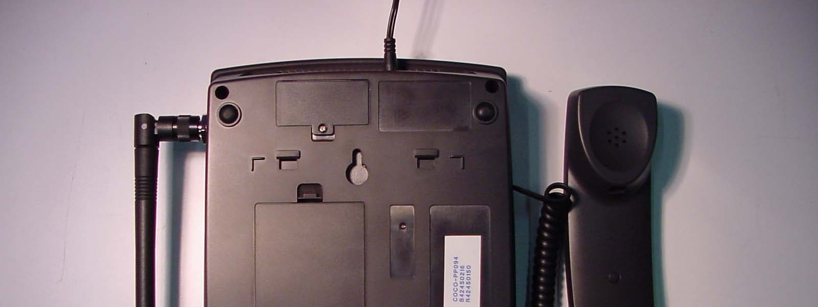
NJIFW1900
Nov 14, 2004GSM Fixed Wireless Phone
Equipment Class
PCB - PCS Licensed Transmitter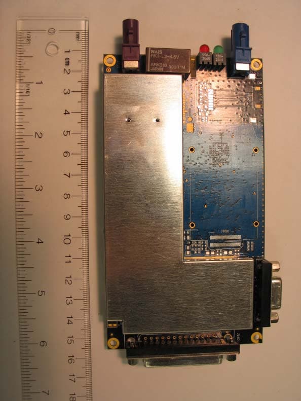
NJIAL250
Oct 06, 2004Vehicle Monitoring Transmitter Module
Equipment Class
TNB - Licensed Non-Broadcast Station Transmitter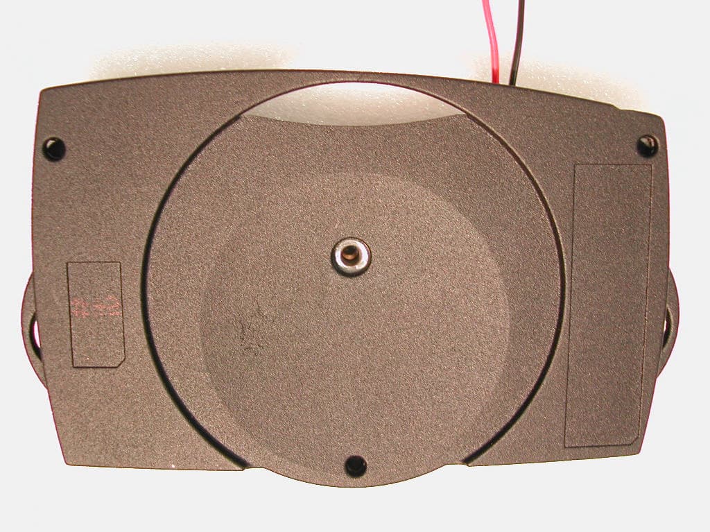
NJIAL200
Jan 27, 2002AssetLink 200
Equipment Class
TNB - Licensed Non-Broadcast Station Transmitter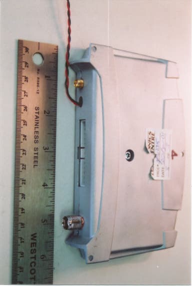
NJILOCA01
Dec 06, 2001GPS Receiver, Cellular Digital modem, I/O interfac
Equipment Class
TNB - Licensed Non-Broadcast Station Transmitter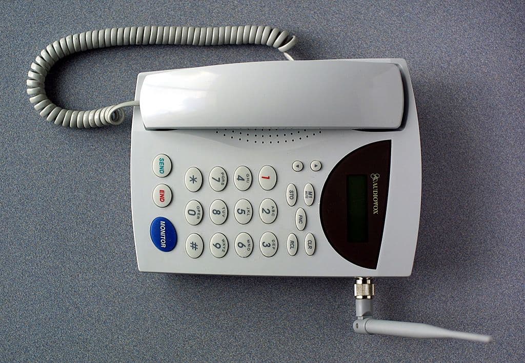
NJIFW8000
Jun 25, 2001Fixed Wireless Cellular Desktop Phone
Equipment Class
TNB - Licensed Non-Broadcast Station Transmitter