NLCAXRRJ01BRAID Redundent Mass Storage Device
Advanced Technology and Systems Co Ltd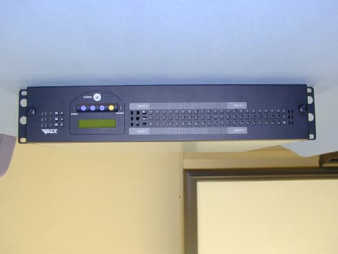
Click to zoom
Application Details
- Equipment Class
- JBP - Part 15 Class B Computing Device Peripheral
- Date of Grant
- Feb 07, 2001
- Application Purpose
- Original Equipment
- Date of Application
- Feb 07, 2001
- Equipment Note
- RAID Redundent Mass Storage Device
- Country
- Japan
Documents & Files
Document Text
Text extracted from the exhibit documents filed with the FCC. Open a document above to read the original.
Users Manual
ArrayMasStor J Series (19” Rack Model, Tower Model ) USER’S MANUAL P/N A208233 Revision 1.2e Advanced Technology and Systems Co., Ltd. II WARNING l The AC power cord must be connected to a grounded outlet. In case of a short-circuit, electrical shock or fire may occur. l Do not use the ArrayMasStor in hot, humid or dusty environments. Usage under such conditions may result in a short circuit, electrical shock or fire. l The ArrayMasStor's cover must be securely attached to the chassis. If the cover is not properly installed, ventilation could be impaired and this may cause a short circuit, electrical shock or fire. l Do not block the ventilation opens. Without proper ventilation, the ArrayMasStor will malfunction or fail. l Use the supplied AC power cord. In case of a short circuit, electrical shock or fire may occur. CAUTION l Rapid temperature changes may cause condensation of humidity to form on the ArrayMasStor. Do not use the subsystem where it will not evaporate. l Do not install the ArrayMasStor near electronic components with strong electromagnetic fields, such as televisions or loud speakers. l Turn off the power before moving, connecting or disconnecting the ArrayMasStor. This will prevent vibrations or mechanical shocks from damaging the hard disk drives (HDD) and other internal components. l Do not remove the drive unit during normal operation, as this may cause damage, malfunction or data loss. The drive unit should be removed when they have failed and need to be replaced. l Use the appropriate SCSI host card for ArrayMasStor in accordance with single-ended or low voltage differential (LVD) SCSI interface. Using the wrong card may damage the subsystem or cause a malfunction to occur. l Use only the approved replacement drive unit in the ArrayMasStor. Please see Appendix D for a list of approved replacement parts. ArrayMasStor J Series User’s Manual III l Do not turn on and off in a rapid succession manner. Leave at least 15 seconds between turning on and off. This may avoid damage or malfunction. The HDD requires about 15 seconds to completely stop after turning off the ArrayMasStor. l Insert to push the drive unit firmly. A loose connection may damage the ArrayMasStor or cause it to malfunction. l Do not turn the ArrayMasStor off by unplugging the AC power cord from the rear panel. This may result in data loss. The ArrayMasStor’s firmware is designed to detect the status of the power switch and synchronize the data in the cache and the drives before shutdown. To control the power from the AC line, send a ‘synchronize cache’ 1 command from the host computer to the ArrayMasStor. l When unplugging the AC power cord, leave one minute further before plugging it again. This may prevent fuse damage. IMPORTANT ! l For optimum performance, the total length of the SCSI bus should be as short as possible. The total cable length must be less than 1.5 m for single-ended mode and 12m for LVD mode. l A maximum of two host computers can be connected to the ArrayMasStor in a dual host configuration. l Set the ArrayMasStor’s UNIX 2 C/H/S mode before connecting it to the operating systems shown below. Changing the UNIX C/H/S mode after installation may cause data loss. Solaris 3 (SPARC) 2.X IRIX 4 5.X l The backlight on the liquid crystal display (LCD) turns off automatically when the operation buttons are not used for a period of time. The backlight will turn on when the operation button is pressed. The backlight will stay on when a drive fails, when the ArrayMasStor is in data reconstruction mode, and during data initialization. 1 A SCSI command which ensures that logical blocks in the cache have their most recent data value recorded in the drives. 2 UNIX has two known standards, System V by AT&T and BSD4.x by Berkeley University. 3 Solaris™ and Spark™ is a Trademark of SUN Microsystems. 4 IRIX ™ is a Trademark of Silicon Graphics Inc. Advanced Technology and Systems Co., Ltd. IV l It is strongly recommended that up to two ArrayMasStors be connected to the same bus in the single-ended SCSI. l It is strongly recommended that the data be regularly backed up. In RAID levels 1 and 5, the ArrayMasStor will be operative when a drive fails. However, if two or more drives fail, all of the data may not be recoverable. And, if any other parts of the ArrayMasStor malfunction, there is possibility of data loss. l It is strongly recommended that the surface verification check implement before dynamic data reallocation. l It is strongly recommended that an interruptible power supply (UPS) be used with the ArrayMasStor to avoid data loss when the power line is unstable and power outrage happens. ArrayMasStor J Series User’s Manual V Table of Contents Foreword ....................................................................................................................................I Safety Notice ..............................................................................................................................I WARNING................................................................................................................................II CAUTION.................................................................................................................................II IMPORTANT...........................................................................................................................III 1INTRODUCTION TO THE ARRAYMASSTOR J SERIES............................................................1 1.1FEATURES......................................................................................................................................1 1.2ABOUT RAID LEVELS....................................................................................................................2 1.2.1RAID Level 0..........................................................................................................................2 1.2.2RAID Level 1..................................…
Text truncated - open the document above for the full version.
External Photos
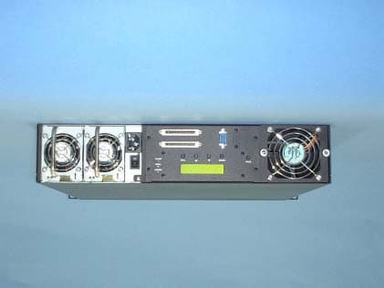
External Photos Front side Back side Right side Left side Top side Bottom side
ID Label/Location Info
Top side Bottom side Top Bottom Fig. 1 Label to be attached on the product
Internal Photos
Internal photos Front panel removed Top panel removed Power supply unit removed Power supply unit Main module Main module (The other side)
Test Report
Test report No. : 21FE0012-YK-2 Page: 2 of 16 Issued date: February 6, 2001 A-pex International Co., Ltd. YAMAKITA LAB. 907 Kawanishi, Yamakita-machi, Ashigarakami-gun, Kanagawa-ken, 258-0124 JAPAN Telephone:int +81 465 77 1011 Facsimile:int +81 465 77 2112 CONTENTS PAGE SECTION 1 :Client information3 SECTION 2 :Equipment under test (E.U.T.)3 SECTION 3 :Test specification, methods & procedures4 SECTION 4 :Operation of E.U.T. during testing5 SECTION 5 :Summary of test results7 SECTION 6 :Test instruments10 SECTION 7 :Conducted emission11 SECTION 8 :Radiated emission 12 APPENDIX 1:Photographs of test setup13 APPENDIX 2:Data of EMI test 16 Test report No. : 21FE0012-YK-2 Page: 3 of 16 Issued date: February 6, 2001 A-pex International Co., Ltd. YAMAKITA LAB. 907 Kawanishi, Yamakita-machi, Ashigarakami-gun, Kanagawa-ken, 258-0124 JAPAN Telephone:int +81 465 77 1011 Facsimile:int +81 465 77 2112 SECTION 1: Client information Company Name: Advanced Technology and Systems Co., Ltd. Brand Name: ADTX Address: 9F East Tower, Yokohama Bisiness Park 134, Gohdo-cho Hodogaya-ku, yokohama-shi, Kanagawa Japan Telephone Number: +81-45-334-0040 Facsimile Number: +81-45-334-0094 Contact Person: Tetsushi Kobayashi SECTION 2: Equipment under test (E.U.T.) 2.1Identification of E.U.T. Unique Type Identification: RAID Subsystem Model No.: AXRR-J764SS Rating: AC100/240V, 50Hz/60Hz, 150W Country of Manufacture: JAPAN Receipt Date of Sample : January 26,27, 2001 2.2Product description Advanced Technology and Systems Co., Ltd. , Model: AXRR-J764SS (referred to as the EUT in this report) is a RAID Subsystem. The clock frequency used in EUT is 15MHz, 20MHz, 40MHz, 60MHz, 80MHz. RAID 0, 1, 0+1, 5 Dual Power Supply HDD/Power Supply/FAN Hot swap support Ultra2 SCSI Interface (MAX 40MB/sec translate) 2channel SCSI Interface AXRR-J764SS has series models. The way of naming of a series model is as follows. AXRR-JnnnS ** n : 0 to 9, * : Blank or A to Z AXRR-J764SS is the highest rank model. See the user’s manual Appendix A for the details. Test report No. : 21FE0012-YK-2 Page: 5 of 16 Issued date: February 6, 2001 A-pex International Co., Ltd. YAMAKITA LAB. 907 Kawanishi, Yamakita-machi, Ashigarakami-gun, Kanagawa-ken, 258-0124 JAPAN Telephone:int +81 465 77 1011 Facsimile:int +81 465 77 2112 SECTION 4: Operation of E.U.T. during testing 4.1Operating modes The EUT exercise program used during testing was designed to exercise the various system components in a manner similar to typical use. The sequence is used: Random Read/Write Operation: Windows NT4.0 data file read/write by Xcopy command. Justification:The system was configured in typical fashion (as a customer would normally use it) for testing. 4.2Configuration and peripherals Front View *Cabling was taken into consideration and test data was taken under worse case conditions. Top View *Cabling was taken into consideration and test data was taken under worse case conditions. A:EUT IH C B DE F G K J LM 12 3 4 5 6 7 8 9 10 11 12 13 1415 16 17 18 1920212223 AC120V/60Hz AC100V/50Hz AC100V/50Hz AC100V/50Hz AC120V/60HzAC100V/50HzAC100V/50Hz AC100V/50Hz 12 3 4 56 78 9 10 11 12 13 14 15 16 17 18 19 20 212223 A:EUT B C D E F G H I KJ L M Test report No. : 21FE0012-YK-2 Page: 8 of 16 Issued date: February 6, 2001 A-pex International Co., Ltd. YAMAKITA LAB. 907 Kawanishi, Yamakita-machi, Ashigarakami-gun, Kanagawa-ken, 258-0124 JAPAN Telephone:int +81 465 77 1011 Facsimile:int +81 465 77 2112 5.1.2 Data of radiated emission test The initial step in collecting radiated data was a spectrum analyzer peak scan of the measurement range (30MHz-1000MHz). The final data was reported in the worst-case emissions. The minimum margin to the limit is as follows : ReceiverCorrectionField FrequencyReadingFactorStrengthLimitMargin (MHz)(dBuV)(dB/m)(dBuV/m)(dBuV/m) (dB) 95.9550.0 -9.840.243.53.3 * All readings are quasi-peak mode. Field strength calculation The field strength is calculated by adding the Antenna Factor, Cable Factor and Antenna Pad, and subtracting the Amplifier Gain from the measured reading. The sample calculation is as follows : FS = RA + AF + CF + AT - AG Correction factor where FS = Field Strength RA = Receiver Amplitude AF = Antenna Factor CF = Cable Factor AT = Antenna Pad AG = Amplifier Gain Assume a receiver reading of 50.0dBuV is obtained. The antenna Factor of 10.0dB, Cable Factor of 2.4dB and Antenna Pad of 6.0dB is added. The Amplifier Gain of 28.2dB is subtracted, giving a field strength of 40.2dBuV/m. FS = 50.0 + 10.0 + 2.4 + 6.0 – 28.2 = 40.2dBuV/m Test report No. : 21FE0012-YK-2 Page: 9 of 16 Issued date: February 6, 2001 A-pex International Co., Ltd. YAMAKITA LAB. 907 Kawanishi, Yamakita-machi, Ashigarakami-gun, Kanagawa-ken, 258-0124 JAPAN Telephone:int +81 465 77 1011 Facsimile:int +81 465 77 2112 5.2Uncertainty Conducted emission test The measurement uncertainty (with a 95% confidence level) for this test was +2.0dB. The data listed in this test report has enough margin, more than 2.0dB. Radiated emission test The measurement uncertainty (with a 95% confidence level) for this test was +3.3dB. The data listed in this test report has enough margin, more than 3.3dB. 5.3Test instruments Refer to SECTION 6: TEST INSTRUMENTS 5.4Test location A-PEX International Co.,Ltd. Yamakita No.1 Open Test Site. 907, Kawanishi, Yamakita-machi, Ashigarakami-gun, Kanagawa-ken 258-0124 Japan Telephone number: +81-465-77-1011 Facsimile number: +81-465-77-2112 This site has been fully described in a report dated September 24, 1999 submitted to FCC office, and accepted in a letter dated October 8, 1999 (95486) NVLAP Lab. code200441-0 5.5Photographs of test setup Refer to Appendix 1. 5.6Data of EMI test Refer to Appendix 2. Test report No. : 21FE0012-YK-2 Page: 11 of 16 Issued date: February 6, 2001 A-pex International Co., Ltd. YAMAKITA LAB. 907 Kawanishi, Yamakita-machi, Ashigarakami-gun, Kanagawa-ken, 258-0124 JAPAN Telephone:int +81 465 77 1011 Facsimile:int +81 465 77 2112 SECTION …
Text truncated - open the document above for the full version.
Test Setup Photos
Test report No. : 21FE0012-YK-2 Page: 13 of 16 Issued date: February 6, 2001 A-pex International Co., Ltd. YAMAKITA LAB. 907 Kawanishi, Yamakita-machi, Ashigarakami-gun, Kanagawa-ken, 258-0124 JAPAN Telephone:int +81 465 77 1011 Facsimile:int +81 465 77 2112 APPENDIX 1: Photographs of test setup This section contains the following photographs: Page 14 :Conducted emission Page 15 :Radiated emission Test report No. : 21FE0012-YK-2 Page: 14 of 16 Issued date: February 6, 2001 A-pex International Co., Ltd. YAMAKITA LAB. 907 Kawanishi, Yamakita-machi, Ashigarakami-gun, Kanagawa-ken, 258-0124 JAPAN Telephone:int +81 465 77 1011 Facsimile:int +81 465 77 2112 Conducted emission Test report No. : 21FE0012-YK-2 Page: 15 of 16 Issued date: February 6, 2001 A-pex International Co., Ltd. YAMAKITA LAB. 907 Kawanishi, Yamakita-machi, Ashigarakami-gun, Kanagawa-ken, 258-0124 JAPAN Telephone:int +81 465 77 1011 Facsimile:int +81 465 77 2112 Radiated emission
Contact Information
Applicant
Yoshihiko Fujioka(Senior Manager)
045-334-0040Fax: 045-334-0094
Technical Contact
A-PEX International Co., Ltd.Tetsuya Hashimoto
[email protected]+81 465 77 1011
907 Kawanishi · Kanagawa-ken · Japan
Non-Technical Contact
A-PEX International Co.,Saori Inoue
[email protected]+81 465 77 1011
Test Firm
UL Apex Co., Ltd.Tetsuya Hashimoto
Technical Specifications
| # | Rule Parts | Frequency Range | Power Output |
|---|---|---|---|
| 1 | 15B | - | - |
Other Applications from Advanced Technology and Systems Co Ltd
NLCAXRRK01D
Mar 10, 2002RAID Data Storage Computer
Equipment Class
JBC - Part 15 Class B Computing Device/Personal Computer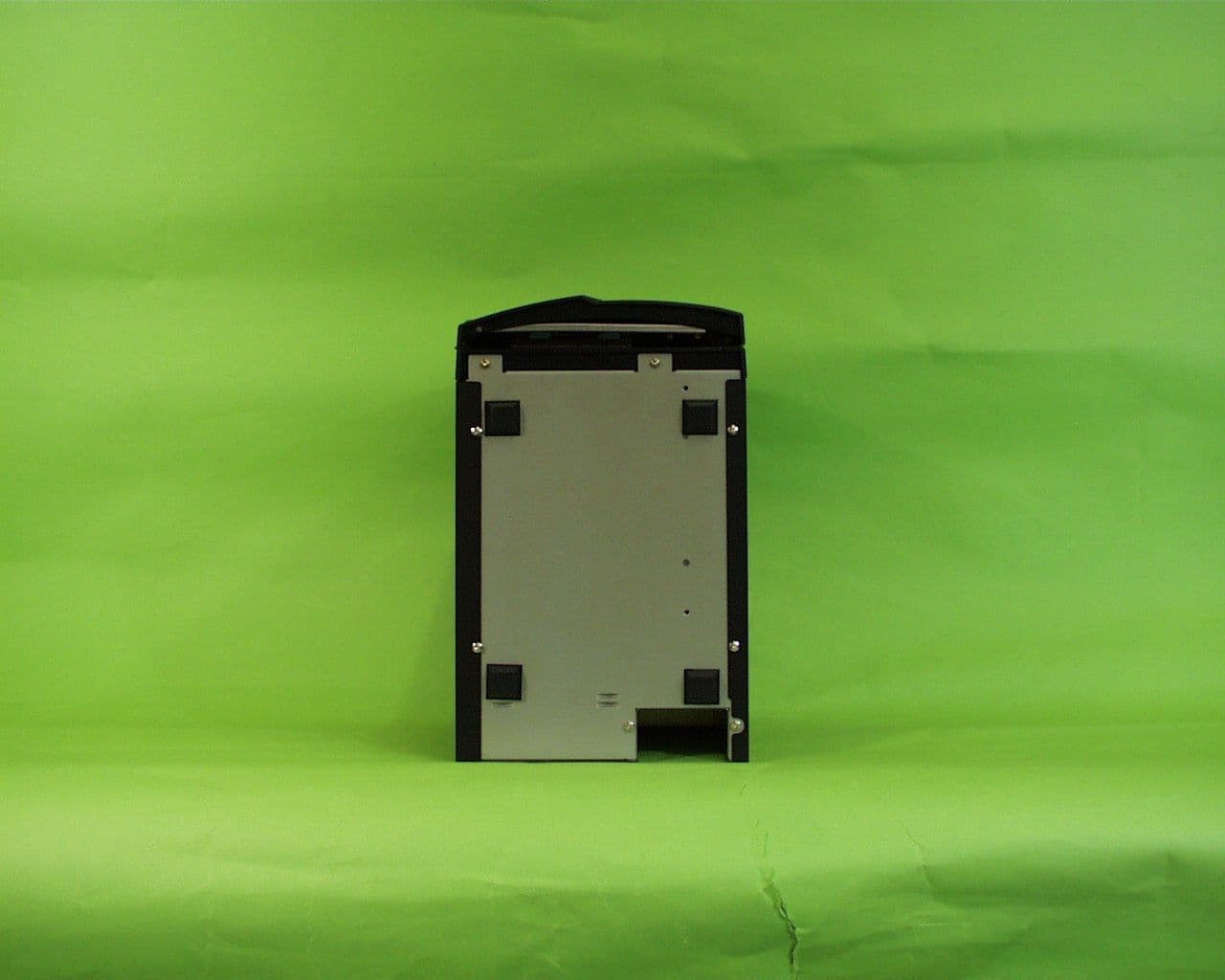
NLCAXRSJ01B
Jul 06, 2000SCSI External HDD
Equipment Class
JBC - Part 15 Class B Computing Device/Personal ComputerNLCAXRSF01A
Oct 08, 1997JBP - Part 15 Class B Computing Device Peripheral
Equipment Class
JBP - Part 15 Class B Computing Device Peripheral