NLCAXRRK01DRAID Data Storage Computer
Advanced Technology and Systems Co Ltd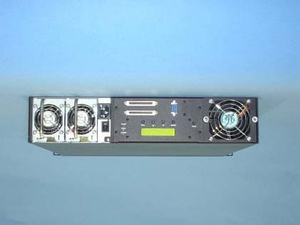
Click to zoom
Application Details
- Equipment Class
- JBC - Part 15 Class B Computing Device/Personal Computer
- Date of Grant
- Mar 10, 2002
- Application Purpose
- Original Equipment
- Date of Application
- Mar 10, 2002
- Equipment Note
- RAID Data Storage Computer
- Country
- Japan
Documents & Files
Document Text
Text extracted from the exhibit documents filed with the FCC. Open a document above to read the original.
Users Manual
” 2001 Advanced Technology and Systems Co., Ltd. 13715 Alton Parkway Irvine, CA 92618 Tel (949) 583-2993 ArrayMasStor “K” Series Installation Manual and Users Guide ArrayMasStor K Series “Installation Instructions and Procedures.” Copyright ” Advanced Technology and Systems Co., Ltd., 11/2001 Rev. A Trademarks and Trade name that may appear within this document are the property of their respective owners. Introduction .............................................................................................................................. 2 K-SERIES PRODUCT FEATURES.................................................................................................. 2 Unpacking the RAID system .................................................................................................... 3 P ACKING LIST.......................................................................................................................... 3 Installing the RAID system....................................................................................................... 3 SCSI T ERMINATION................................................................................................................. 4 Installing the Front panel cover ...............................................................................................5 HOST SCSI REQUIREMENTS...................................................................................................... 5 Operating the RAID system ..................................................................................................... 5 Front panel status indicators (LEDs)....................................................................................... 7 Front “Fresh air” intakes ......................................................................................................... 8 Rack mounting the RAID unit ................................................................................................. 8 Identifying rear panel components .......................................................................................... 9 Product Components ..............................................................................................................10 RAID C ONTROLLER............................................................................................................... 10 IDE D RIVE BAYS AND DRIVE TRAY ASSEMBLIES.................................................................... 10 POWER SUPPLIES.................................................................................................................... 10 FANS...................................................................................................................................... 10 ENCLOSURE............................................................................................................................ 10 RAID Overview ...................................................................................................................... 11 Non-RAID Storage ............................................................................................................. 11 About RAID levels .................................................................................................................. 12 RAID 0.................................................................................................................................. 12 RAID 1.................................................................................................................................. 12 RAID 1 (0+1) ..................................................................................................................... 13 RAID 3.................................................................................................................................. 13 RAID 5.................................................................................................................................. 13 Spare drives in RAID configurations..................................................................................... 14 RAID Rebuilding .................................................................................................................... 14 Removing a Drive from the RAID system (with power off) .................................................. 15 Removing a Power Supply from the RAID system (with power off) .................................... 17 ArrayMasStor K Series “Installation Instructions and Procedures.” Copyright ” Advanced Technology and Systems Co., Ltd., 11/2001 Rev. A Trademarks and Trade name that may appear within this document are the property of their respective owners. REDUNDANT POWER SUPPLIES................................................................................................ 17 RAID controller functions ......................................................................................................19 RAID C ONTROLLER BUTTON FUNCTIONS................................................................................. 19 RAID CONTROLLER CONNECTORS.......................................................................................... 20 Using the RAID Controller Functions ................................................................................... 21 B ASIC FEATURES.................................................................................................................... 21 Front Panel Ready Mode.................................................................................................... 21 Front Panel Configuration Options ....................................................................................... 22 Auto RAID Setup.................................................................................................................... 23 A DVANCED FUNCTIONS.......................................................................................................... 23 Selecting RAID Levels .…
Text truncated - open the document above for the full version.
Users Manual
Electronic Emission Notices Federal Communications Commission (FCC) Statement Note: This equipment has been tested and found to comply with the limits for a Class B digital device, pursuant to part 15 of the FCC Rules. These limits are designed to provide reasonable protection against harmful interference in a residential installation. This equipment generates, uses and can radiate radio frequency energy and, if not installed and used in accordance with the instructions, may cause harmful interference to radio communications. However, there is no guarantee that interference will not occur in a particular installation. If this equipment does cause harmful interference to radio or television reception, which can be determined by turning the equipment off and on, the user is encouraged to try to correct the interference by one or more of the following measures: -Reorient or relocate the receiving antenna -Increase the separation between the equipment and receiver. -Connect the equipment into an outlet on a circuit different from that to which the receiver is connected. -Consult the dealer or an experienced radio/TV technician for help. FCC WARNING Properly shielded and grounded cables and connectors must be used in order to meet FCC emission limits. Proper cables and connectors are available from ADTX authorized dealers or contributor. ADTX is not responsible for any radio or television interference caused by using other than recommended cables and connectors or by unauthorized changes or modifications to this equipment. Unauthorized changes or modifications could void the user's authority to operate the equipment.
External Photos
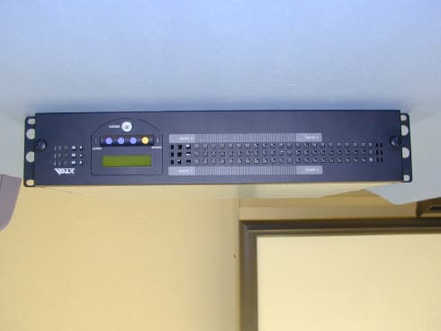
External Photos Advanced Technology and Systems Co., Ltd. Front side Back side Right side Left side Top side Bottom side
Internal Photos
Internal Photos Advanced Technology and Systems Co., Ltd. Front Panel Removed Top Panel Removed Disk Unit Disk Unit (Other side) Power Supply Unit Removed Power Supply Unit Main Module Main Module (The other side)
Test Report
Test report No. : 22GE0004-YK-2 Page : 2 of 22 Issued date : February 28, 2002 FCC ID : NLCAXRRK01D A-pex International Co., Ltd. YAMAKITA LAB. 907 Kawanishi, Yamakita-machi, Ashigarakami-gun, Kanagawa-ken, 258-0124 JAPAN Telephone: int +81 465 77 1011 Facsimile: int +81 465 77 2112 CONTENTS PAGE SECTION 1 : Client information 3 SECTION 2 : Equipment under test (E.U.T.) 3 SECTION 3 : Test specification, methods & procedures 4 SECTION 4 : Operation of E.U.T. during testing 5 SECTION 5 : Summary of test results 7 SECTION 6 : Conducted emission 9 SECTION 7 : Radiated emission 10 APPENDIX 1: Photographs of test setup 12 APPENDIX 2: Test instruments 14 APPENDIX 3: Data of EMI test 15 Test report No. : 22GE0004-YK-2 Page : 3 of 22 Issued date : February 28, 2002 FCC ID : NLCAXRRK01D A-pex International Co., Ltd. YAMAKITA LAB. 907 Kawanishi, Yamakita-machi, Ashigarakami-gun, Kanagawa-ken, 258-0124 JAPAN Telephone: int +81 465 77 1011 Facsimile: int +81 465 77 2112 SECTION 1: Client information Company Name : Advanced Technology and Systems Co., Ltd. Brand Name : ADTX Address : 9F, East Tower, Yokohama Business Park, 134 Gohdo-cho, Hodogaya-ku, Yokohama-shi, Kanagawa-ken, 240-0005, Japan Telephone Number : +81-45-334-0040 Facsimile Number : +81-45-334-0094 Contact Person : Katsuya Suzuki SECTION 2: Equipment under test (E.U.T.) 2.1 Identification of E.U.T. Regulation(s) : FCC Part 15 Subpart B Type of Equipment : Array MasStor-K Series Model No. : AXRR-K616S Serial No. : FCC sample FCC ID : NLCAXRRK01D Rating : AC:100-240V, 50Hz/60Hz, 1.4A Condition of EUT : Production model Country of Manufacture : Japan Tested Date : February 15, 2002 Receipt Date of Sample : February 14, 2002 2.2 Product description Advanced Technology and Systems Co., Ltd., Model: AXRR- KS (:0-9 or blank) (referred to as the EUT in this report) is a Array MasStor-K Series. The clock frequency used in EUT is Base clock:14.318MHz/40MHz/66MHz The inside Clock of CPU:100MHz Ultra160 SCSI of maximum data transmission speed 160 MB/sec Loading (Theoretical value) RAID 0, 0+1, 5 Power Supply → Dual Test report No. : 22GE0004-YK-2 Page : 4 of 22 Issued date : February 28, 2002 FCC ID : NLCAXRRK01D A-pex International Co., Ltd. YAMAKITA LAB. 907 Kawanishi, Yamakita-machi, Ashigarakami-gun, Kanagawa-ken, 258-0124 JAPAN Telephone: int +81 465 77 1011 Facsimile: int +81 465 77 2112 SECTION 3: Test specification, methods & procedures 3.1 Test specification Test Specification : FCC Part 15 Subpart B Title : FCC 47CFR Part 15 Radio Frequency Device Subpart B Unintentional Radiators 3.2 Methods & Procedures No. Item Test Procedure Limits Remarks 1 Conducted emission ANSI C63.4:1992 class B - 2 Radiated emission ANSI C63.4:1992 class B Test Distance:3m No addition, deviation nor exclusion have been made from standards. Test report No. : 22GE0004-YK-2 Page : 5 of 22 Issued date : February 28, 2002 FCC ID : NLCAXRRK01D A-pex International Co., Ltd. YAMAKITA LAB. 907 Kawanishi, Yamakita-machi, Ashigarakami-gun, Kanagawa-ken, 258-0124 JAPAN Telephone: int +81 465 77 1011 Facsimile: int +81 465 77 2112 SECTION 4: Operation of E.U.T. during testing 4.1 Operating modes The EUT exercise program used during testing was designed to exercise the various system components in a manner similar to typical use. Test sequence is used : Standby mode (Conducted emission test only) Random Read/Write mode Operation : File Copy Operation at Windows 2000 Justification : The system was configured in typical fashion (as a customer would normally use it) for testing. 4.2 Configuration and peripherals Front View *Cabling was taken into consideration and test data was taken under worse case conditions. Top View *Cabling was taken into consideration and test data was taken under worse case conditions. :Ferrite Core 1 2 3 4 5 6 7 8 9 10 11 12 A:EUT B C D E F G A:EUT B C D E F G 5 6 1 2 3 4 7 8 9 10 11 12 :Ferrite Core AC:120V/60Hz AC:100V/50Hz AC:120V/60Hz AC:120V/60Hz AC:120V/60Hz AC:120V/60Hz AC:100V/50Hz AC:120V/60Hz AC:120V/60Hz Test report No. : 22GE0004-YK-2 Page : 6 of 22 Issued date : February 28, 2002 FCC ID : NLCAXRRK01D A-pex International Co., Ltd. YAMAKITA LAB. 907 Kawanishi, Yamakita-machi, Ashigarakami-gun, Kanagawa-ken, 258-0124 JAPAN Telephone: int +81 465 77 1011 Facsimile: int +81 465 77 2112 Description of EUT and support equipment No. Item Model number Serial number Manufacturer FCC ID A ArrayMasStor-K Series AXRR-K616S - CORE MICRO SYSTEMS INC. (FCC sample) B PC VECTRA VL410 SF SG20307179 HP D.O.C. C Monitor 6540-02E 66-R4737 IBM H41CM14018 D Scanner ScanJet5200C SG933160ZC HP D.O.C. E Printer BJ-F100 ETB09986 CANON D.O.C. F Keyboard SK-2502C M011225194 HP D.O.C. G Mouse NOM-1 LZE14654691 HP JNZ201213 Meshed column are represented EUT List of cables used No. Name Length (m) Shield Backshell material 1 SCSI cable 12.0 Shielded Polyvinyl Chloride 2 Serial cable 3.0 Shielded Polyvinyl Chloride 3 USB cable 1.8 Shielded Polyvinyl Chloride 4 Pararell cable 2.0 Shielded Polyvinyl Chloride 5 Mouse cable 1.8 Unshielded Polyvinyl Chloride 6 Keyboard cable 1.8 Unshielded Polyvinyl Chloride 7 Monitor cable 1.5 Unshielded Polyvinyl Chloride 8 AC power cable for EUT 1.8 Unshielded Polyvinyl Chloride 9 AC power cable for Scanner 1.8 Unshielded Polyvinyl Chloride 10 AC power cable for PC 1.8 Unshielded Polyvinyl Chloride 11 AC power cable for Printer 1.8 Unshielded Polyvinyl Chloride 12 AC power cable for Monitor 1.8 Unshielded Polyvinyl Chloride Test report No. : 22GE0004-YK-2 Page : 7 of 22 Issued date : February 28, 2002 FCC ID : NLCAXRRK01D A-pex International Co., Ltd. YAMAKITA LAB. 907 Kawanishi, Yamakita-machi, Ashigarakami-gun, Kanagawa-ken, 258-0124 JAPAN Telephone: int +81 465 77 1011 Facsimile: int +81 465 77 2112 SECTION 5: Summary of test results 5.1 Test results No. Item Test Procedure Limits Worst margin Results 1 Conducted emission ANSI C63.4:1992 class B Standby mode 5.3dB (0.5178MHz:L1) complied 2 Radiated emission ANSI C63.4:1992 class B 2.6dB (20…
Text truncated - open the document above for the full version.
Test Setup Photos
Test report No. : 22GE0004-YK-2 Page : 12 of 22 Issued date : February 28, 2002 FCC ID : NLCAXRRK01D A-pex International Co., Ltd. YAMAKITA LAB. 907 Kawanishi, Yamakita-machi, Ashigarakami-gun, Kanagawa-ken, 258-0124 JAPAN Telephone: int +81 465 77 1011 Facsimile: int +81 465 77 2112 Conducted emission Test report No. : 22GE0004-YK-2 Page : 13 of 22 Issued date : February 28, 2002 FCC ID : NLCAXRRK01D A-pex International Co., Ltd. YAMAKITA LAB. 907 Kawanishi, Yamakita-machi, Ashigarakami-gun, Kanagawa-ken, 258-0124 JAPAN Telephone: int +81 465 77 1011 Facsimile: int +81 465 77 2112 Radiated emission
Contact Information
Applicant
Yoshihiko Fujioka(Senior Manager)
045-334-0040Fax: 045-334-0094
Technical Contact
A-Pex International Co LtdOsamu Watatani
[email protected]81 465 77 1011
907 Kawanishi, Yamakita-machi · Ahigara-gun, Kanagawa-ken · Japan
Non-Technical Contact
A-PexMotomu Kawano
[email protected]81-596-24-8116
Test Firm
UL Japan, IncMitsuru Fujimura
Technical Specifications
| # | Rule Parts | Frequency Range | Power Output |
|---|---|---|---|
| 1 | 15B | - | - |
Other Applications from Advanced Technology and Systems Co Ltd
NLCAXRRJ01B
Feb 07, 2001RAID Redundent Mass Storage Device
Equipment Class
JBP - Part 15 Class B Computing Device Peripheral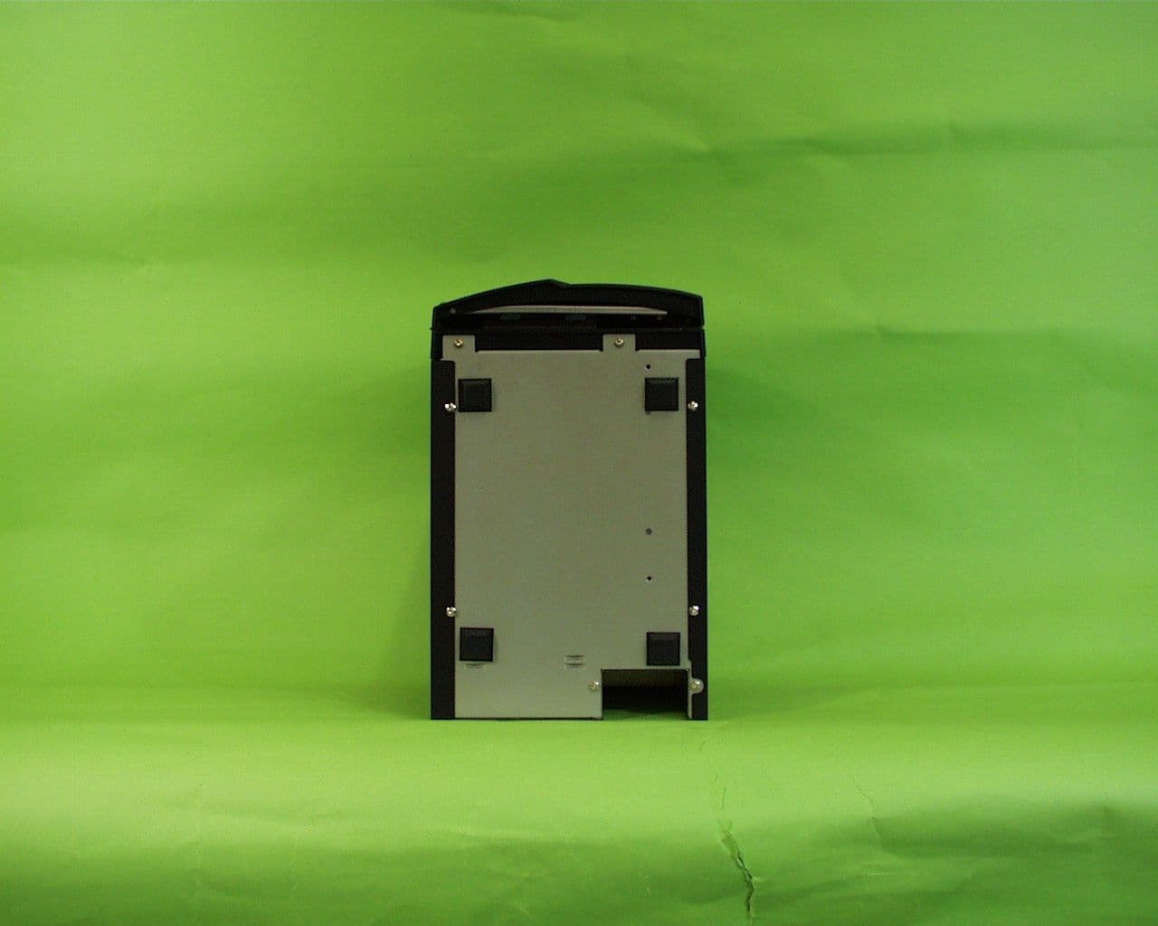
NLCAXRSJ01B
Jul 06, 2000SCSI External HDD
Equipment Class
JBC - Part 15 Class B Computing Device/Personal ComputerNLCAXRSF01A
Oct 08, 1997JBP - Part 15 Class B Computing Device Peripheral
Equipment Class
JBP - Part 15 Class B Computing Device Peripheral