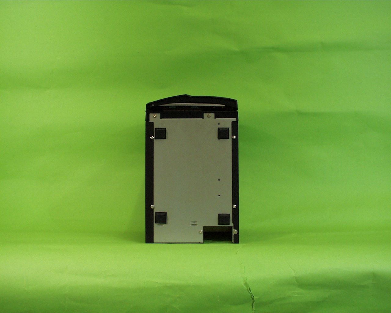
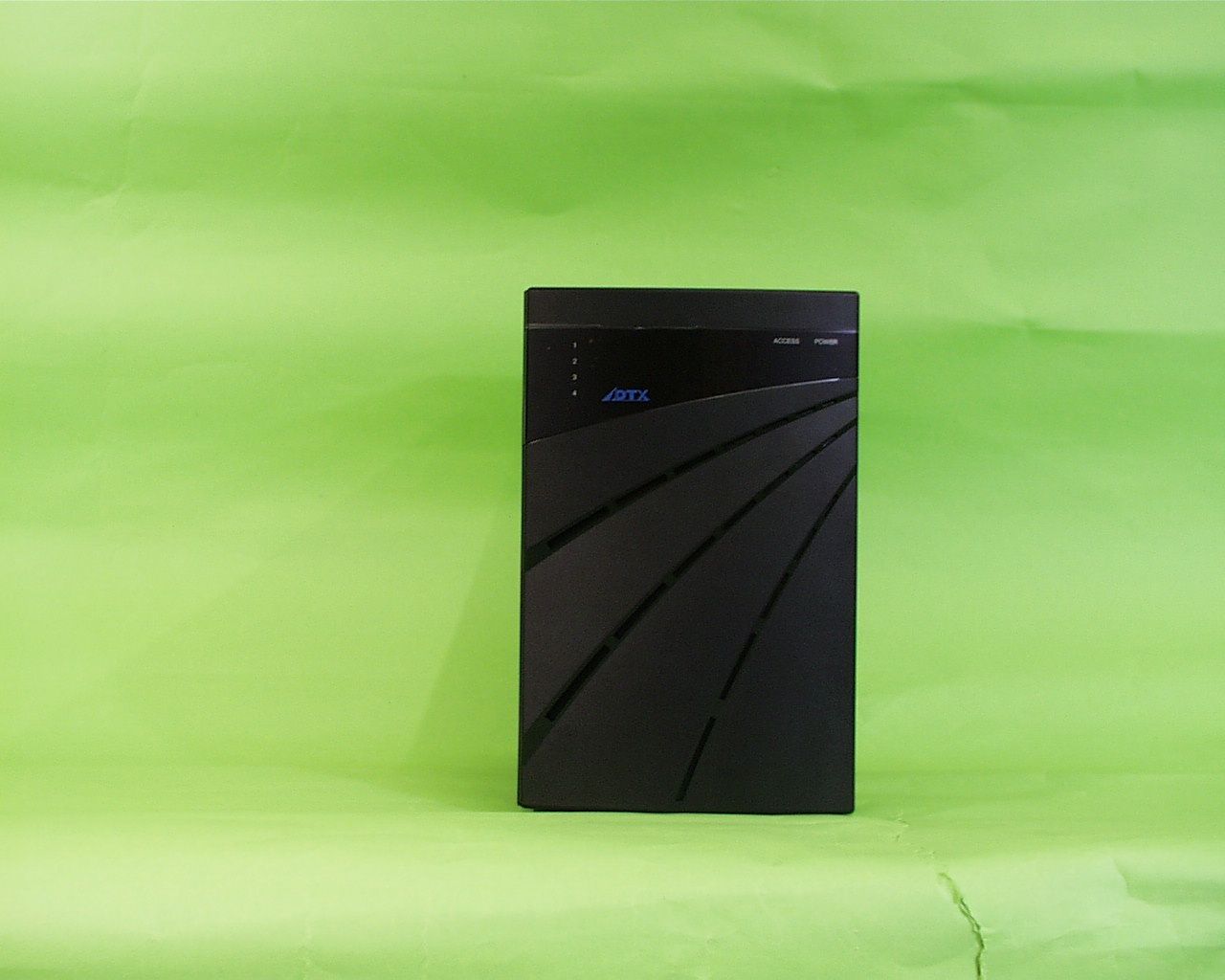
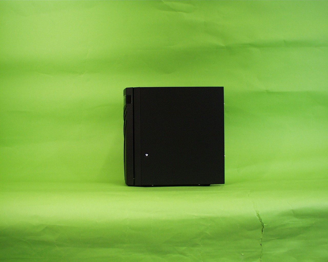
NLCAXRSJ01BSCSI External HDD
Advanced Technology and Systems Co Ltd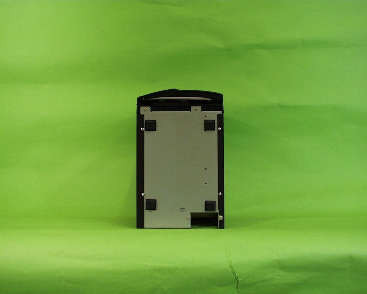
Click to zoom
Application Details
- Equipment Class
- JBC - Part 15 Class B Computing Device/Personal Computer
- Date of Grant
- Jul 06, 2000
- Application Purpose
- Original Equipment
- Date of Application
- Jun 13, 2000
- Equipment Note
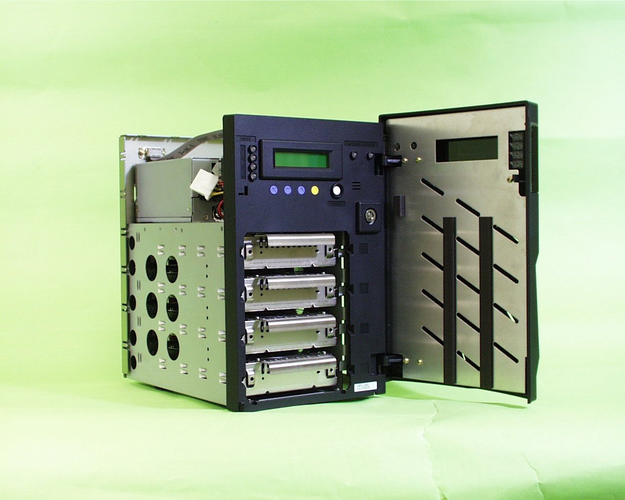
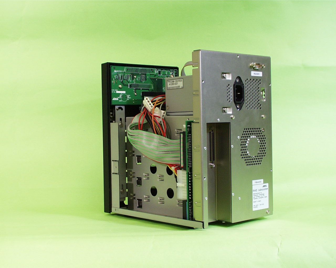
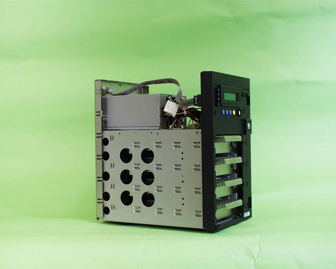
- SCSI External HDD
- Country
- Japan
Documents & Files
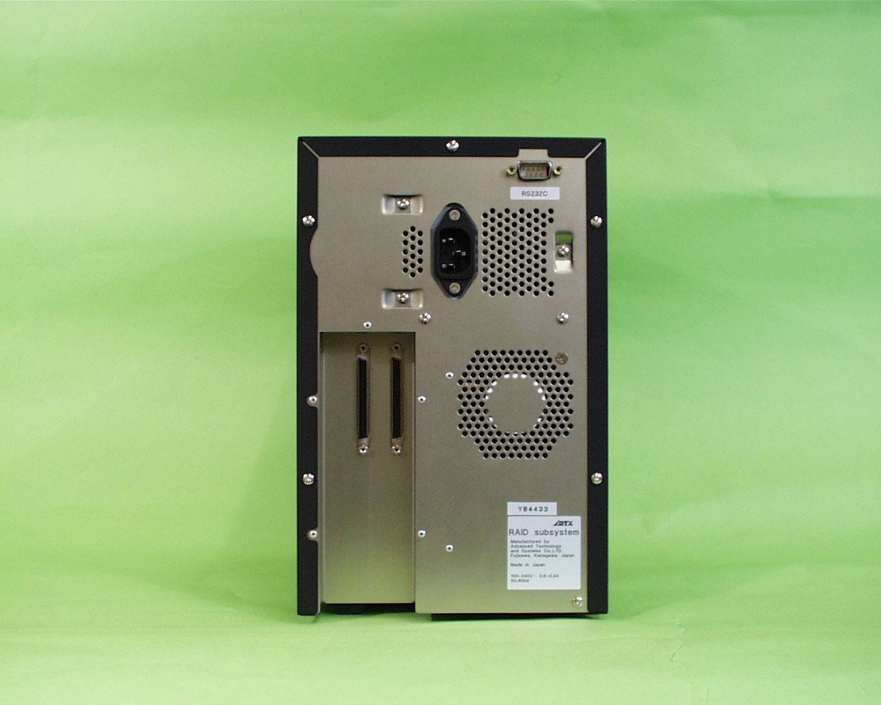
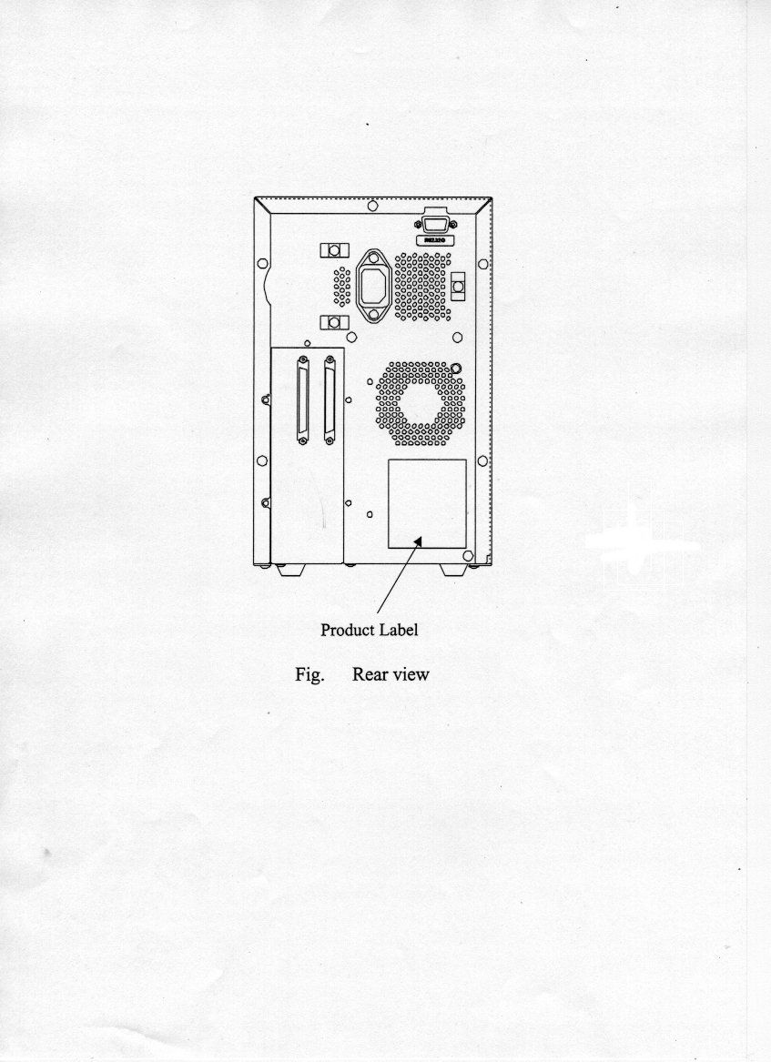
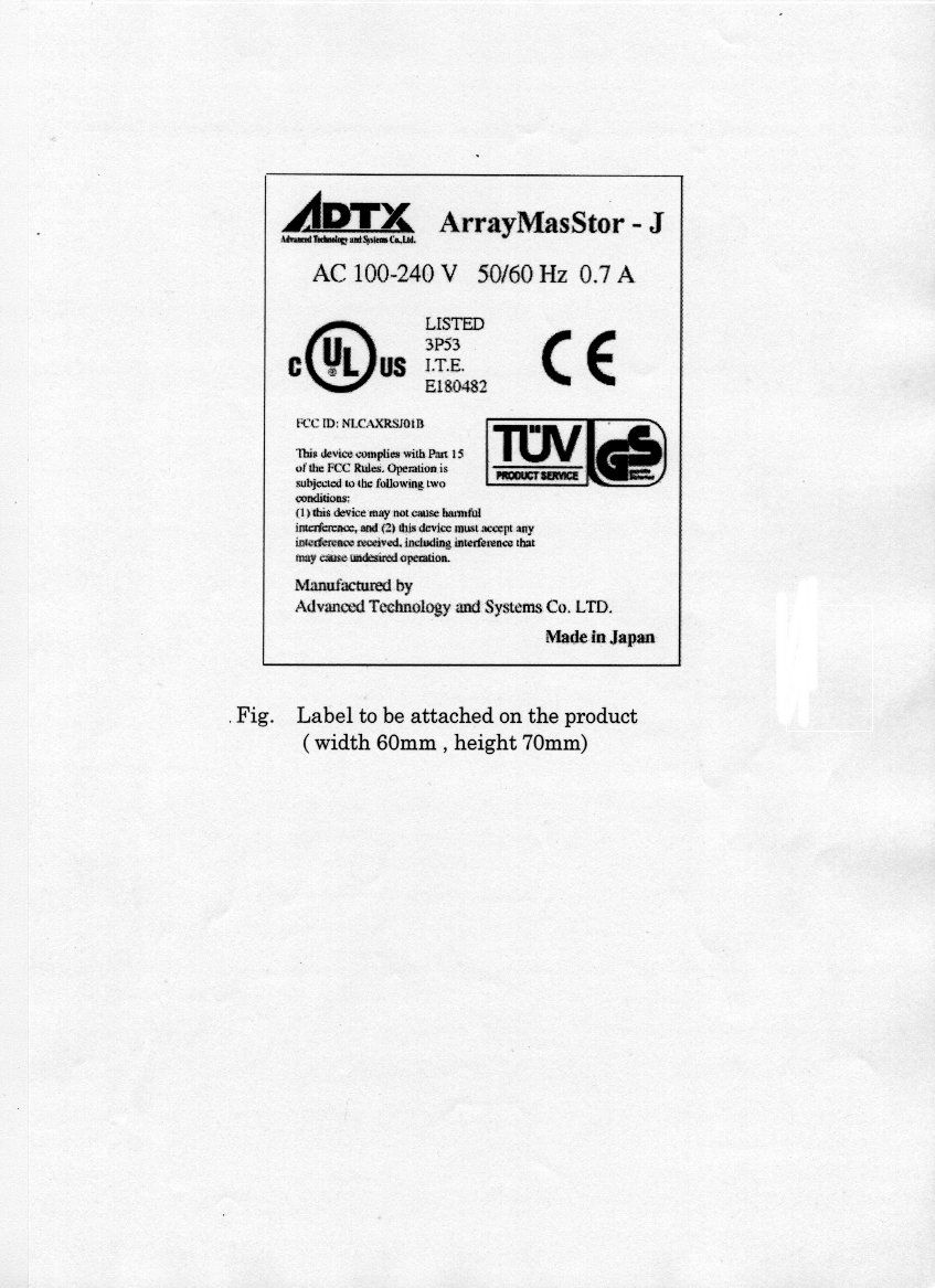
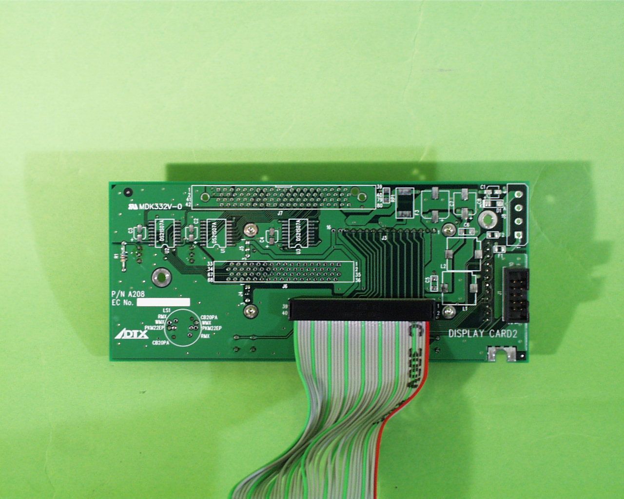
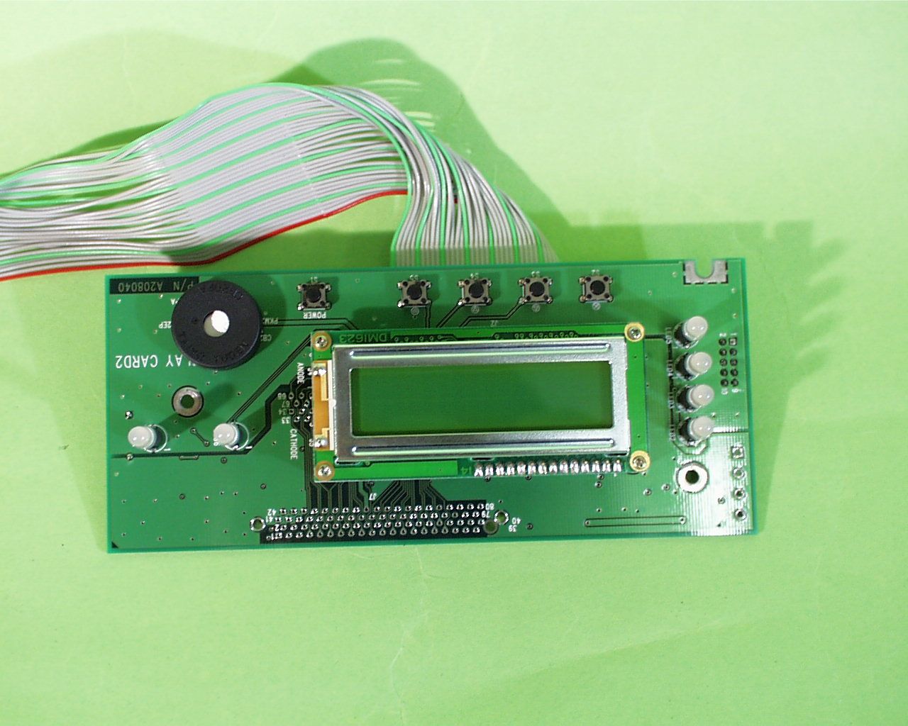
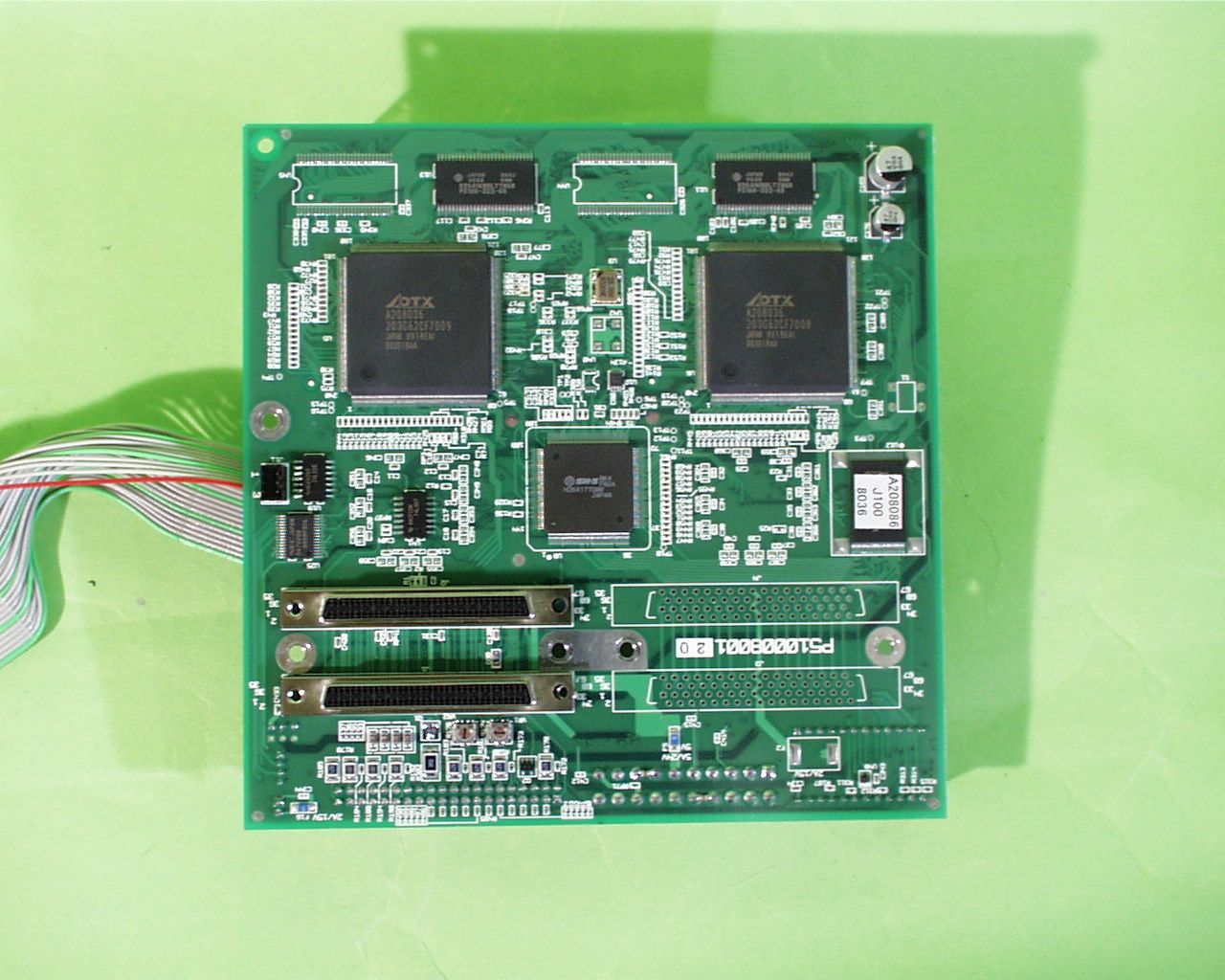
Document Text
Text extracted from the exhibit documents filed with the FCC. Open a document above to read the original.
Users Manual
ArrayMasStor J Series USER’S MANUAL P/N A208067 Revision 1.3e ArrayMasStor J Series User’s Manual I Foreword Thank you for purchasing ADTX’s ArrayMasStor J Series subsystem. This manual describes the operation, functions, and specifications of the ArrayMasStor J Series. Please read the manual before using this product. Safety Notice Throughout this manual the following symbols are used to highlight safety notice. WARNING Indicates a potentially hazardous situation, which could result in death or serious injury to the user or severe damage to the product. CAUTION Indicates a potentially hazardous situation, which could result in serious injury to the user or damage to the product. IMPORTANT ! Indicates an important information, which could result in erroneous operation to the product. • ArrayMasStor is a registered trademark of Advanced Technology and Systems Co., Ltd. • Macintosh, and Mac OS are trademarks of Apple Computer Inc. in the United States. • Solaris and SPARC4 are trademarks of SUN Microsystems Corporation in the United States. • IRIX is a trademark of Silicon Graphics Inc. • RS/6000, PowerPC, and AIX are trademarks of IBM Corporation in the United States. • Information in this manual is subject to change without notice. • No part of this manual may be reproduced or transmitted in any form or any means, electronic or mechanical, for any purpose, without the express written permission of Advanced Technology and Systems Co., Ltd. • Any erroneous information found in this manual, please contact your distributor. Copyright Advanced Technology and Systems Co., Ltd. 2000 All rights reserved. Advanced Technology and Systems Co., Ltd. II WARNING l The AC power cord must be connected to a grounded outlet. Unless a short-circuit, electrical shock or fire may occur. l Do not use the ArrayMasStor in hot, humid or dusty environments. Use under conditions may result in a short circuit, electrical shock or fire. l The ArrayMasStor's cover must be securely attached to the chassis. If the cover is not properly installed, ventilation could be impaired and this may cause a short circuit, electrical shock or fire. l Do not block the ventilation opens. Without proper ventilation, the ArrayMasStor will malfunction or fail. l Use the supplied AC power cord unless a short circuit, electrical shock or fire may occur. CAUTION l Rapid temperature changes may cause condensation of humidity to form on the ArrayMasStor. Do not use the subsystem where it will not evaporate. l Do not install the ArrayMasStor near electronic components with strong electromagnetic fields, such as televisions or loud speakers. l Turn off the power before moving, connecting or disconnecting the ArrayMasStor. This will prevent vibrations or mechanical shocks from damaging the hard disk drives (HDD) and other internal components. l Do not remove the drive unit during normal operation, as this may cause damage, malfunction or data loss. The drive unit should be removed when they have failed and need to be replaced. l Use the appropriate SCSI host card for ArrayMasStor in accordance with single-ended or low voltage differential (LVD) SCSI interface. Using the wrong card may damage the subsystem or cause a malfunction to occur. l Only use the approved replacement drive unit in the ArrayMasStor. Please see Appendix D for a list of approved replacement parts. ArrayMasStor J Series User’s Manual III l Don’t turn on and off continually in an instant. Leave at least 15 seconds after the power is turned on or off. This may avoid damage or malfunction. The HDD requires about 15 seconds to completely stop after turning off the ArrayMasStor. l Insert to push the drive unit firmly. A loose connection may damage the ArrayMasStor or cause it to malfunction. l Do not turn the ArrayMasStor off by unplugging the AC power cord from the rear panel. This may result in data loss. The ArrayMasStor’s firmware is designed to detect the status of the power switch and synchronize the data in the cache and the drives before shutdown. To control the power from the AC line, send a ‘synchronize cache’ 1 command from the host computer to the ArrayMasStor. l When unplugging the AC power cord, leave one minute further before plugging it again. This may prevent fuse damage. IMPORTANT ! l For optimum performance, the total length of the SCSI bus should be as short as possible. For a single-ended SCSI card, the total cable length must be less than 1.5 m. l A maximum of two host computers can be connected to the ArrayMasStor in a dual host configuration. l Set the ArrayMasStor’s UNIX 2 C/H/S mode before connecting it to the operating systems shown below. Changing the UNIX C/H/S mode after installation may cause data loss. Solaris 3 (SPARC) 2.X IRIX 4 5.X l The backlight on the liquid crystal display (LCD) turns off automatically when the operation buttons are not used for a period of time. The backlight will turn on when the operation button is pressed. The backlight will stay on when a drive fails, when the ArrayMasStor is in data reconstruction mode, and during data initialization. 1 A SCSI command which ensures that logical blocks in the cache have their most recent data value recorded in the drives. 2 UNIX has two known standards, System V by AT&T and BSD4.x by Berkeley University. 3 Solaris™ and Spark™ is a Trademark of SUN Microsystems. 4 IRIX ™ is a Trademark of Silicon Graphics Inc. Advanced Technology and Systems Co., Ltd. IV l Strongly recommended that up to two ArrayMasStors be connected to the same bus in the single-ended SCSI. l Strongly recommended that data be regularly backed up. In RAID levels 1 and 5, the ArrayMasStor will be operative when a drive fails. However, if two or more drives fail, all of the data may not be recoverable. And, if any other parts of the ArrayMasStor malfunction, there is possibility of data loss. l Strongly recommended that the surface verification check implement before dynamic data reallocation. l Strongly recommended tha…
Text truncated - open the document above for the full version.
Block Diagram
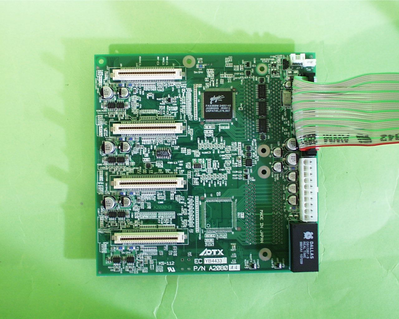
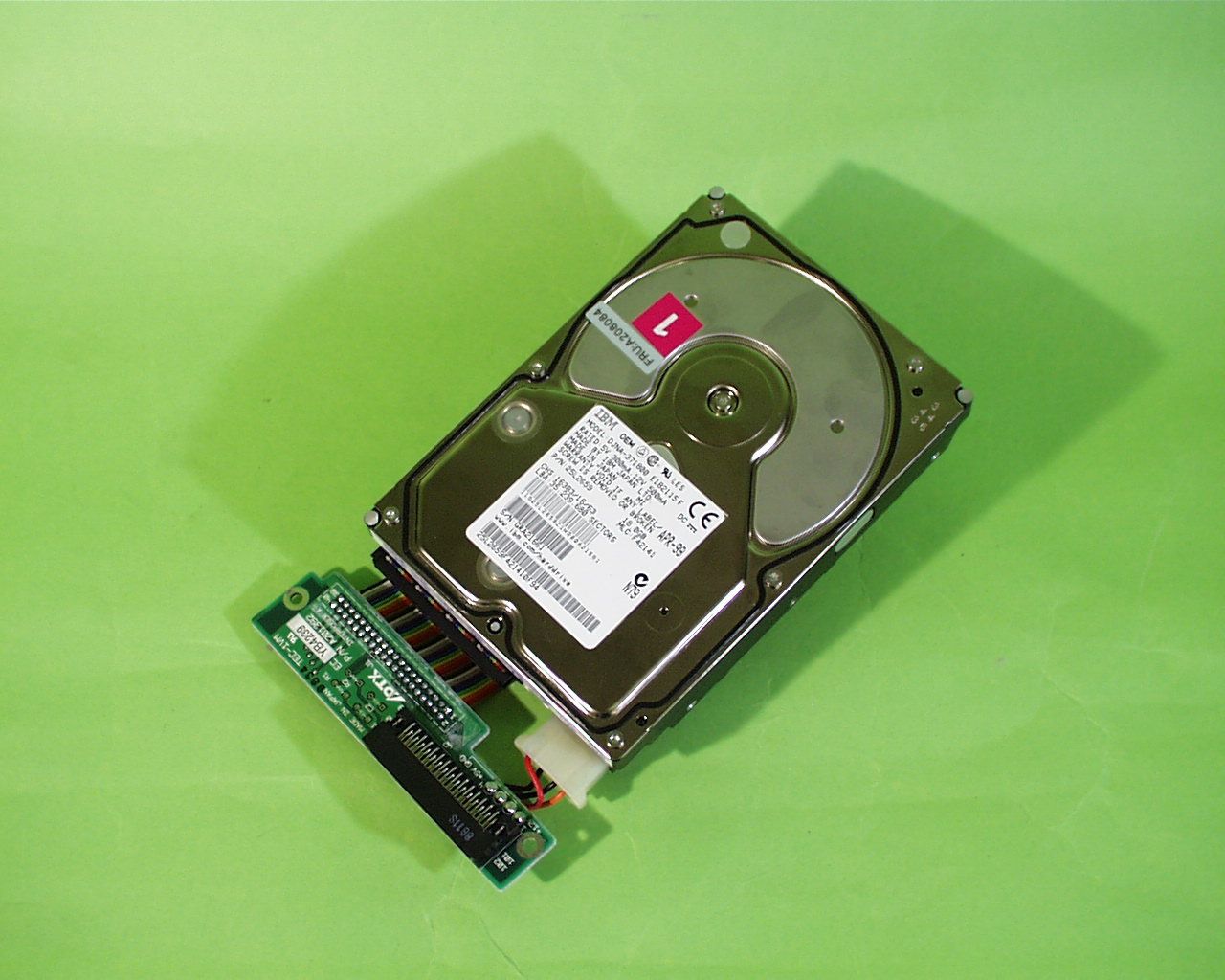
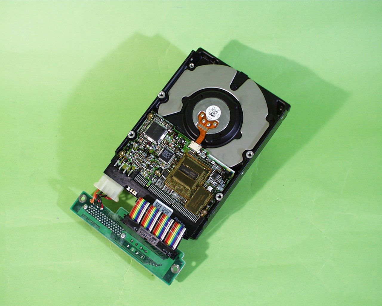
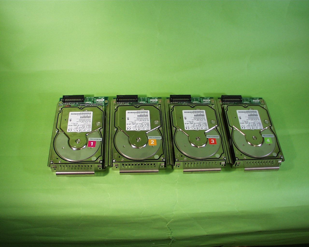
AXRS-JxxxS consists of a Controller Card, Power Supply, Fan, LED, LCD and Button Assembly and 4 Canisters with HDDs. The following block diagram shows the construction of AXRS-JxxxS. Gateway#1 generates oscillation of 20MHz and 40MHz. MPU, of 15MHz and 60MHz. Block Diagram Figure Block diagram of AXRS-JxxxS Copyright ADTX Co., Ltd 1999 LEDs Button SW UPS Power Supply LCD FAN RTC GATEARRAY #1 GATEARRAY #2 SCSI CHIP U-W SCSI SE/LVD HDD #1 HDD #2 HDD #3 HDD #4 MPU 16MB SDRAM 15MHz 20MHz 16 16 16 32 32 32 32 I/O SIGNALS I/O SIGNALS RS232C xtal U-W SCSI SE/LVD Auto-ON/OFF Circuit TERMPWR POWER SUPPLY 3.3V 5V 12V 100-240VAC 5VSB FLASHROM 40MHz CKIO 60MHz OSC
Test Report
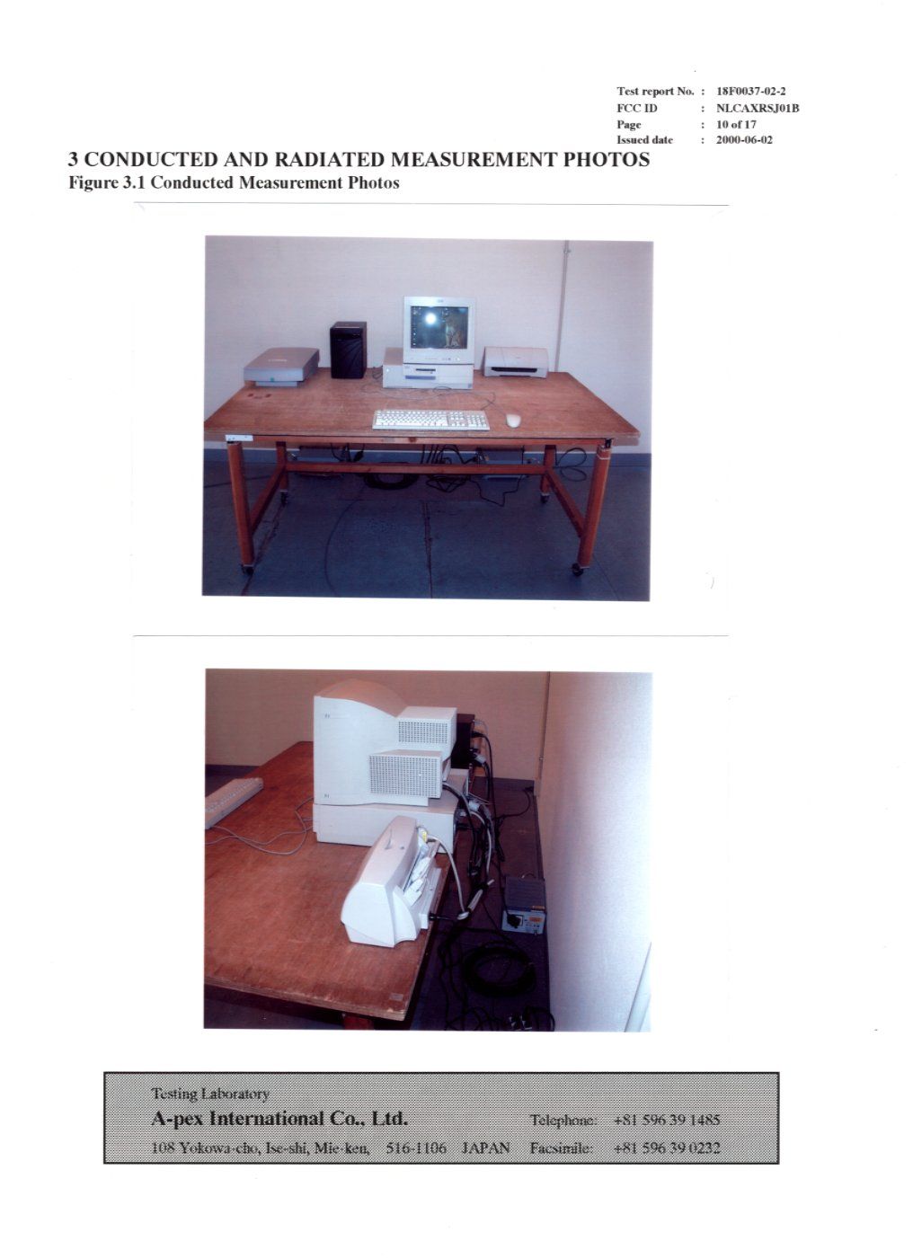
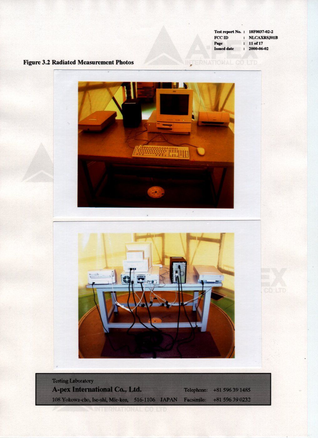
Test report No.: 18F0037-02-2 FCC ID : NLCAXRSJ01B Page: 2 of 17 Issued date: 2000-06-02 Testing Laboratory A-pex International Co., Ltd.Telephone:+81 596 39 1485 108 Yokowa-cho, Ise-shi, Mie-ken, 516-1106 JAPANFacsimile:+81 596 39 0232 Table of Contents Page 1 GENERAL INFORMATION3 1.1 Product Description4 1.2 Tested System Details5 1.3 Tested Methodology6 1.4 Test Facility6 2 SYSTEM TEST CONFIGURATION7 2.1Operation Environment 7 2.2 Justification7 2.3 EUT Exercise Software7 2.4 Test Procedure8 Figure 2.1 Configuration of Tested System9 3 CONDUCTED AND RADIATED MEASUREMENT PHOTOS10 Figure 3.1 Conducted Measurement Photos10 Figure 3.2 Radiated Measurement Photos11 3.1 Measurement Uncertainty12 4 CONDUCTED EMISSION DATA13 5 RADIATED EMISSION DATA14 5.1 Field Strength Calculation15 6 TEST EQUIPMENT USED16 APPENDIX17 A: Test DataA1 – A6 Test report No.: 18F0037-02-2 FCC ID : NLCAXRSJ01B Page: 3 of 17 Issued date: 2000-06-02 Testing Laboratory A-pex International Co., Ltd.Telephone:+81 596 39 1485 108 Yokowa-cho, Ise-shi, Mie-ken, 516-1106 JAPANFacsimile:+81 596 39 0232 1 GENERAL INFORMATION APPLICANT: ADVANCED TECHNOLOGY & SYSTEMS CO., LTD. Company Trade Name: ADTX ADDRESS: Yokohama Business Park, East Tower, 9F 134 Gohdo-cho, Hodogaya-ku, Yokohama-shi, Kanagawa-ken, Japan 240-0005 JAPAN Tel: +81-45-334-2179 Fax: +81-45-334-0094 REGULATION(S): FCC Part 15 Subpart B, Class B MODEL NUMBER: AXRS-JnnnS* n: 0 to 9 *: Blank or A to Z SERIAL NUMBER: - KIND OF EQUIPMENT: RAID Subsystem TESTED DATE: June 23, 25, 1999 RECEIPT DATE OF SAMPLE: June 22, 1999 TEST REPORT NUMBER: 18F0037-02-2 TEST SITE: A-PEX Yokowa No.2 Open Test Site Test report No.: 18F0037-02-2 FCC ID : NLCAXRSJ01B Page: 4 of 17 Issued date: 2000-06-02 Testing Laboratory A-pex International Co., Ltd.Telephone:+81 596 39 1485 108 Yokowa-cho, Ise-shi, Mie-ken, 516-1106 JAPANFacsimile:+81 596 39 0232 1.1 Product Description ADVANCED TECHNOLOGY & SYSTEMS CO., LTD., Model: AXRS-JnnnS* (referred to as the EUT in this report) is a RAID Subsystem. The clock frequency is 15MHz, 20MHz, 40MHz, 60MHz and 80MHz. Power Supply: AC 100-240V, 50/60Hz Test report No.: 18F0037-02-2 FCC ID : NLCAXRSJ01B Page: 5 of 17 Issued date: 2000-06-02 Testing Laboratory A-pex International Co., Ltd.Telephone:+81 596 39 1485 108 Yokowa-cho, Ise-shi, Mie-ken, 516-1106 JAPANFacsimile:+81 596 39 0232 1.2 Tested System Details The FCC IDs for all equipment, plus description of all cables used in the tested system are: Model DoC and FCC ID Description Cable description Backshell Material (1) ADTX NLCAXRSJ01BRAID SubsystemShielded SCSI CableP.V.C. M/N: AXRS-JnnnS*Unshielded AC Power CableP.V.C. (EUT) (2) IBMDoC Personal ComputerUnshielded RS232C CableP.V.C. M/N: PC300GL 6275-B9AUnshielded AC Power CableP.V.C. S/N: 68-2M89B (3) IBMH4ICM14018MonitorShielded Monitor CableP.V.C. M/N: 6540-02EUnshielded AC Power CableP.V.C. S/N: 66-R4737 (4) HPDoCScannerShielded USB CableP.V.C. M/N: Scan Jet5200CUnshielded AC Power CableP.V.C. S/N: SG933160XK (5) CanonDoCPrinterUnshielded Parallel CableP.V.C. M/N: BJF200Unshielded AC Power CableP.V.C. S/N: ETF52713 (6) IBMDoCKeyboardShielded Keyboard CableP.V.C. M/N: KB-7953 S/N: 0292004 (7) IBMDZL211029MouseUnshielded Mouse CableP.V.C. M/N: M-S34 S/N: 23-022637 Test report No.: 18F0037-02-2 FCC ID : NLCAXRSJ01B Page: 6 of 17 Issued date: 2000-06-02 Testing Laboratory A-pex International Co., Ltd.Telephone:+81 596 39 1485 108 Yokowa-cho, Ise-shi, Mie-ken, 516-1106 JAPANFacsimile:+81 596 39 0232 1.3 Tested Methodology Both conducted and radiated testing were performed according to the procedures in FCC/ANSI C63.4(1992). Radiated testing was performed at a distance of 3 meters from the antenna to EUT . 1.4 Test Facility The open area test site and conducted measurement facility used to collect the radiated data is located at 108, Yokowa-cho, Ise-shi, Mie-ken, 516-1106 Japan. This site has been fully described in a report dated May 27, 1997 submitted to FCC office, and accepted in a letter dated September 16, 1997 (31040/SIT 1300F2). Test report No.: 18F0037-02-2 FCC ID : NLCAXRSJ01B Page: 7 of 17 Issued date: 2000-06-02 Testing Laboratory A-pex International Co., Ltd.Telephone:+81 596 39 1485 108 Yokowa-cho, Ise-shi, Mie-ken, 516-1106 JAPANFacsimile:+81 596 39 0232 2 SYSTEM TEST CONFIGURATION 2.1 Operation Environment Conduction Radiation Temperature: 23 Degree: 25 Degree Humidity: 41%: 65% 2.2 Justification The system was configured in typical fashion (as a customer would normally use it) for testing. 2.3 EUT Exercise Software The EUT exercise program used during radiated testing was designed to exercise the various system components in a manner similar to typical use. The sequence is used: Operation: Running mode PC to EUT, EUT to PC DATA COPY Test report No.: 18F0037-02-2 FCC ID : NLCAXRSJ01B Page: 8 of 17 Issued date: 2000-06-02 Testing Laboratory A-pex International Co., Ltd.Telephone:+81 596 39 1485 108 Yokowa-cho, Ise-shi, Mie-ken, 516-1106 JAPANFacsimile:+81 596 39 0232 2.4 Test Procedure 2.4.1 Tabletop Equipment Conducted Emissions EUT was placed on a platform of nominal size, 1m by 1.5m, raised 80cm above the conducting ground plane. The rear of tabletop was located 40cm to the vertical conducting plane. The rear of EUT, including peripherals aligned and flush with rear of tabletop. All other surfaces of tabletop was at least 80cm from any other grounded conducting surface. I/O cables that were connected to the peripherals were bundled in center. They were folded back and forth forming a bundle 30cm to 40cm long and were hanged at a 40cm height to the ground plane. Each EUT current-carrying power lead, except the ground (safety) lead, were individually connected through a LISN to the input power source. All unused 50 ohm connectors of the LISN were resistively terminated in 50 ohm when not connected to the measuring equipment. 2.4.2 Tabletop Equipment Radiated Emissions EUT was placed on a platform of nominal size, 1m by 1.5m, raised 80…
Text truncated - open the document above for the full version.
Contact Information
Applicant
Yoshihiko Fujioka(Senior Manager)
045-334-0040Fax: 045-334-0094
Technical Contact
A-Pex International Co., Ltd.Kazutoyo Nakanishi
[email protected]+81-596-39-1485
108 Yokowa-cho · Ise-shi, Mie-ken · Japan
Non-Technical Contact
A-Pex International Co., Ltd.Momo Tsukamoto
[email protected]+81-596-39-1485
Test Firm
UL Japan, Inc.Kazunori Nishimura
Technical Specifications
| # | Rule Parts | Frequency Range | Power Output | Tolerance |
|---|---|---|---|---|
| 1 | 15B | - | - | ppm |
Other Applications from Advanced Technology and Systems Co Ltd
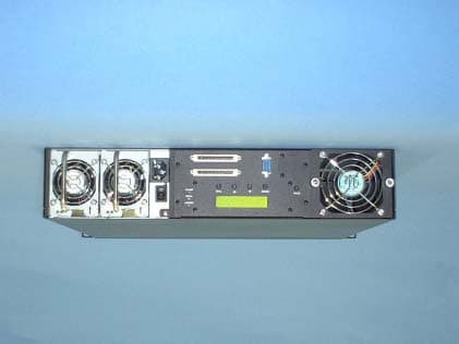
NLCAXRRK01D
Mar 10, 2002RAID Data Storage Computer
Equipment Class
JBC - Part 15 Class B Computing Device/Personal Computer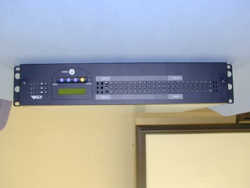
NLCAXRRJ01B
Feb 07, 2001RAID Redundent Mass Storage Device
Equipment Class
JBP - Part 15 Class B Computing Device PeripheralNLCAXRSF01A
Oct 08, 1997JBP - Part 15 Class B Computing Device Peripheral
Equipment Class
JBP - Part 15 Class B Computing Device Peripheral