NM483AQCT01Remote Garage Door/Gate Opener
AllStar Pro, LLC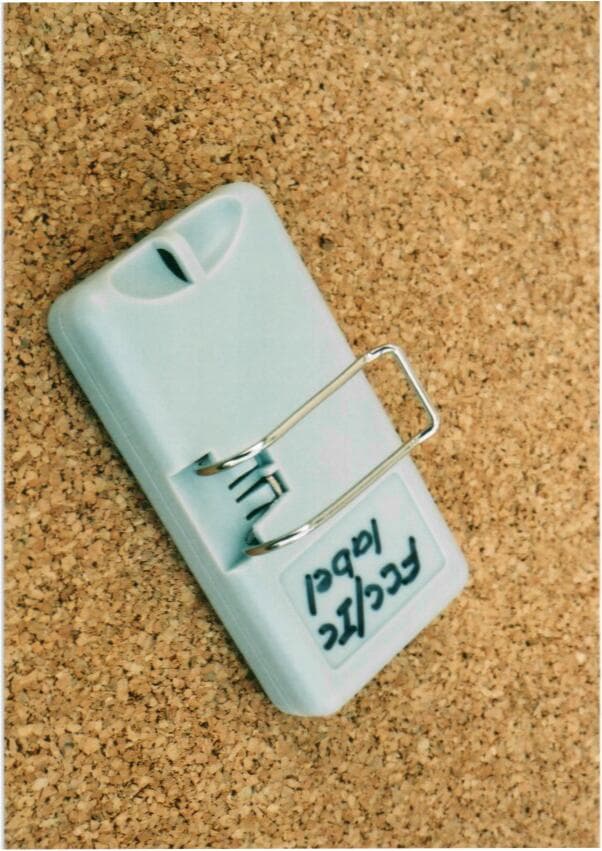
Click to zoom
Application Details
- Equipment Class
- DSC - Part 15 Security/Remote Control Transmitter
- Date of Grant
- Jul 29, 2002
- Application Purpose
- Original Equipment
- Date of Application
- Jul 29, 2002
- Equipment Note
- Remote Garage Door/Gate Opener
- Frequency Range
- 318.00000000 - 318.00000000
- Company
- AllStar Pro, LLC
- Country
- United States
Documents & Files
Document Text
Text extracted from the exhibit documents filed with the FCC. Open a document above to read the original.
Users Manual
Re: Certification for Allstar 110925 Transmitter Model: 110925 FCC ID: NM483AQCT01 IC: 4369A-83AQCT01 USER'S MANUAL INFORMATION (PRELIMINARY) The User's Manual is in preparation. The following material will be contained in the manual: FCC ID: NM483AQCT01 IC: 4369A-83AQCT01 This device complies with Part 15 of the FCC Rules and with RSS-210 of Industry Canada. Operation is subject to the following two conditions: (1) This device may not cause harmful interference, and (2) This device must accept any interference received, including interference that may cause undesired operation. WARNING: Changes or modifications not expressively approved by the party responsible for compliance could void the user's authority to operate the equipment. The term “IC:” before the radio certification number only signifies that Industry Canada technical specifications were met. Manufacturer’s Limited Warranty Allstar warrants its radio controls to be free from defect in material and workmanship for a period of one (1) year from the date of purchase. To obtain service, contact your dealer. To obtain service under this warranty the buyer must obtain authorization instructions for the return of any goods from Allstar before returning the goods. The goods must be returned with complete identification, with copy of proof-of-purchase, freight prepaid and in accordance with Allstar’s instructions or they will not be accepted. In no event will Allstar be responsible for goods returned without proper authorization or identification. Goods returned to Allstar for warranty repair within the warranty period, which upon receipt by Allstar are confirmed to be defective and covered by this limited warranty, will be repaired or replaced at Allstar’s sole option, at no cost and returned pre-paid. Defective parts will be repaired or replaced with new or factory rebuilt parts at Allstar’s sole option. This limited warranty does not cover non-defect damage, damage caused by unreasonable use, damage caused by improper installation or care, vandalism or lightning, fire or excessive heat, flood or other acts of God (including, but not limited to misuse, abuse or alterations, failure to provide reasonable and necessary maintenance), labor charges for dismantling or reinstalling a repaired or replaced unit, or replacement batteries. These warranties are in lieu of all other warranties, either expressed or implied. All implied warranties of merchantability and/or fitness for a particular purpose are hereby disclaimed and excluded. Under no circumstances shall Allstar be liable for consequential, incidental or special damages arising in connection with the use or inability to use this product. In no event shall Allstar’s liability for breach of warranty, breach of contract, negligence or strict liability exceed the cost of the product covered hereby. No person is authorized to assume for Allstar any other liability in connection with the sale of this product. This warranty gives you specific legal rights. You may also have other rights which vary from state to state. Warranty effective after May1, 2002. Operational Check After installing your receiver and transmitter, check the operation of your radio controls by moving approximately 45 feet back from the garage door, then press the transmitter button. Operation at this distance should be reliable. However, environmental conditions and the location of the transmitter and receiver will affect distance. • If the transmitter doesn’t activate the operator check the coding on both the transmitter and receiver. The code setting must match exactly . • If the distance is inadequate check the battery and replace if necessary. • To maximize the operating distance move the transmitter to different locations in the car until a satisfactory distance is achieved. Vanity mirrors on sun visors will affect performance. • If the receiver is in the proximity of a metal beam or other obstruction it may be necessary to relocate the receiver to increase the operating range. • If multiple receivers are mounted closer than 15 feet, blocking and interference may occur. Move the receivers farther apart. • If system does not work at any distance, check that the receiver terminals are connected to the proper operator terminals. • If the HomeLink® transmitter does not activate the operator or distance is inadequate,verify proper operation using the hand-held transmitter. Contact your HomeLink® system provider for help with configuring the HomeLink® transmitter and to resolve distance problems when using the HomeLink® system. Copyright © 2002 c.p.Allstar Corporation PART NUMBER 110977 REV A Allstar MVP Quik-CodeTransmitters and Receivers are compatible with HomeLink®. Radio Control Compatibility In addition to the Allstar MVP Residential Garage Door Operator, the MVP Quick-Code transmitter is designed to be compatible with all Allstar and Pulsar radio controls and includes models 9921T, 9921R, 9931T, 9931R, 8822T, 8822R, 8832T, 8832R, 8833T and 8833R. The Quik-Code transmitter is also compatible with many other brands of transmitters and receivers and operators. Consult the factory for a complete list. Your new radio controls are designed to remotely operate garage door and gate openers. The transmitter permits the user to select one of 19683 possible codes for each one of the three buttons. The radio frequency of the remote controls is fixed and tuned at the factory; adjustments are not required and should not be attempted by the end user. The MVP Quik-Code transmitter is based on the latest technology and provides maximum performance and maximum flexibility. Since each button of the Quik-Code transmitter may be programmed with a unique code, it is possible to control a single operator or a group of operators at one location or at multiple locations. The Quik-Code transmitter may be mounted on a visor using the metal visor clip (included) or attached to a key-chain with the built-in attachment. WARNING Keep transmi…
Text truncated - open the document above for the full version.
Cover Letter(s)
Re: Certification for Allstar 110925 Transmitter Model: 110925 FCC ID: NM483AQCT01 IC: 4369A-83AQCT01 POWER OF ATTORNEY A letter granting Valdis V. Liepa the Power of Attorney is on file and can be provided when so requested. Re: Certification for Allstar 110925 Transmitter Model: 110925 FCC ID: NM483AQCT01 IC: 4369A-83AQCT01 REQUEST FOR CONFIDENTIALITY Pursuant to 47 CRF 0.459, Allstar requests that a part of the subject application be held confidential. This comprises Exhibits (5) Schematics (10) Parts List (Part of Exhibit only) Allstar has spent substantial effort in developing this product and it is one of the first of its kind in industry. Having the subject information easily available to "competition" would negate the advantage they have achieved by developing this product. Not protecting the details of the design will result in financial hardship. If there are any questions regarding this request, please contact me at the above address or call 734-483-4211, fax 734-647-2106 or e-mail [email protected]. Sincerely, Valdis V. Liepa Research Scientist University of Michigan Re: Certification for Allstar 110925 Transmitter Model: 110925 FCC ID: NM483AQCT01 IC: 4369A-83AQCT01 GENERAL PRODUCT INFORMATION The device, for which certification is pursued, has been designed by: Allstar Corporation 4369A-83AQCT01 PO Box 240 Downingtown, PA 19335 David Guthrie Tel: 610-873-6900 Fax: 610-873-6958 It will be manufactured by: Allstar Corporation PO Box 240 Downingtown, PA 19335 David Guthrie Tel: 610-873-6900 Fax: 610-873-6958 Canadian Contact: Valmart Co., #114-9644 192nd St Surrey, BC, Canada V4N 4C6
Cover Letter(s)
July 29, 2002 American Telecommunications Certification Body 6731 Whittier Ave. McLean VA, 22101 RE: Comments for FCC ID: NM483AQCT01 1) Please comment on the optional parts in the schematic. It appears from the internal photographs that these were not present. Please note that the grant for this application will only be authorized for the transmitter as submitted. The schematic submitted demonstrates the correct layout for the DUT. However, the values of components within the schematics are not for the DUT (a up-to-date schematic for the components used was not available). It is the understanding of our test lab that the values listed in the Parts List are the correct values, and indicate that no components are to be placed in the optional areas. 2) The EUT appears to contain a metal visor clip (see external photographs) but it is not clear if this clip was present during final testing (see test photos). Please note that we have seen some of these transmitter where removing the clip can cause changes in the fundamental and harmonics. These changes are not consistent as one may increase while the other decreases. If the transmitter may be used with and without the clip, it should be checked both ways at both the fundamental and various harmonics. Please provided additional information to support which would be worse case (i.e. prescan data, or additional test data at fundamental, 4th, and 6th harmonic). The DUT will be sold with the metal clip attached and all testing was performed with the metal clip in place (see close-up of test-setup photos – clip is below, into the OATS table). The DUT is not to be sold or used without the metal clip. External Photos mistakenly left out the clip. 3) The Users Manual (page 4 of 5) shows the FCC logo. Please note that use of the FCC logo implies that a device that has been authorized with a Part 15 DoC approval which is not applicable to this device. Please remove this logo from the users manual. This has been corrected. The receiver for this transmitter does have DoC certification, and the symbol was placed in the user’s manual for that reason. See updated user’s manual. 4) Page 3 of the test report states the product is identified as a receiver?! Test report has been updated, thanks for catching that.
Cover Letter(s)
July 30, 2002 American Telecommunications Certification Body 6731 Whittier Ave. McLean VA, 22101 RE: Comments for FCC ID: NM483AQCT01 1) The test report (page 3) states that modifications were made to bring the DUT into compliance and that the changes are correctly represented in the Schematics and Parts List. However you last comment stated that the values of components within the schematic are not for the DUT. Please provide updated schematic(s) that reflects the final EUT as tested (including any modifications necessary to meet compliance). Our apologies. The NM483AQCT01 schematics and parts list are correct as submitted, we had a bit of confusion between this device and a different transmitter. The optional components listed in the schematic and parts list will not be used. 2) Your last response stated that The DUT will be sold with the metal clip attached and all testing was performed with the metal clip in place. However the photographs and manual support the fact that the clip may be removed for use as a keychain transmitter. The device should show compliance for all intended applications. Please note that we have seen some keychain/visor transmitters whose emissions dramatically change with removable of their metal clips. Therefore, please provide one of the following: a) Information showing that the clip is not designed to be removable, or b) Prescan information that supports the metal clip option is worse case for the fundamental, 4th, and 6th harmonics, or c) Additional final data for the fundamental, 4th, and 6th harmonics. See the second revision of the test report. The DUT has been tested at the worst case emissions for the following three configurations: 1) DUT with visor clip, 2) DUT with keychain ring, 3) DUT alone. The measurements made for DUT alone and DUT with keychain ring were indistinguishable (within 0.1 dB measurement uncertainty).
Cover Letter(s)
American Telecommunications Certification Body Inc. 6731 Whittier Ave, McLean, VA 22101 July 26, 2002 RE: Allstar Corporation FCC ID: NM483AQCT01 After a review of the submitted information, I have a few comments on the above referenced Application. 1) Please comment on the optional parts in the schematic. It appears from the internal photographs that these were not present. Please note that the grant for this application will only be authorized for the transmitter as submitted. 2) The EUT appears to contain a metal visor clip (see external photographs) but it is not clear if this clip was present during final testing (see test photos). Please note that we have seen some of these transmitter where removing the clip can cause changes in the fundamental and harmonics. These changes are not consistent as one may increase while the other decreases. If the transmitter may be used with and without the clip, it should be checked both ways at both the fundamental and various harmonics. Please provided additional information to support which would be worse case (i.e. prescan data, or additional test data at fundamental, 4 th , and 6 th harmonic). 3) The Users Manual (page 4 of 5) shows the FCC logo. Please note that use of the FCC logo implies that a device that has been authorized with a Part 15 DoC approval which is not applicable to this device. Please remove this logo from the users manual. 4) Page 3 of the test report states the product is identified as a receiver?! Timothy R. Johnson Examining Engineer mailto: [email protected] The items indicated above must be submitted before processing can continue on the above referenced application. Failure to provide the requested information may result in application termination. Correspondence should be considered part of the permanent submission and may be viewed from the Internet after a Grant of Equipment Authorization is issued. Please do not respond to this correspondence using the email reply button. In order for your response to be processed expeditiously, you must submit your documents through the AmericanTCB.com website. Also, please note that partial responses increase processing time and should not be submitted. Any questions about the content of this correspondence should be directed to the sender.
Cover Letter(s)
American Telecommunications Certification Body Inc. 6731 Whittier Ave, McLean, VA 22101 July 29, 2002 RE: Allstar Corporation FCC ID: NM483AQCT01 After a review of the submitted information, I have a few comments on the above referenced Application. 1) The test report (page 3) states that modifications were made to bring the DUT into compliance and that the changes are correctly represented in the Schematics and Parts List. However you last comment stated that the values of components within the schematic are not for the DUT. Please provide updated schematic(s) that reflects the final EUT as tested (including any modifications necessary to meet compliance). 2) Your last response stated that The DUT will be sold with the metal clip attached and all testing was performed with the metal clip in place. However the photographs and manual support the fact that the clip may be removed for use as a keychain transmitter. The device should show compliance for all intended applications. Please note that we have seen some keychain/visor transmitters whose emissions dramatically change with removable of their metal clips. Therefore, please provide one of the following: a) Information showing that the clip is not designed to be removable, or b) Prescan information that supports the metal clip option is worse case for the fundamental, 4 th , and 6 th harmonics, or c) Additional final data for the fundamental, 4 th , and 6 th harmonics. Timothy R. Johnson Examining Engineer mailto: [email protected] The items indicated above must be submitted before processing can continue on the above referenced application. Failure to provide the requested information may result in application termination. Correspondence should be considered part of the permanent submission and may be viewed from the Internet after a Grant of Equipment Authorization is issued. Please do not respond to this correspondence using the email reply button. In order for your response to be processed expeditiously, you must submit your documents through the AmericanTCB.com website. Also, please note that partial responses increase processing time and should not be submitted. Any questions about the content of this correspondence should be directed to the sender.
ID Label/Location Info
FULLSIZEARTWORK MVPTRANSMITTERFCCLABEL 1068-17-01_CUSEDON110925 BACKGROUNDCOLOR-PANTONE421M TEXTCOLOR-BLACK CPALLSTARCORPORATION MADEINCHINA MMYYX MODEL:110925 FCCID:NM483AQCT01 FREQ.318 IC:4369A-83AQCT01 THISDEVICECOMPLIESWITHF.C.C.RULESPART15 OPERATIONOFTHISDEVICEISSUBJECTTOTHE FOLLOWINGTWOCONDITIONS,(1)THISDEVICEMAY NOTCAUSEHARMFULINTERFERENCE,(2)THISDEVICE MUSTACCEPTANYINTERFERENCETHATMAYCAUSE UNDESIREDOPERATION
Operational Description
Martec Access Products Inc. Confidential Page 1 of 1 Project: Allstar MVP Transmitter Document #: 1068-2 Doc Desc: Operation Description Rev: A Revision Date: 04/26/2002 1 Purpose This document describes how the user will program door codes into the MVP three- button transmitter. It also describes feedback that the transmitter gives to the user. 2 Programming Specification The user needs to program up to three different 9-‘bit’ codes into the transmitter. Each ‘bit’ can be one of three values – (“+”) button1, (“0”) button2, or (“-”) button3. Transmitter can be programmed to use only with new MVP systems. Each button on the transmitter can be programmed separately. 2.1 User Programming Sequence Programming is a three-step process: 1. To program button mode press “+“(most left) button then, while holding, activate “-” (most right) button Press one from outside buttons then press any other button. After 5 seconds period the LED will flash to indicate the start of programming. Release buttons during flashing. 2. Press the button you want to program. After pressing a button the LED goes on and stays on. 3. Press the 9-button sequence to program the 9-bits. Each button on the transmitter is labeled either +, 0, or –. Push the button for each bit representing the symbol for that position in the code. As each button is pushed the LED will goes off and come back on. After the entry of the final bit (#9) the LED will blink three times indicating that programming is complete, and the transmitter goes back to its normal mode. 2.2 Other Programming Notes If, at any time during programming, no button is pushed for 15 seconds, the transmitter will exit programming mode and turn the LED off. If button is pressed for 15 second the transmitter will exit programming mode and turn the LED off. Transmitter changes its code after full programming sequence. Martec Access Products Inc. Confidential Page 2 of 2 Anytime button (“+”) is programmed and the final bit (bit 9) is ‘+’ also, the software will automatically create codes for buttons 2 and 3, by using the first 8 bits of button one and appending a ‘0’ or ‘-‘ respectively. The transmitters will be initialized during manufacturing to an ‘unusable’ code that can be received by a specially designed tester but not by a field receiver.
Test Report
The University of Michigan Radiation Laboratory 3228 EECS Building Ann Arbor, MI 48109-2122 Tel: (734) 764-0500 Measured Radio Frequency Emissions From Allstar Transmitter Model: 110925 Report No. 415031-122 July 30, 2002 For: Allstar Corporation PO Box 240 Downingtown, PA 19335 Contact: David Guthrie Tel: 610-873-6900 Fax: 610-873-6958 PO: Verbal Tests supervised by: Measurements made by: Report approved by: _____________________ Valdis V. Liepa Valdis V. Liepa Joseph D. Brunett Research Scientist Summary Tests for compliance with FCC Regulations Part 15, Subpart C, and Industry Canada RSS-210, were performed on Allstar model 110925. This device is subject to the Rules and Regulations as a Transmitter. In testing completed on July 30, 2002, the device tested in the worst case met the allowed FCC specifications for radiated emissions by 1.0 dB (see p. 6). Besides harmonics, there were no other significant spurious emissions found; emissions from digital circuitry were negligible. The conducted emission tests do not apply, since the device is powered from two 3 VDC batteries. 2 1. Introduction Allstar model 110925 was tested for compliance with FCC Regulations, Part 15, adopted under Docket 87-389, April 18, 1989, and with Industry Canada RSS-210, Issue 5, November, 2001. The tests were performed at the University of Michigan Radiation Laboratory Willow Run Test Range following the procedures described in ANSI C63.4-1992 "Methods of Measurement of Radio-Noise Emissions from Low-Voltage Electrical and Electronic Equipment in the Range of 9 kHz to 40 GHz". The Site description and attenuation characteristics of the Open Site facility are on file with FCC Laboratory, Columbia, Maryland (FCC Reg. No: 91050) and with Industry Canada, Ottawa, ON (File Ref. No: IC 2057). 2. Test Procedure and Equipment Used The pertinent test equipment commonly used in our facility for measurements is listed in Table 2.1 below. The middle column identifies the specific equipment used in these tests. Table 2.1 Test Equipment. Test Instrument Eqpt. Used Manufacturer/Model Spectrum Analyzer (0.1-1500 MHz) Hewlett-Packard, 182T/8558B Spectrum Analyzer (9kHz-22GHz) X Hewlett-Packard 8593A SN: 3107A01358 Spectrum Analyzer (9kHz-26GHz) X Hewlett-Packard 8593E, SN: 3412A01131 Spectrum Analyzer (9kHz-26GHz) Hewlett-Packard 8563E, SN: 3310A01174 Spectrum Analyzer (9kHz-40GHz) Hewlett-Packard 8564E, SN: 3745A01031 Power Meter Hewlett-Packard, 432A Power Meter Anritsu, ML4803A/MP Harmonic Mixer (26-40 GHz) Hewlett-Packard 11970A, SN: 3003A08327 Harmonic Mixer (40-60 GHz) Hewlett-Packard 11970U, SN: 2332A00500 Harmonic Mixer (75-110 GHz) Hewlett-Packard 11970W, SN: 2521A00179 Harmonic Mixer (140-220 GHz) Pacific Millimeter Prod., GMA, SN: 26 S-Band Std. Gain Horn S/A, Model SGH-2.6 C-Band Std. Gain Horn University of Michigan, NRL design XN-Band Std. Gain Horn University of Michigan, NRL design X-Band Std. Gain Horn S/A, Model 12-8.2 X-band horn (8.2- 12.4 GHz) Narda 640 X-band horn (8.2- 12.4 GHz) Scientific Atlanta , 12-8.2, SN: 730 K-band horn (18-26.5 GHz) FXR, Inc., K638KF Ka-band horn (26.5-40 GHz) FXR, Inc., U638A U-band horn (40-60 GHz) Custom Microwave, HO19 W-band horn(75-110 GHz) Custom Microwave, HO10 G-band horn (140-220 GHz) Custom Microwave, HO5R Bicone Antenna (30-250 MHz) X University of Michigan, RLBC-1 Bicone Antenna (200-1000 MHz) X University of Michigan, RLBC-2 Dipole Antenna Set (30-1000 MHz) X University of Michigan, RLDP-1,-2,-3 Dipole Antenna Set (30-1000 MHz) EMCO 2131C, SN: 992 Active Rod Antenna (30 Hz-50 MHz) EMCO 3301B, SN: 3223 Active Loop Antenna (30 Hz-50 MHz) EMCO 6502, SN:2855 Ridge-horn Antenna (300-5000 MHz) X University of Michigan Amplifier (5-1000 MHz) X Avantak, A11-1, A25-1S Amplifier (5-4500 MHz) X Avantak Amplifier (4.5-13 GHz) Avantek, AFT-12665 Amplifier (6-16 GHz) Trek Amplifier (16-26 GHz) Avantek LISN Box University of Michigan Signal Generator Hewlett-Packard 8657B 3 3. Configuration and Identification of Device Under Test The DUT is a 318 MHz transmitter, 1.5 x 0.5 x 3.25 inches in size. It operates at 318 MHz and the carrier is amplitude modulated. The carrier is LC stabilized; the modulating frequency is stabilized within the IC. The antenna is fabricated into the PCB. The DUT was designed and manufactured by Allstar Corporation, PO Box 240, Downingtown, PA 19335. It is identified as: Allstar Corporation Transmitter Model: 110925 S/N or P/N: proto FCC ID: NM483AQCT01 IC: 4369A-83AQCT01 Since the transmitter transmits continuous as long as the button is depressed, only one transmitter was used in all of the measurements. The DUT has been tested with a visor clip, keychain ring, and stand- alone to verify the worst case emissions. Stand alone measurements were indistinguishable from those taken with the keychain ring. Note: The DUT is manually activated and ceases to transmit within 5 seconds of deactivation. See Figure 6.4. 3.1 Modifications Made Components in the RF section of the DUT were adjusted to bring the DUT into compliance. Those changes are correctly represented in the Schematics and Parts List included in this submittal. 4. Emission Limits The DUT tested falls under the category of an Intentional Radiators and the Digital Devices. For FCC, it is subject to Part 15, Subpart C, (Section 15.231), Subpart B, (Section 15.109), and Subpart A, (Section 15.33). For Industry Canada it is subject to RSS-210, (Sections 6.1 and 6.3). The applicable testing frequencies with corresponding emission limits are given in Tables 4.1 and 4.2 below. As a digital device, the DUT is considered as a Class B device. 4.1 Radiated Emission Limits Table 4.1. Radiated Emission Limits (FCC: 15.33, 15.35, 15.109; IC: RSS-210, 6.2.2(r)). (Digital Class B) Freq. (MHz) E lim (3m) μV/m E lim dB(μV/m) 30-88 100 40.0 88-216 150 43.5 216-960 200 46.0 960-2000 500 54.0 Note: Average readings apply above 1000 MHz (1 MHz BW) Quasi-Peak readings apply to 1000 MHz (120 kHz BW) 4 Table 4.2. Radiated Emiss…
Text truncated - open the document above for the full version.
Contact Information
Applicant
David C Guthrie
Technical Contact
University of Michigan/EECSValdis V Liepa
[email protected]734-483-4211
1301 Beal Ave. · Ann Arbor, Michigan · United States
Non-Technical Contact
University of Michigan/EECSValdis V Liepa
[email protected]734-483-4211
Test Firm
University of MichiganValdis Liepa
Technical Specifications
| # | Rule Parts | Frequency Range | Power Output |
|---|---|---|---|
| 1 | 15.231 | 318 MHz - 318 MHz | - |
Other Applications from AllStar Pro, LLC
NM483AQCT04
Feb 23, 2003Wireless Door Control Transmitter
Equipment Class
DSC - Part 15 Security/Remote Control Transmitter
NM483AQCT03
Feb 19, 2003Wireless Door Control Transmitter
Equipment Class
DSC - Part 15 Security/Remote Control Transmitter
NM483AQCT02
Jul 29, 2002Remote Garage Door/Gate Opener
Equipment Class
DSC - Part 15 Security/Remote Control TransmitterNM483PLRR
Feb 17, 1998CRR - Superregenerative Receiver
Equipment Class
CRR - Superregenerative ReceiverNM483PTRAF
Feb 17, 1998DSC - Part 15 Security/Remote Control Transmitter
Equipment Class
DSC - Part 15 Security/Remote Control Transmitter