NMEAVTS1000AVTS1000
Data Critical Corporation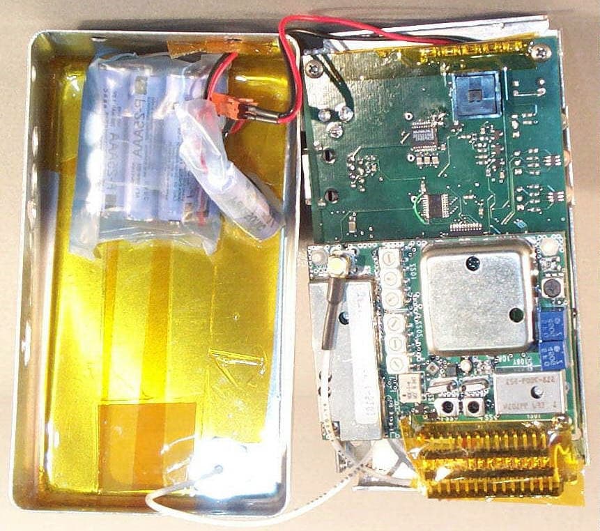
Click to zoom
Application Details
- Equipment Class
- TNB - Licensed Non-Broadcast Station Transmitter
- Date of Grant
- Sep 05, 2002
- Application Purpose
- Original Equipment
- Date of Application
- Jan 26, 2000
- Equipment Note
- AVTS1000
- Frequency Range
- 450.00000000 - 466.00000000
- Company
- Data Critical Corporation
- Country
- United States
Documents & Files
Document Text
Text extracted from the exhibit documents filed with the FCC. Open a document above to read the original.
Users Manual
EXHIBIT T – Service Manual FCC ID# NMEAVTS1000 AlarmView™ Service and Installation Manual Page 1 DATA CRITICAL CORP. AlarmView™ Service and Installation Manual AlarmView™ Service and Installation Manual Page 2 Precautionary Information Caution Instructions - For continued safe use of this equipment, it is necessary that the listed instructions be followed. However, instructions listed in this manual in no way supersede established medical procedures concerning patient care. Intended Use - The system is intended to monitor various patient-monitoring devices for alarm conditions, and responds by transmitting message data that includes text information from the patient. Confirmation - When the system sends out a page, there is NO confirmation back that the intended pager has successfully received the page. Maintenance - Failure on the part of the hospital or institution to maintain the equipment as outlined in this manual may cause pre-mature equipment failure. Installation - The AlarmView System has been installed by qualified technicians. Modification of this installation may cause undue equipment failure. Electromagnetic Interference - The AlarmView System may cause electromagnetic interference with devices operated in close proximity to the transmitter (refer to Appendix C). System Components - Do not spill liquids on any of the AlarmView™ System components. AlarmView™ Service and Installation Manual Page 3 Warnings Patient Monitoring - The most reliable method of patient monitoring combines close personal surveillance with correct operation of monitoring equipment. Patient alarm conditions and notifications are primary functions of the patient monitoring system. It is imperative that the caregiver and/or monitoring floor technicians monitor patient alarm conditions. The AlarmView System is not intended for use as the primary source for the patient alarm notification. Accidental Spills - In the event fluids are accidentally spilled in the equipment, take the equipment out of service and check for damage. Check operation after drying 24 hours later. Antenna Placement - The transmitter unit with a transmitter antenna may interfere with computer equipment with electronic switchboards located close to the antenna. If the transmitter unit must be located close to these types of equipment, a remote antenna should be used. Change of Performance - If the system fails to page users reliably, contact the hospital staff responsible for electromagnetic environment and Data Critical Corp. immediately. (Data Critical Corp. 24 hour support at 1-877-322-7828) Electrical Shock - To reduce the risk of electrical shock, DO NOT remove cover (or back). Refer servicing to qualified personnel. Environment - Data Critical Corporation does not assume responsibility for damage to the equipment caused by improperly vented cabinets, improper or faulty power, or insufficient wall strength to support equipment mounted on such walls. Explosion Hazard - Do not use this equipment in the presence of flammable anesthetics, skin cleaning agents, and disinfectants. Great care must be exercised when the device is used in an oxygen-enriched atmosphere. The atmosphere is considered to be oxygen enriched when the room air contains more than 25% of oxygen or nitrous oxide. ! AlarmView™ Service and Installation Manual Page 4 Home Use - AlarmView™ System is not intended for home use. Power - Convenience outlets and all others that may be used for the patient must be on the hospital emergency circuit so that they are energized at all times. Site Surveys - Each institution is responsible for surveying existing equipment and ensuring no conflict exists when considering the introduction of additional radiating devices. Transmission Bands - Each institution is responsible for maintaining continued surveillance of transmission bands being used in the facility to prevent co-occupation of bands and cross- band interference. Service and Technical Support Direct all inquires to: Data Critical Corporation 19820 North Creek Parkway Suite 100 Bothell, WA 98011 For technical advice or information concerning any equipment in your AlarmView™ System, contact Technical Support. Call, toll free at 1-877-DCC-STAT (1-877-322-7828). Copyright © 1998-1999 Data Critical Corp. All Rights Reserved. AlarmView™ Service and Installation Manual Page 5 Conventions of this Manual Two items that may help you as you work through the AlarmView User’s Guide are the special notes and cautions that appear throughout this text. Individual icons identify these notes and cautions, and they alert you to special information. The Caution icon alerts you to possible problems that you may encounter as you work through the AlarmView™ System programs. The possibility of losing data, for example, is information that could be mentioned in a caution. NOTE The Note icon alerts you to tips or hints that may make it easier for you to work within AlarmView System programs. These might include data entry tips, additional information about a window or field, or recommended procedures. NOTE: Due to continuing product innovation, specifications in this manual are subject to change without notice. Trademarks: Nellcor Puritan Bennett™ are registered trademarks of Nellcor Puritan Bennett, Inc. Windows™ CE is a registered trademark of Microsoft Corporation. AlarmView™ System is registered trademark of Data Critical Corporation. AlarmView™ Service and Installation Manual Page 6 Purpose The technical publications staff of Data Critical Corporation. prepared this service manual for the AlarmView system. This manual is geared for qualified service representatives and technical personnel involved in maintaining and repairing the AlarmView system. This manual is geared toward trained biomedical engineers. Users are expected to have a strong background in electronics, including a strong background in analog circuitry, digital circuitry, and microprocessor and microcontroller architecture. Safety In…
Text truncated - open the document above for the full version.
Users Manual
EXHIBIT U – User Manual FCC ID# NMEAVTS1000 DATA CRITICAL CORP. AlarmView™ Users Guide Document Precautionary Information Caution Instructions - For continued safe use of this equipment, it is necessary that the listed instructions be followed. However, instructions listed in this manual in no way supersede established medical procedures concerning patient care. Intended Use - The system is intended to monitor various patient- monitoring devices for alarm conditions, and responds by transmitting message data that includes text information from the patient. Confirmation - When the system sends out a page, there is NO confirmation back that the intended pager has successfully received the page. Maintenance - Failure on the part of the hospital or institution to maintain the equipment as outlined in this manual may cause pre-mature equipment failure. Installation - The AlarmView System has been installed by qualified technicians. Modification of this installation may cause undue equipment failure. Electromagnetic Interference - The AlarmView System may cause electromagnetic interference with devices operated in close proximity to the transmitter (refer to Appendix C). System Components - Do not spill liquids on any of the AlarmView™ System components. Warnings Patient Monitoring - The most reliable method of patient monitoring combines close personal surveillance with correct operation of monitoring equipment. Patient alarm conditions and notifications are primary functions of the patient monitoring system. It is imperative that the caregiver and/or monitoring floor technicians monitor patient alarm conditions. The AlarmView System is not intended for use as the primary source for the patient alarm notification. Accidental Spills - In the event fluids are accidentally spilled in the equipment, take the equipment out of service and check for damage. Check operation after drying 24 hours later. Antenna Placement - The transmitter unit with a transmitter antenna may interfere with computer equipment with electronic switchboards located close to the antenna. If the transmitter unit must be located close to these types of equipment, a remote antenna should be used. Change of Performance - If the system fails to page users reliably, contact the hospital staff responsible for electromagnetic environment and Data Critical Corp. immediately. (Data Critical Corp. 24 hour support at 1-877-322-7828) Electrical Shock - To reduce the risk of electrical shock, DO NOT remove cover (or back). Refer servicing to qualified personnel. ! Environment - Data Critical Corporation does not assume responsibility for damage to the equipment caused by improperly vented cabinets, improper or faulty power, or insufficient wall strength to support equipment mounted on such walls. Explosion Hazard - Do not use this equipment in the presence of flammable anesthetics, skin cleaning agents, and disinfectants. Great care must be exercised when the device is used in an oxygen-enriched atmosphere. The atmosphere is considered to be oxygen enriched when the room air contains more than 25% of oxygen or nitrous oxide. Home Use - AlarmView™ System is not intended for home use. Power - Convenience outlets and all others that may be used for the patient must be on the hospital emergency circuit so that they are energized at all times. Site Surveys - Each institution is responsible for surveying existing equipment and ensuring no conflict exists when considering the introduction of additional radiating devices. Transmission Bands - Each institution is responsible for maintaining continued surveillance of transmission bands being used in the facility to prevent co-occupation of bands and cross-band interference. Indications for Use This device is intended for use in real-time monitoring of routine patient status and alarm events on medical devices. It serves as a parallel, redundant mechanism to inform the clinical staff of patient events. It is intended to be a secondary means of annunciating and displaying patient alarm information to mobile healthcare providers. AlarmView is limited to use by qualified medical professionals who have been trained on the use of the device. It is intended for use in hospital and hospital type environments and is not for home use. AlarmView is intended to supplement and not to replace any part of the current device monitoring procedures. AlarmView is not considered in and of itself to be diagnostic without skilled interpretation and does not replace physician’s care. AlarmView is currently validated for use with the N-x9y and the N-3000 data protocols. Please note that we have demonstrated compatibility with the data protocols that Nellcor Puritan Bennett has defined, not the individual monitors. However, for FDA reference, the chart below indicates all models using the protocol. Data Critical is compatible with all the listed monitors. Protocol:All Current Models: N-x9yN-290, N-295 N-3000N-3000 For devices not listed in the above compatibility chart, a separation distance of 5.5 feet between the AlarmView Transmitter and other emitting devices should be observed. For the devices listed on the above compatibility chart, the AlarmView Transmitter may be placed in either of the configurations described below: • The AlarmView transmitter can be located remotely from the patient device (e.g. place the AlarmView Transmitter on the wall instead of the patient monitoring equipment). • When placing the AlarmView Transmitter in close proximity to the patient monitoring equipment, place it as shown in the drawing below, using the velcro attachment provided: Alarm Data The alarm data that the AlarmView system echoes are listed in the following chart. AlarmNx9yN3000 SPO2 Upper LimitXX SPO2 Lower LimitXX PR Upper LimitXX PR Lower LimitXX No Pulse MotionXX No Pulse No MotionXX Sensor DisconnectXX HR Upper LimitX HR Lower LimitX AsystoleX ECG Lead OffX ECG Cable OffX ECG Operations ErrorX ECG NoiseX RR Upper LimitX RR…
Text truncated - open the document above for the full version.
Cover Letter(s)
EXHIBIT S – Request for Confidentiality FCC ID# NMEAVTS1000 19820 NORTH CREEK PARKWAY, SUITE 100, BOTHELL, WA 98011 TEL 425.482.7000, FAX 425.482.7010, WEBSITE www.datacritical.com January 12, 2000 Federal Communications Commission Authorization and Evaluation Division 7435 Oakland Mills Road Columbia, Maryland 21046 Subject:Request for Confidentiality - FCC ID NMEAVTS1000 To whom it may concern, Data Critical Corporation hereby requests, pursuant to 47 CFR paragraph 0.459, that the following items which are submitted to the Commission as part of the application for the AVTS1000 be withheld from public inspection: 1. Schematics 2. Functional Block Diagrams 3. Theory of Operation Document 4. Bill Of Materials 5. AlarmView Human Factors Document We wish to withhold these items due to their content being privileged information. Disclosure of such information would be of substantial competitive harm and is confined to our authorized agents and our company. Thank you. Sincerely, Christopher Hartzog Quality Assurance Engineer Data Critical Corporation
Cover Letter(s)
Exhibits being submitted with the FCC application for the AlarmView AVTS1000 FCC ID NMEAVTS1000 Exhibit ATheory of Operations Exhibit BSchematics Exhibit CSchematics2 Exhibit DBill of Materials Exhibit ETransceiver Block Diagram Exhibit FSystem Block Diagram Exhibit GModulating Wavetrain Scope Exhibit HBode Plots Exhibit IRF Conducted Power Output Data Exhibit JOccupied Bandwidth Data Exhibit KVCO Schematic Exhibit LSpurious Emissions @ Antenna Terminals Data Exhibit MField Strength of Spurious Radiation Data Exhibit NFrequency Stability Data Exhibit OTransient Frequency Behavior Data Exhibit PCircuit Description Exhibit QTune-up Procedure Exhibit RAgent Authorization Letter Exhibit SRequest for Confidentiality Letter Exhibit TService Manual Exhibit UUser Guide Exhibit VTechnical Report Exhibit WFCC ID Label Exhibit XPhotos Enclosure/Antenna/Assembly Exhibit YPhotos RF Board Exhibit ZPhotos System Board Exhibit AAPhotos Power Supply
Cover Letter(s)
To:Application Examiner From: Greg Kiemel Date: 3/3/00 Re:FCC ID: NMEAVTS1000, EA 96615, DataCritical Corp. After uploading the exhibits for the subject application, I noticed two corrections that need to be made to the Form 731: Item #10 The equipment will be operated under FCC Rule(s): Part 90 Item#12 The necessary Bandwidth (per 2.202(b)) is 18K6, the Emission Designator is F1D, so the Emissions Designator column should read 18K6F1D. We initially e-mailed Betty Taube on Jan 31, 2000 with this information. Yesterday, she instructed me via e-mail to upload this letter via “ADD ATTACHMENTS” on the web site. Please let me know if we need to handle these corrections in a different way. Best regards, Greg Kiemel Northwest EMC, Inc. Ph (503) 844-4066 FAX (503) 844-3826 Email gkieme [email protected]
External Photos
EXHIBIT X – Photos – Enclosure/Antenna/Assembly FCC ID# NMEAVTS1000
External Photos
EXHIBIT AA – Photos – Power Supply FCC ID# NMEAVTS1000
ID Label/Location Info
EXHIBIT W – FCC ID Label FCC ID# NMEAVTS1000 FCC ID Label AlarmView Transmitter Data Critical Corporation Bothell, WA 98052, USA FCC ID: NMEAVTS1000 CANADA: XXXXXXXX Model: AVTS1000 Part Number: Location of FCC ID Label on EUT Bottom of Unit FCC ID NMEAVTS1000
Internal Photos
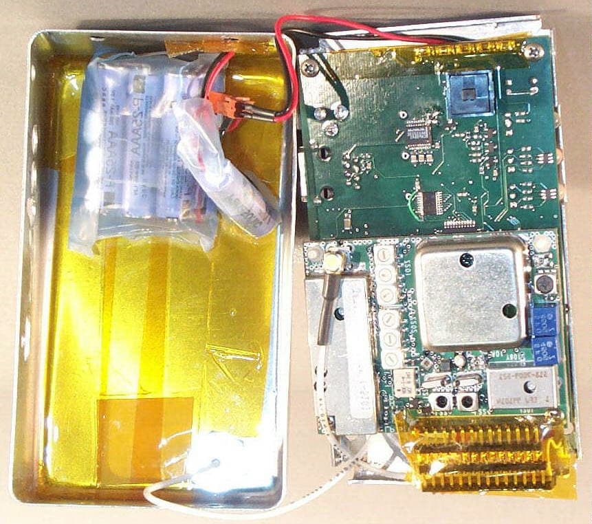
EXHIBIT Y – Photos – RF Board FCC ID# NMEAVTS1000
Internal Photos
EXHIBIT Z – Photos – System Board FCC ID# NMEAVTS1000
Test Report
EXHIBIT V – Technical Report FCC ID# NMEAVTS1000 Measurement/Technical Report Data Critical Corporation., AVTS1000 FCC ID: NMEAVTS1000 January 6, 2000 This report concerns (check one):Original Grant _x_ Class II Change_____ Equipment Type Licensed, Non-Broadcast Station Transmitter Deferred grant requested per 47 CFR 0.457 (d)(1)(ii)?yes_____ no__X__ If yes, defer until:______N/A______ date Data Critical Corporation agrees to notify the Commission by:______N/A______ date of the intended date of announcement of the product so that the grant can be issued on that date. Report prepared by:Northwest EMC, Inc. 22975 NW Evergreen Parkway, Suite 400 Hillsboro, OR 97124 (503) 844-4066 fax: (503) 844-3826 Report No. DATC0001 FCC ID: NMEAVTS1000 Northwest EMC, Inc.Report No. DATC0001Page - 2 Table of Contents SectionDescriptionPage 1.0General Information3 1.1Product Description3 1.2Related Submittals/Grants5 1.3Tested System Details5 1.4Test Methodology6 1.5Test Facility6 2.0Technical Description7 2.1Type of Emission7 2.2Frequency Range7 2.3Operating Power Level7 2.4DC Voltage and Current Applied7 2.5Schematics and Bill of Materials7 2.6Block Diagram7 2.7Circuit Description8 2.8Tune Up Procedure8 2.9Description of Modulation System8 Figure 2.1Configuration of Tested System9 3.0RF Conducted Power Output10 4.0Modulation Characteristics11 5.0Necessary Bandwidth12 6.0Occupied Bandwidth14 7.0Spurious Emissions at Antenna Terminals15 8.0Field Strength of Spurious Radiation16 9.0Frequency Stability19 10.0Transient Frequency Behavior20 11.0Measurement Equipment21 Appendix I Antenna Specifications22 FCC ID: NMEAVTS1000 Northwest EMC, Inc.Report No. DATC0001Page - 3 1.0 General Information 1.1 Product Description Manufactured By...................................................................................Data Critical Corporation. Address............................................19820 North Creek Parkway, Suite 100 Bothell, WA 98011 Test Requested By:.......................................................................................Christopher Hartzog Model...........................................................................................................................AVTS1000 FCC ID.................................................................................................................NMEAVTS1000 Applicable FCC Rule Part(s).........................................................................90.31, 90.22. 90.238 Serial Number(s).....................................................................................................................N/A Date of Test.............................................................December 16, 1999 through January 6, 2000 Job Number.................................................................................................................DATC0001 The Data Critical Corporation AlarmView AVTS1000 is a secondary alarm notification system that transmits alarm data from Primary Patient Monitoring Equipment (PME) to pagers that are worn by caregivers. The system consists of the following: • The AlarmView Pager – The AlarmView Pager is an off the shelf pager that is worn by caregivers responsible for individual patient care. • The AlarmView Programmer – The AlarmView Programmer is an off the shelf Personal Digital Assistant (PDA) with Windows CE operating system and equipped with AlarmView programming software. The PDA needs to have an infrared (IR) port to communicate with the transmitter. • The AlarmView Transmitter (EUT) – The AlarmView Transmitter is connected to the Patient Monitoring Equipment (PME) (i.e. Nellcor Puritan Bennett Pulse Oximeter – NPB-290, NPB-295, NPB-3000) with an AlarmView cable that is connected to the PME’s serial port. The transmitter is Data Critical Corporation’s proprietary RF transmitter operating in the UHF band (450-466MHz). It has a BNC connector for the antenna needed for the RF transmissions, an IR port used for setup, a button for power on/off and certain user initiated transmissions, and an RJ-45 connector for connection with the Patient Monitoring Equipment. The AVTS 1000 transmitter contains a Digital Processor Board and an off the shelf OEM transceiver module manufactured by Dataradio, Inc., Dataradio model DM-3474, part number 242-3474-510. The EUT is the AlarmView Transmitter. Please see the Theory of Operations, Exhibit “A”, file name: Theory_of_Operation.PDF FCC ID: NMEAVTS1000 Northwest EMC, Inc.Report No. DATC0001Page - 4 Hardware Description: • Clocks/Oscillators Frequencies:On the AlarmView Digital Processor PCB, there are crystal controlled clock oscillators of 48MHz and 18.432MHz. On the Dataradio DM-3474 transceiver module, there is a 17.5MHz voltage controlled TCXO and a VCO which operates from 450- 466 MHz in transmit and 502.95-518.95MHz in receive mode. In receive mode, the VCO output serves as the source for high side injection of the first receiver mixer. A second receive mixer and 450kHz 2 nd LO are contained in U241, the 2 nd IF and demodulator IC. • Ports:Data Port (for connection to Patient Monitor-not to a PC) • Antenna:Centurion Model EXC, ¼ wave helical flexible antenna (additional information may be referenced in Appendix I) • Frequency Range: 450-466MHz • Output Power:1 W • Modulation:POCSAG • Channel Bandwidth:25kHz • Channel Spacing:12.5kHz • Frequency Stability:1.5PPM • Data rate:2400bps • Emission Designator:F1D FCC ID: NMEAVTS1000 Northwest EMC, Inc.Report No. DATC0001Page - 5 1.2 Related Submittals/Grants None. 1.3 Tested System Details EUT and Peripherals ItemDescription and Serial No. EUTData Critical Corporation Model ATVS1000, FCC ID NMEAVTS1000. Patient MonitorNellcor Model NPB-295, Serial No. 21672473. Patient SimulatorNellcor Model SRC-2, Serial No. 21512643. Cables: Patient cable3.25 meters in length, shielding unknown, with ferrites. Data cable0.3 meters in length, shielded, no ferrites. Monitor power2.5 meters in length, unshielded, no ferrites. DC Power1.8 m…
Text truncated - open the document above for the full version.
Test Report
EXHIBIT G – Modulation Wavetrain Scope Plot FCC ID# NMEAVTS1000
Test Report
EXHIBIT H – Bode Plots FCC ID# NMEAVTS1000
Test Report
EXHIBIT I – RF Conducted Power Output Data FCC ID# NMEAVTS1000
Test Report
EXHIBIT I – RF Conducted Power Output Data FCC ID# NMEAVTS1000
Test Report
EXHIBIT J – Occupied Bandwidth Data FCC ID# NMEAVTS1000
Test Report
EXHIBIT L – Spurious Emissions at Antenna Terminals Data FCC ID# NMEAVTS1000
Test Report
EXHIBIT L – Spurious Emissions at Antenna Terminals Data FCC ID# NMEAVTS1000
Test Report
EXHIBIT L – Spurious Emissions at Antenna Terminals Data FCC ID# NMEAVTS1000
Test Report
EXHIBIT M – Field Strength of Spurious Radiation Data FCC ID# NMEAVTS1000 Rev 3.2 10/06/99 Comments: Frequency Meter ReadingDetector Antenna Factor Antenna PolarityPreamp GainCable Loss Table Azimuth Antenna Height Adjusted LevelSpec. LimitMargin (MHz)(dBuV)(dB/m)(dB)(dB)(degrees)(meters)(dBuV/m)(dBuV/m)(dB) 2302.50066.3PK30.0VHRN32.62.672.01.766.384.3-18.0 2302.50066.1AV30.0VHRN32.62.668.01.766.184.3-18.2 3684.00056.5PK33.2VHRN33.53.70.01.059.984.3-24.5 3684.00055.1AV33.2VHRN33.53.7161.01.158.584.3-25.8 1842.00057.2PK28.6HHRN33.02.4146.01.255.284.3-29.2 4144.50050.6PK33.7HHRN34.04.0147.01.054.384.3-30.1 1842.00056.2AV28.6HHRN33.02.4146.01.254.284.3-30.1 4605.00046.9PK35.0HHRN34.34.3203.01.151.984.3-32.5 4144.50047.7AV33.7HHRN34.04.0147.01.051.484.3-32.9 3223.50045.5PK32.6VHRN33.33.4121.01.048.284.3-36.2 2429.00047.8PK30.2HHRN33.32.6181.02.047.384.3-37.1 1943.00046.9PK29.0HHRN31.72.5162.01.046.784.3-37.6 4605.00040.6AV35.0HHRN34.34.3203.01.145.684.3-38.8 921.00050.3PK23.5VLPA32.01.7197.01.343.584.3-40.8 360.83057.8PK15.5HLPA31.31.0118.01.043.084.3-41.3 921.00049.8AV23.5VLPA32.01.7197.01.343.084.3-41.3 3223.50039.4AV32.6VHRN33.33.4121.01.042.184.3-42.3 2429.00041.5AV30.2HHRN33.32.6181.02.041.084.3-43.3 1943.00040.5AV29.0HHRN31.72.5162.01.040.384.3-44.0 360.83044.0AV15.5HLPA31.31.0118.01.029.284.3-55.1 12/20/99 Rod Peloquin, EV01 2145.0 Transmitting mid band. Antenna port terminated into dummy load. Alarm View Transmitter Data Critical Corporation DATC0001 Test Equipment Test System Temperature (°C):% Humidity: Customer Reference Number:Software:Power: FCC Part 90 Radiated Spurious Emissions (3m Limit) Northwest EMC, Inc., Radiated and Conducted Emissions Data Sheets EUT:Serial Number:Job Number:Date: Manufacturer:Test Engineer:Job Site: 0.0 10.0 20.0 30.0 40.0 50.0 60.0 70.0 80.0 90.0 100.0 10100100010000 Frequency (MHz) dBuV/meter
Test Report
EXHIBIT N – Frequency Stability Data FCC ID# NMEAVTS1000 Rev 3.2 10/06/99 Comments: Frequency Stability with Variation of Ambient Temperature (Primary Supply = 120V, 60Hz) Frequency Stability with Variation of Primary Supply Voltage (Ambient Temperature = 25 o C) 460.486570 5 460.486205 460.486205460.486550 460.486205460.486535 460.486205460.486520 460.486205460.486575 5 0.805 0.835 5 0.755 0.725 114 (95%) 108 (90%) 102 (85%) 0.79 0.68 0.83 460.486205460.486585 460.486205460.486585 138 (115%) 132 (110%) 126 (105%) 120 (100%) (VAC, 60Hz) ToleranceSpecification (ppm)(ppm) Assigned Frequency (MHz)(MHz) Measured Frequency 460.485900 460.486205 460.485725 Voltage Measured Frequency (MHz) 460.485655 460.485765 460.486205 460.486205 460.486205 460.486495 460.486765 460.486790 460.486205 460.486205 460.486205 460.486205 Assigned Frequency (MHz) 460.486205 460.486205 5 5 5 5 -0.96 5 5 5 1.27 Specification (ppm) 5 5 -0.66 0.00 0.63 1.22 -1.04 460.485660 Tolerance (ppm) 30 Temp ( o C) -30 -20-1.18 -1.19 40 50 -10 0 10 20 Northwest EMC, Inc., Frequency Stability Data Sheets EUT:Serial Number:Job Number:Date: Alarm View TransmitterDATC000112/21/99 Manufacturer:Test Engineer:Job Site: Data Critical CorporationGreg KiemelEV Temperature Chamber Customer Reference Number:Software:Power: 120V, 60Hz (nominal) Transmitting mid band. Temperature (°C):% Humidity: 2145.0 Rev 3.2 10/06/99 Comments: Frequency Stability with Variation of Battery Voltage (Ambient Temperature = 21 o C) Transmitting mid band. Temperature (°C):% Humidity: 2145.0 Customer Reference Number:Software:Power: 9.6 VDC (nominal) Manufacturer:Test Engineer:Job Site: Data Critical CorporationGreg KiemelEV07 Alarm View Transmitter5.25" PrototypeDATC000101/05/00 Northwest EMC, Inc., Frequency Stability Data Sheets EUT:Serial Number:Job Number:Date: 8.68 (end point)0.005 464.499249 464.499249 464.499249 464.499249 464.499249 464.499249 464.499249464.499249 Voltage (VDC) Tolerance 11.04 (115%) 10.56 (110%) 10.08 (105%) 9.6 (100%) 9.12 (95%) 8.64 (90%) Specification (ppm)(ppm) Assigned Frequency (MHz)(MHz) Measured Frequency 8.16 (85%) 0.04 0.00 0.02 464.499257 464.499259 0.02 464.499249 464.499267 5 5 0.005 5 464.499249 464.499264 464.499264 464.499249 5 5 0.035 0.03
Test Report
EXHIBIT O – Transient Frequency Behavior Data FCC ID# NMEAVTS1000 Transient Frequency Behavior Reference 90.214 Transmit Frequency: 464.5 MHz Output Power: 1 W Channel Bandwidth: 25kHz Modulation: POCSAG (typical of normal operation) Data Rate: 2400 b.p.s (maximum) Carrier ON Time Carrier OFF Time
Contact Information
Applicant
Sharon Untz
Technical Contact
Northwest EMC, Inc.Gregory V Kiemel
[email protected](503)844-4066
22975 NW Evergreen Parkway · Hillsboro, Oregon · United States
Non-Technical Contact
Northwest EMC, Inc.Liana Potter
[email protected](503)844-4066
Test Firm
Northwest EMC, Inc.Greg Kiemel
Technical Specifications
| # | Rule Parts | Frequency Range | Power Output | Emission | Tolerance |
|---|---|---|---|---|---|
| 1 | 90.203(j)(7) | 450 MHz - 466 MHz | 1 W | 18K6F1D | 1.5000000000 ppm |
Other Applications from Data Critical Corporation
NMEAVTS1010
Sep 05, 2002AVTS1010
Equipment Class
TNB - Licensed Non-Broadcast Station Transmitter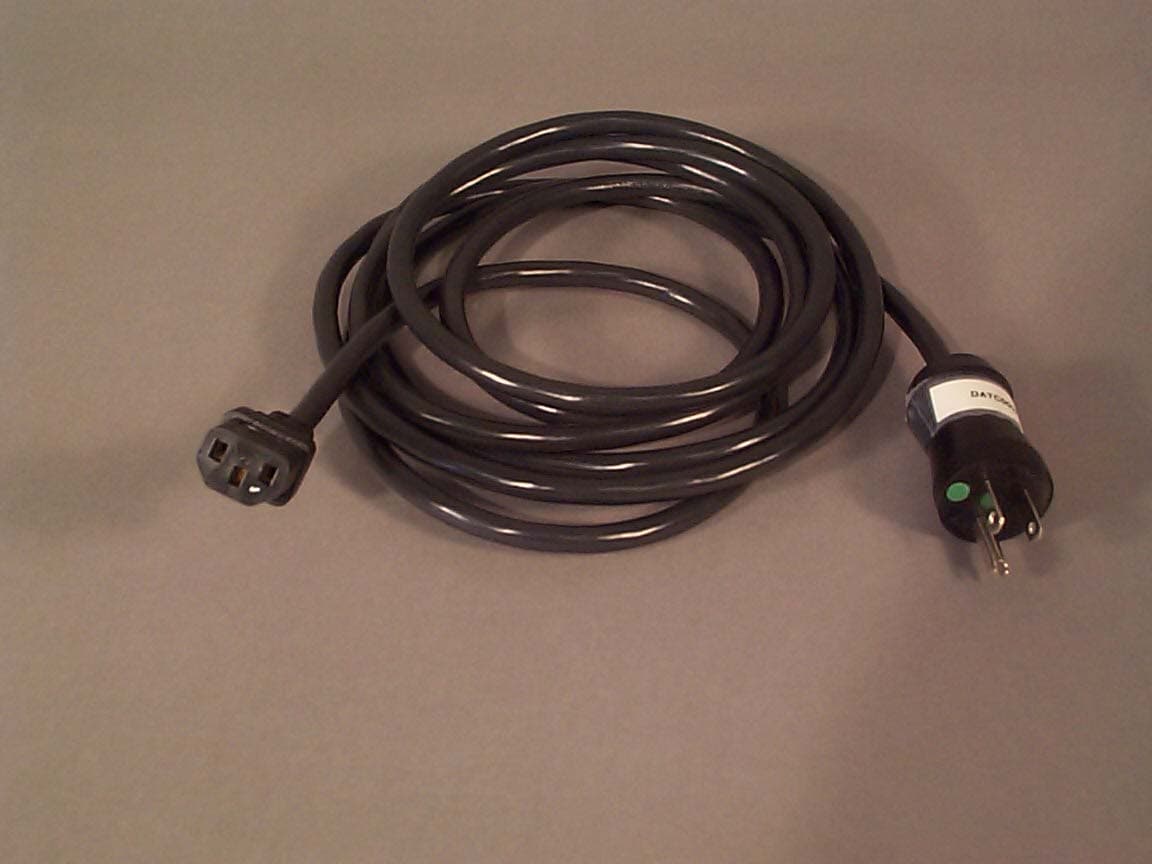
NMEAVTS1030
Jul 23, 2001Model AVTS1030, Rule Part 90.203(j)(7)
Equipment Class
TNB - Licensed Non-Broadcast Station TransmitterNME70000011
Nov 11, 1997Paging Receiver
Equipment Class
CXX - Communications Rcvr for use w/ licensed Tx and CBs