NP4-242-5099-100Wireless Radiomodem
CalAmp Wireless Networks Corporation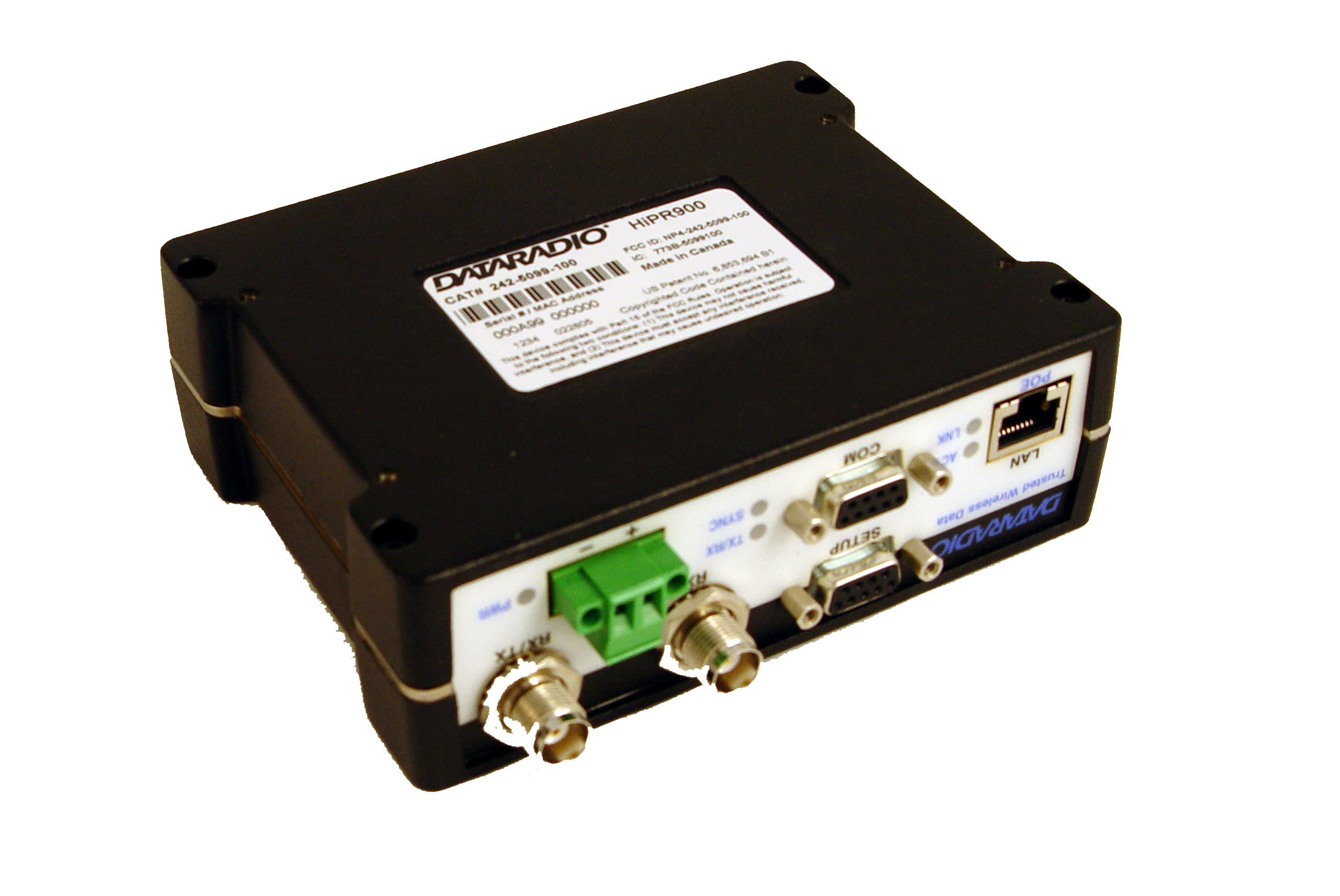
Click to zoom
Application Details
- Equipment Class
- DSS - Part 15 Spread Spectrum Transmitter
- Date of Grant
- May 08, 2005
- Application Purpose
- Original Equipment
- Date of Application
- May 08, 2005
- Equipment Note
- Wireless Radiomodem
- Frequency Range
- 902.50000000 - 927.50000000
- Country
- United States
Documents & Files
Document Text
Text extracted from the exhibit documents filed with the FCC. Open a document above to read the original.
Users Manual
HiPR-900™ Wireless Radiomodem User Manual Version 1.00 Preliminary The entire contents of this manual are copyright 2005 by DATARADIO Inc. ® Copyright DATARADIO Inc. February, 2005 Part no.: 120 40515-100a (FCC-2) Table of Contents 1. PRODUCT OVERVIEW.................................................................................................................................9 1.1 I NTENDED AUDIENCE......................................................................................................................................9 1.2 G ENERAL DESCRIPTION...................................................................................................................................9 1.2.1 Characteristics.....................................................................................................................................10 1.2.2 Accessories and Options......................................................................................................................10 1.2.3 Configuration.......................................................................................................................................11 1.3 F ACTORY TECHNICAL SUPPORT....................................................................................................................11 1.4 P RODUCT WARRANTY...................................................................................................................................11 1.5 R EPLACEMENT PARTS...................................................................................................................................11 1.5.1 Factory Repair.....................................................................................................................................11 1.6 U NPACKING...................................................................................................................................................12 2. INSTALLATION............................................................................................................................................13 2.1 P ARALLEL DECODE.......................................................................................................................................13 2.2 A NTENNAE INSTALLATION............................................................................................................................13 2.2.1 Professional Installation & RF Exposure Compliance Requirements.................................................13 2.2.2 Antenna Connection............................................................................................................................14 2.2.3 Spacing and Constraints......................................................................................................................14 2.2.4 Acceptable Antennae...........................................................................................................................15 2.3 N ETWORK APPLICATION................................................................................................................................ 15 2.3.1 Modes..................................................................................................................................................15 2.3.1.1 Bridge mode.................................................................................................................................................15 2.3.1.2 Router mode.................................................................................................................................................15 2.3.2 RF Path and communications range...................................................................................................16 2.3.3 COMMON CHARACTERISTICS........................................................................................................16 2.3.4 Basic connections................................................................................................................................16 2.3.5 POINT-TO-POINT SYSTEM...............................................................................................................16 POINT-MULTIPOINT SYSTEM.......................................................................................................................17 2.4 S ELECTABLE DATA RATES............................................................................................................................18 2.5 C OMBINED ACCESS POINT AND REMOTE.......................................................................................................18 2.6 O NLINE & OFFLINE DIAGNOSTICS.................................................................................................................18 2.7 B UILT-IN SPECTRUM ANALYZER...................................................................................................................18 3. PHYSICAL DESCRIPTION.........................................................................................................................19 3.1 F RONT PANEL................................................................................................................................................19 3.2 C ABLES AND CONNECTOR PIN-OUTS.............................................................................................................20 4. OPERATION & CONFIGURATION..........................................................................................................21 4.1 L OCAL AND REMOTE (OTA) CONFIGURATION..............................................................................................21 4.2 O VER-THE-AIR FIRMWARE UPGRADE...........................................................................................................21 4.3 B ROWSER-BASED SETUP AND STATUS..........................................................................................................21 4.3.1 LAN Setup........................…
Text truncated - open the document above for the full version.
Attestation Statements
Dataradio COR Ltd 299 Johnson Ave, Waseca MN 56093 Telephone: 507 833-6702 Facsimile 507 833-6748 May 6, 2005 RE: Dataradio HiPR-900 FCC ID: NP4-242-5099-100 AFFIDAVIT The finger stock grounding clip shown in the revised Internal Photos will be included in the manufacturing process and is needed to make the radiated spurious emission specifications. Mark Christensen Director of Product Development Dataradio COR Ltd
Cover Letter(s)
Dataradio COR Ltd. 299 Johnson Avenue – Suite 110 Waseca, MN 56093-0833 USA Phone: 507-833-8819 Fax: 507-833-6748 Request for Confidentiality Federal Communications Commission March 24, 2005 7435 Oakland Mills Road Columbia, MD 21046 We request the following information from our Certification application for the HiPR-900 be kept confidential pursuant to 47 CFR 0.459. The HiPR-900 is a Frequency Hopping Spread Spectrum transceiver operating under parts 15.247 and will be identified by FCC ID: NP4-242-5099-100 1) Circuit Schematics Attachment entitled: HiPR-900 rf schematic diagram.pdf Attachment entitled: HiPR-900 modem schematic diagram.pdf 2) Number of Hopping Frequencies Pseudorandom Frequency Hopping Sequence Equal Hopping Frequency Use / System Receiver Hopping Capability Time of Occupancy (Dwell Time) Attachment entitled: HiPR-900 hopping description.pdf 3) Bills of materials Attachment entitled: HiPR-900 bom.pdf 4) Block Diagrams Attachment entitled: HiPR-900 rf block diagram.pdf Attachment entitled: HiPR-900 modem block diagram.pdf This request is based on the fact that these are proprietary trade secrets of Dataradio. Dataradio does not make this information available to the public. Releasing this information gives competitors an unfair advantage of our proprietary research and development efforts. Sincerely, Mark Christensen Director of Product Development
Cover Letter(s)
American Telecommunications Certification Body Inc. 6731 Whittier Ave, McLean, VA 22101 March 31, 2005 RE: FCC ID: NP4-242-5099-100_ATCB002252 Attention: Mark A. Christensen I have a few comments on this Application. Please note that further comments may arise in response to answers provided to the questions below. 1. Please provide the required technical contact information on the 731 form. 2. Please note that the antenna terminals appear to be standard type connectors. 3. Please provide a sample of the FCC ID label. Please also note that the label shown in the external photos is not a proper FCC ID label. Please note that the FCC ID label must follow the required format as shown in 47CFR 2.926 and 2.925. This format as in the example shown Example: FCC ID: XXX123. Please note that the photo only shows “FCC NP4-242-5099-100” and is incorrect. It should be “FCC ID: NP4-242-5099-100”. As this is also an IC application, please provide a sample of the IC label. Please correct and provide the appropriate labels for the application. 4. Please provide a sample table showing the pseudo random nature of the hop sequence. Please note that the hop sequence is not only to be random in number but is to be equally random in forward hops channels but reverse hop channels as well (i.e. the hop channel selection should be equally + and – hops from the selected channel, etc). A sample of the hopping sequence shows this true random selection of channels. 5. Please provide the required test setup photos for part 15 devices. 6. Please note that the device appears to be more than sufficiently large to contain the 15.19(a)(3) (two condition) statement on the device itself. Please provide a sample label showing this two condition statement on the device. 7. Please provide a separate MPE calculation report. Please note that this is an FCC requirement. 8. Please note that DA000705 (the accepted FCC test procedure for FHSS devices) states that for channel separation measurements the resolution bandwidth must be equal to or greater than the span used. Please note that your test report shows that the resolution bandwidth used for this test was only 3 kHz and the span was 1MHz. While the channel separation appears to fully meet the criteria for FHSS devices in the 900MHz range, the test report does not follow acceptable procedures. Please explain and/or correct as necessary. 9. Please note that the 20dB bandwidth measurements are to be made where the resolution bandwidth is equal to or greater than 1% of the 20dB bandwidth. This means that for a device with a 20dB bandwidth of 488 kHz, the resolution bandwidth can b NO LESS than 4.8 kHz. Please note that your report states that a resolution bandwidth of 3 kHz was used. This means that the resolution bandwidth used is only approximately 0.6% or the 20dB bandwidth. Please note that the difference between the 3 kHz used and the minimum 4.8 kHz required could produce an error of approximately 2+dB in the readings. This 2+dB error, when projected as a correction factor onto the plots provided, may actually fail the maximum 500 kHz 20dB bandwidth limit. Consequently, because the device may actually fail the 500 kHz limit, the 20dB bandwidth measurement provided is not adequate to show compliance. Please re-measure the 20dB bandwidth using a resolution bandwidth EQUAL to or GREATER than 4.8 KHz. 10. Please note that on the radiated spurious emissions data tables on pages 29 through 31 are confusing and ambiguous. Please note that the tables on pages 29, 30, 34, 37 and 38 do not appear to give final result and do not actually appear to compare these readings to the limit. Please clearly explain the tables and show compliance to the limits. 11. Many of the data in the tables (see tables on page 31, 35 and 37) have no reference to units (i.e. what are they dBm, dBuV/m, dBc, dBW). Please note that the restricted band frequencies below 1GHz are QP limits of 54dBuv/m and the frequencies above 1GHz in the restricted bands have an average limit of 500uV/m (54dBuV/m) and a 20dB over the average limit of 5011uV/m (74dBuV/m). Please explain where you derived your limits in relation to the actual restricted band z Page 2 March 31, 2005 limits as shown in 15.209. Please clearly show compliance to the limits in the restricted bands as shown in 15.209 and 15.205. 12. Please note that page 39 of the report references ANSI C63.4 1992. Please note that this is not an acceptable reference as the FCC has stated that ANSI C63.4 2003 must be used. As there are significant differences between the two editions, please verify that the data is in compliance to ANSI C63.4 2003. 13. Please provide a completed RSP100 form for IC application 773A – 5099100. Dennis Ward mailto:[email protected] The items indicated above must be submitted before processing can continue on the above referenced application. Failure to provide the requested information may result in application termination. Correspondence should be considered part of the permanent submission and may be viewed from the Internet after a Grant of Equipment Authorization is issued. Please do not respond to this correspondence using the email reply button. In order for your response to be processed expeditiously, you must submit your documents through the AmericanTCB.com website. Also, please note that partial responses increase processing time and should not be submitted. Any questions about the content of this correspondence should be directed to the sender.
Cover Letter(s)
April 19, 2005 The following is the Dataradio COR Ltd. Response to ATCB comments on FCC ID: NP4- 242-5099-100_ATCB002252 dated March 31, 2005. 1. Form 731 completed and uploaded 2. Antenna connector are standard TNC connectors 3. FCC/IC label has been updated and reflect the proper FCC/IC format 4. Sample table of the hop sequence was added to the hopping description. 5. Photographs have been included to depict the test setup for Part 15 devices 6. Part 15.19(a)(3) has been incorporated into the FCC/IC/product label 7. A separate file containing MPE information is included 8. New plots were taken. 9. New plots and data were taken. 10. New data was taken and put into a more readable format. 11. Corrected with more readable tables. Used the limits of 15.209 for frequencies below 1 GHz and used 20 dB over the average limit (5000 μV/m) for frequencies above 1 GHz. 12. Data is in compliance to ANSI C63.4 2003. Reference new document in report. 13. RSP-100 has been completed and added to the list of existing documents.
RF Exposure Info
RF Exposure Compliance Requirements HiPR-900 FCC Rule: 1.1307, 1.1310, 2.1091(b)(d), 2.1093 IC Rule: RSS-210 (14), Exemption Clause RSS-102(4.3) Description of Compliance: The HiPR-900 is intended to be used in the SCADA (Supervisory Control And Data Acquisition) market and will be mounted with a fixed RTU (Remote Terminal Unit). The HiPR-900 will be professionally installed in such a way that a minimum separation distance of more than 20 cm will be maintained between the radiating structure and any person so it is classified as a mobile. A typical installation would be with the antenna mounted on a tower, in rare instances a ½ wave whip antenna would be used. In either installation the antenna would be mounted greater than the minimum distance calculated below. The calculation for the more stringent specification, a General Population/Uncontrolled Mobile device according to section 2.1091(b) and section 1.1310 Note 2 is shown below: Limits for General Population/Uncontrolled Exposure: Frequency Range (MHz) Electric Field Strength (V/m) Magnetic Field Strength (A/m) Power Density mW/cm 2 Averaging Time (minutes) 0.3-1.34 614 1.63 *(100) 30 1.34-30 824/f 2.19/f *(180/f2) 30 30-300 27.5 0.073 0.2 30 300-1500 --- --- f/1500 30 1500-100,000 --- --- 1.0 30 Environmental Specification: f (MHz) / 1500 mW/cm 2 f (902 MHz) / 1500 mW/cm 2 = .6 mW/cm 2 (worse case) S = (PG) / (4πR 2 ) (OET Bulletin 65) where: S = power density (in appropriate units, e.g. mW/cm 2 ) P = power input to the antenna (in appropriate units, e.g., mW) G = power gain of the antenna in the direction of interest relative to an isotropic radiator R = distance to the center of radiation of the antenna (appropriate units, e.g., cm) Distance Calculation: Maximum Antenna Gain: 8.5 dBi Yagi 10 (8.5dBi / 10) = 7.08 Power input to antenna: 27.5dBm = 10 (27.5dBm / 10) =562 mW .6 mW/cm 2 = (562mW * 7.08) / (4πR 2 ) Î Minimum Distance = 22.97 cm
Test Report
DATARADIO COR Ltd. Corporate Headquarters and Manufacturing Operations 299 Johnson Avenue, Suite 110 Waseca, MN 56093-0833 USA Phone: 507-833-8819 Fax: 507-833-6748 FCC Part 15.247 Certification Application for FCC ID: NP4-242-5099-100 Industry Canada RSS 210 Application Test Report And Technical Documentation For Dataradio COR Ltd. HiPR-900™ Frequency Hopping Wireless Modem DATARADIO COR Ltd. NP4-242-5099-100 FCC Part 15.247, Frequency Hopping Wireless Modem Page 2 of 38 AFFIDAVIT The technical data included in this report has been accumulated through tests that were performed by me or by engineers under my direction. To the best of my knowledge, all of the data is true and correct. Mark Christensen Director of Product Development, Dataradio COR Ltd. DATARADIO COR Ltd. NP4-242-5099-100 FCC Part 15.247, Frequency Hopping Wireless Modem Page 3 of 38 Table of Contents Section Title Page # Engineering Statement of Matt Schellin 4 1 Qualifications of Engineering Personnel 5 2 General Information 6 3 Test Facilities 7 4 Antenna Compliance 8 5.1 Carrier Frequency Separation 9 5.2 20 dB Bandwidth 10 5.3 System Receive Input Bandwidth 12 5.4 Number of Hopping Frequencies 13 5.5 Time of Occupancy (Dwell Time) 15 5.6 Peak Output Power 16 5.7 De Facto EIRP Limit 17 5.8 RF Exposure Compliance Requirements 18 5.9 Band-edge Compliance of RF Conducted Emissions 19 5.10 Spurious RF Conducted Emissions 24 5.11 Spurious RF Radiated Emissions 27 5.12 Antenna Power Conduction Limits for Receivers 33 5.13 Spurious RF Radiated Receiver Emissions (FCC: Non-radiating Load) 34 5.14 Spurious RF Radiated Receiver Emissions (IC: Highest Gain Antenna) 36 5.15 Conducted Limits (ac Power Line Conducted) 38 DATARADIO COR Ltd. NP4-242-5099-100 FCC Part 15.247, Frequency Hopping Wireless Modem Page 4 of 38 Dataradio COR Ltd. Waseca, Minnesota Engineering Statement of Matthew Schellin: The application consisting of the attached engineering exhibit and associated FCC form 731 has been prepared in support of a request for Certification. Certification is requested for the Dataradio COR Ltd (DRL) HiPR-900 Frequency- hopping Spread-spectrum Wireless Modem. The assembled unit will be marketed under the model name HiPR-900 and identified by the FCC number NP4-242-5099-100 and DRL part# 242-5099-100. The HiPR-900 frequency-hopping spread-spectrum wireless modem operates pursuant to FCC Part(s) 15.247 of the Rules and Regulations. EXISTING CONDITIONS The units utilized for these Certification measurements were obtained from prototypes. The transceiver is designed to operate on frequencies ranging from 902 MHz to 928 MHz. The frequency tolerance of the transceiver is .00010% or 1.0 part per million. The frequency stability of the transceiver is controlled by a temperature compensated crystal oscillator (TCXO) operating at 16.0 MHz. PROPOSED CONDITIONS It is proposed to certify the HiPR-900, 902-928 MHz wireless modem for operation in the band of frequencies previously outlined. The applicant anticipates marketing the device for use in wireless transmission of data. PERFORMANCE MEASUREMENTS All Certification measurements were conducted in accordance with the Rules and Regulations Section 15.247 from the FCC web side updated 2/9/05. FCC Public Notice docket DA 00-705 titled Filing and Measurement Guidelines for Frequency Hopping Spread Spectrum Systems dated March 30, 2000 was also used as a reference guide. Industry Canada measurements were conducted in accordance with the Rules and Regulations of RSS-210, Issue 5 dated November 2001. Equipment performance measurements were made in the engineering laboratory and on the FCC certified Open Area Test Site at Dataradio COR Ltd., located at 299 Johnson Avenue in Waseca, Minnesota (FCC Reg num: 152034, IC Reg num: IC 5573). All measurements were made and recorded by myself or under my direction. The performance measurements were made between February 9, 2005 and April 14, 2005. CONCLUSION Given the results of the measurements contained herein, the applicant requests that Certification be granted for the HiPR-900, 902-928 MHz wireless modem as tested for data communications. ____________________________________________________ April 14, 2005 Matthew Schellin Electrical Engineer II, Dataradio COR Ltd. DATARADIO COR Ltd. NP4-242-5099-100 FCC Part 15.247, Frequency Hopping Wireless Modem Page 5 of 38 1 Qualifications of Engineering Personnel NAME: Charles M. Pollock III TITLE: Principal Engineer (Dataradio COR Ltd.) TECHNICAL EDUCATION: BSEE University of Arizona 1984 TECHNICAL EXPERIENCE: 20 years experience in analog and radio frequency communications. NAME: Matthew Schellin TITLE: Electrical Engineer II (Dataradio COR Ltd.) TECHNICAL EDUCATION: Bachelor of Science Degree in Electrical Engineering (2000) from Minnesota State University, Mankato. TECHNICAL EXPERIENCE: 4.5 years experience in analog and radio frequency communications. NAME: Constantin Pintilei TITLE: R&D Test Engineer (DATARADIO Inc.) TECHNICAL EDUCATION: Bachelor of Science Degree in Radiotechnique Electronic Engineering (1993) Technical University of Iasi, Romania. TECHNICAL EXPERIENCE: 12 Years experience in radio frequency measurements. DATARADIO COR Ltd. NP4-242-5099-100 FCC Part 15.247, Frequency Hopping Wireless Modem Page 6 of 38 2 GENERAL INFORMATION The following report has been generated for FCC Certification of the Dataradio 902-928 MHz wireless modem, part number 242-5099-100. Unless otherwise noted, all of the measurements were conducted following the procedures set forth in the TIA/EIA-603 standards. MODEL NUMBER: HiPR-900 PART NUMBER: 242-5099-100 MANUFACTURER: Dataradio COR Ltd., Waseca, MN 56093 DATARADIO Inc., Town of Mount Royal, Quebec, Canada, H4P 1H7 FCC ID NUMBER: NP4-242-5099-100 RULES AND REGS: FCC Part ( s ) 15.247 Industry Canada RSS-210 FREQUENCY RANGE: 902.000 MHz – 928.000 MHz SERIAL NUMBER ( S ): PLT2 B-001 MAXIMUM POWER RATING: 1.00 Watts (.1 to 1 watt variable) MODULATION TYPE: 2/4-FSK NUMBER…
Text truncated - open the document above for the full version.
Contact Information
Applicant
Russell Cook(Director of Engineering)
Technical Contact
Dataradio COR Ltd.Mark A Christensen
299 Johnson Avenue � Suite 110 · Waseca, Minnesota · United States
Test Firm
CalAmp Wireless Networks CorpChris Ludewig
Technical Specifications
| # | Rule Parts | Frequency Range | Power Output |
|---|---|---|---|
| 1 | 15C | 902.5 MHz - 927.5 MHz | 979.00 mW |
Other Applications from CalAmp Wireless Networks Corporation
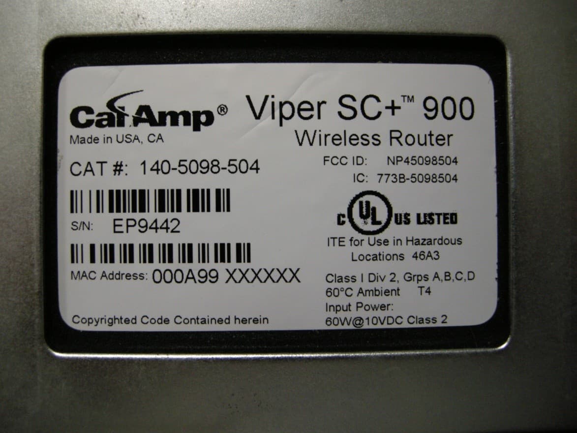
NP45098504
Sep 10, 2013Viper SC+ 928-960 MHz
Equipment Class
PCB - PCS Licensed Transmitter
NP45098304
Aug 29, 2013VIPER SC+ 900 VHF 880-902 MHZ
Equipment Class
PCB - PCS Licensed Transmitter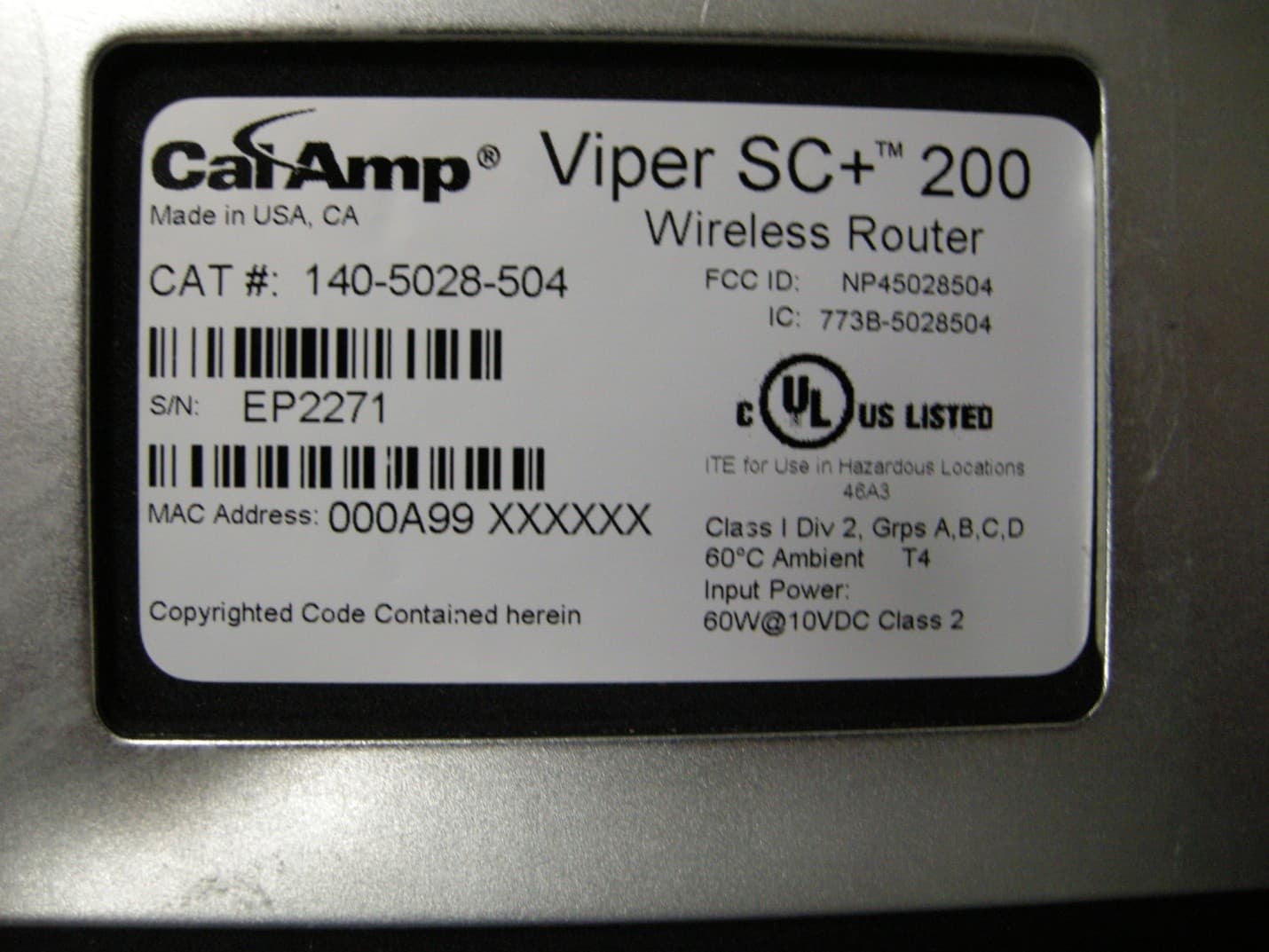
NP45028504
Aug 22, 2013VIPER SC+ 200 VHF 215-240MHZ
Equipment Class
TNB - Licensed Non-Broadcast Station Transmitter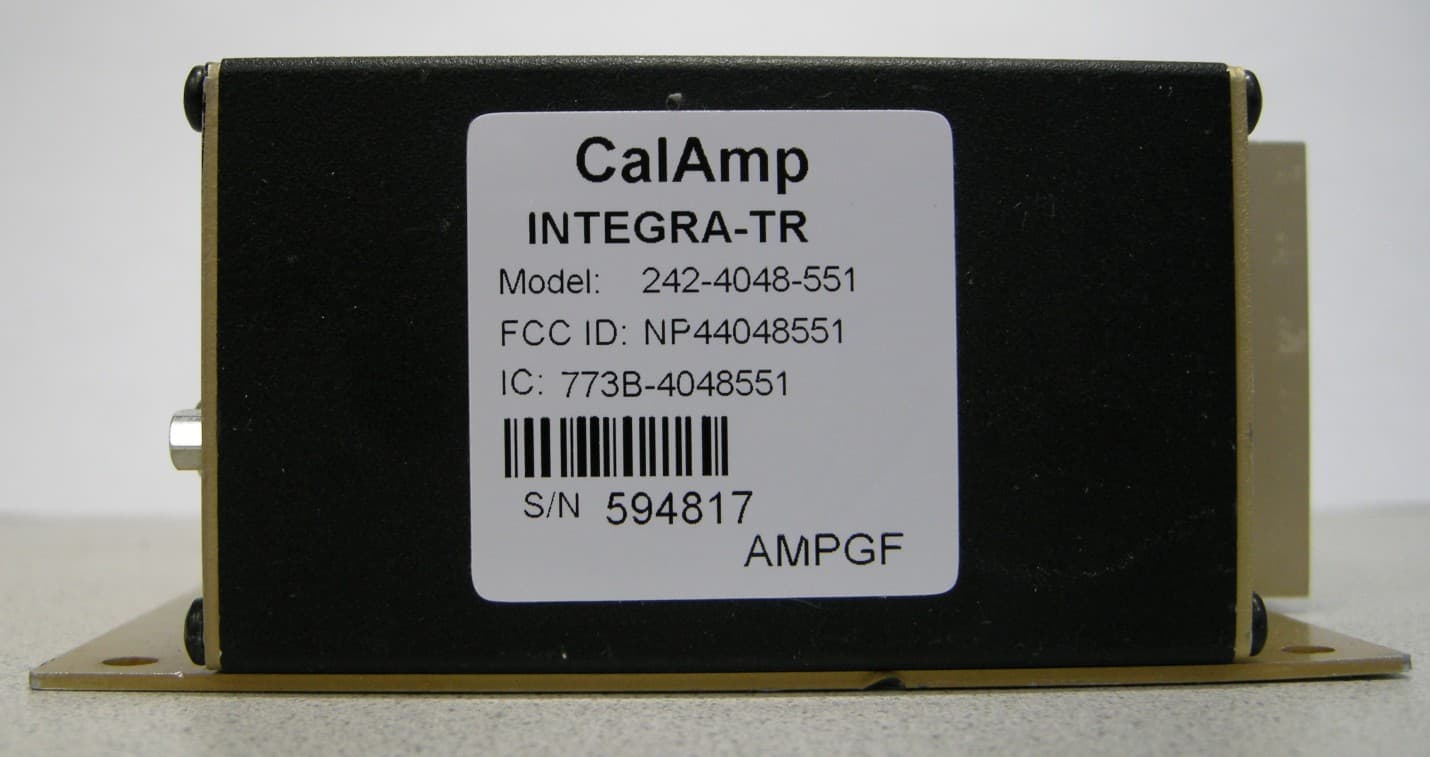
NP44048551
May 09, 2013UHF Wireless Radio Modem
Equipment Class
TNB - Licensed Non-Broadcast Station Transmitter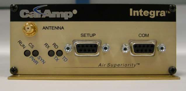
NP44048351
Apr 25, 2013UHF Wireless Radio Modem
Equipment Class
TNB - Licensed Non-Broadcast Station Transmitter