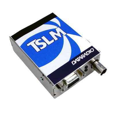
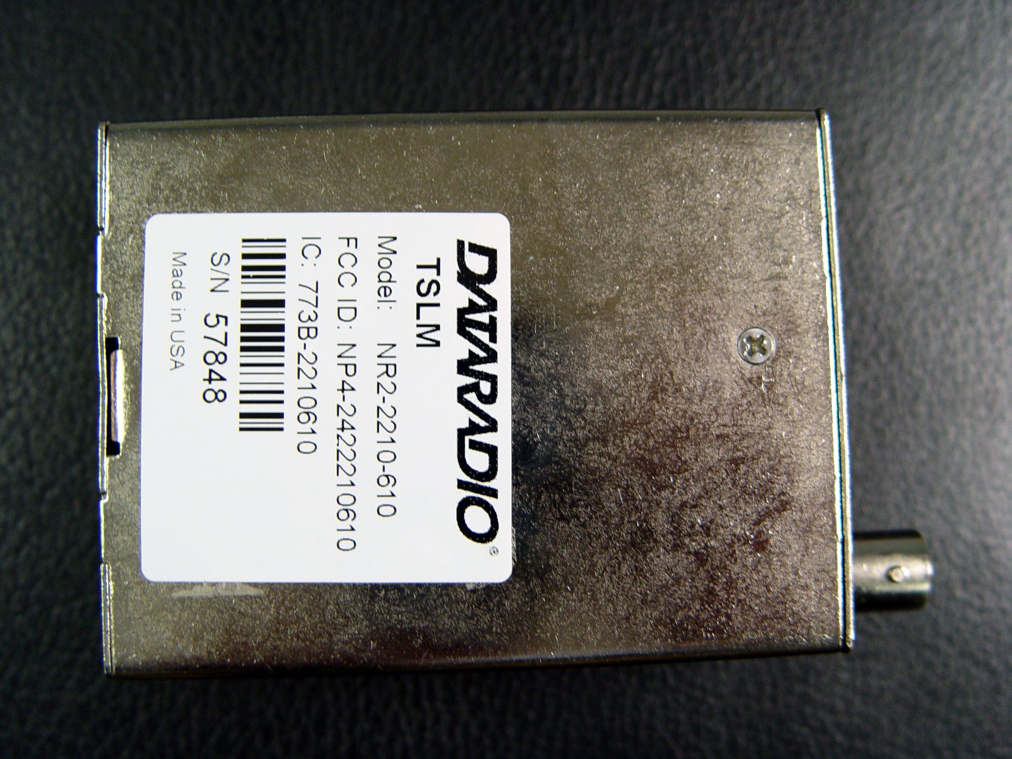
NP4-2422210610TSLM Hi-Spec Integrated Wireless Modem
CalAmp Wireless Networks Corporation
Click to zoom
Application Details
- Equipment Class
- TNB - Licensed Non-Broadcast Station Transmitter
- Date of Grant
- Jan 12, 2006
- Application Purpose
- Original Equipment
- Date of Application
- Jan 11, 2006
- Equipment Note
- TSLM Hi-Spec Integrated Wireless Modem
- Frequency Range
- 150.00000000 - 174.00000000
- Country
- United States
Documents & Files
Document Text
Text extracted from the exhibit documents filed with the FCC. Open a document above to read the original.
Users Manual
Synthesized TSLM Hi-Spec Integrated Wireless Modem Synthesized TSLM Hi Spec Wireless Modem Installation Manual December 2005 001-2200-101 Revision 0 © 2005 by Dataradio COR Ltd. About Dataradio Dataradio is the leading designer and manufacturer of trusted wireless products and systems for critical infrastructure applications. Our products have been found at the heart of mobile and SCADA data networks around the world for over 20 years. Dataradio products include mobile data products and systems, telemetry devices, integrated wireless modems for fixed point-to-point and point to multi-point applications and OEM solutions. Our product line is one of the broadest and most trusted in the industry. Product Warranty The manufacturer's warranty statement for this product is available in our manuals or by contacting COR Ltd. 299 Johnson Avenue, P.O. Box 1733, Waseca, MN 56093-0833. Phone (507) 833-8819. www.dataradio.com Dataradio provides product brochures, case studies software downloads and product information on our website. Every effort is taken to provide accurate, timely product information in this technical manual. Product updates may result in differences between the information provided herein and the product shipped. The information in this document is subject to change without notice. Dataradio is a registered trademark of Dataradio, Inc. SECTION 1 GENERAL INFORMATION 1.1 INTRODUCTION 1.1.1 GENERAL This installation manual provides information for selecting, installing, operating, and maintaining the Dataradio TSLM wireless modem. 1.2 FEATURES The TSLM is a transparent real-time wireless modem designed primarily for SCADA (Supervisory Control and Data Acquisition) and telemetry use. Features of the TSLM include: • Data speeds of 4800 to 9600 b/s maximum in half-channels using a standard RS-232 interface • Built-in 8 channel synthesized radio transceiver for VHF and UHF Power output of 0.10 W to 5 W (software controlled) • Half duplex or simplex operation • Transmit control via RTS • Online diagnostics monitoring • Offline local and remote diagnostics • Compatible with Dataradio T-Base for base station or repeater use • Compatible with any Dataradio Interoperability Standard (DI-OS) equipment including the T-96S for data rates of 4800 and 9600 b/s. 1.3 TSLM PART NUMBER BREAKDOWN The following table shows the breakdown of the TSLM part number. Table 1-1 TSLM Part Number Breakdown 242-22W0-XYZ W X Y Z 1 VHF 6 150-174 MHz 7 137-162 MHz 1 1 12.5 kHz 12.5 kHz 0 0 4 UHF 2 403-422 MHz 2 414-430 MHz 5 450-470 MHz 1 1 1 12.5 kHz 12.5 kHz 12.5 kHz 0 1 0 1.4 ACCESSORIES Table 1-2 TSLM Accessories Accessory DRL Part Number Unterminated Power Cable 023-3276-007 DE-15 to DB-9 Power and Data Cable 697-0000-001 Field Programming Kit 250-2200-001 Factory Mutual NI Kit 023-1000-100 Installation Manual for TSLM 001-2200-102 (CD ROM version) 001-2200-101 (Hard Copy version) DIN Rail Mount 250-4800-406 Switching Power Converter 250-0300-075 (7.5 VDC VOut, 3 Amp) 250-0300-133 (12.5 VDC V Out, 3 Amp) For information about sales and accessories, contact your sales representative. In the U.S. phone 1-800-992-7774 or 1-507-833-8819. 1.5 TRANSCEIVER IDENTIFICATION The transceiver identification number is printed on a label that is affixed to the PC board. The following information is contained in that number: Model Revision Manufacturer Warranty Letter Date Plant Number 22W0 2 A 455 A 12345 Ninth Digit Month Year of PN Figure 1-3 Transceiver Identification Nomenclature 1.6 PRODUCT WARRANTY Dataradio warranties are available in Appendix B and are included in .pdf format on CD versions of Dataradio manuals. 1.7 FACTORY TECHNICAL SERVICE The Technical Service Department of Dataradio COR Ltd. (DRL) provides customer assistance on technical problems and serves as an interface with factory repair facilities. They can be reached by mail, phone, and email at: Dataradio COR Ltd. Technical Service Department 299 Johnson Avenue, P.O. Box 1733 Waseca, MN 56093-0833 1-800-992-7774 or 1-507-833-8819 Fax: 507-833-6748 Email address: [email protected] Technical Service hours: Monday through Friday 7:30 A.M. to 4:30 P.M. Central Time 1.8 REPLACEMENT PARTS This product is not field serviceable, except by the replacement of complete units. Specialized equipment and training is required to repair logic boards and radio modules. 1.9 IF A PROBLEM ARISES... Component level repair is not recommended on the TSLM. DRL’s factory is best equipped to diagnose problems and make component level repairs. Contact Technical Service before returning equipment. A service technician may suggest a solution eliminating the need to return equipment. 1.9.1 FACTORY REPAIR Dataradio products are designed for long life and failure-free operation. If a problem arises, factory service is available. Contact the Technical Service Department before returning equipment. A Return Material Authorization (RMA) is required when returning equipment to Dataradio for repair. Contact the Technical Service Department at 1-800-992-7774 or 1-507-833-8819 (extension 6707) to request an RMA number. RMA’s are available through our website at www.dataradio.com/ products_tech_adv.html. Be prepared to give the equipment model and serial number, your account number (if known), and billing and shipping addresses. Include the RMA number, a complete description of the problem, and the name and phone number of a contact person with the returned units. This information is important. The technician may have questions that need to be answered to identify the problem and repair the equipment. The RMA number helps locate your equipment in the repair lab if there is a need to contact Dataradio concerning the equipment. Units sent in for repair will be returned to the customer re-tuned to the current Dataradio Test and Tune Procedure and will conform to all specifications noted in this section Customers are responsible for shipping charges (to Dataradio) for returned units in warr…
Text truncated - open the document above for the full version.
Cover Letter(s)
Attn: Reviewing Engineer December 15, 2005 Federal Communications Commission 7435 Oakland Mills Road Columbia, MD 21046 RE: CONFIDENTIALITY REQUEST FOR TSLM VHF TELEMETRY TRANSCEIVER FCC ID: NP42422210-610 To Whom It May Concern: This letter serves as an official request for confidentiality under FCC Rule Secton 0.457 and 0.459. We have requested the item listed below as items 1 – 4, required to be submitted with this application be withheld from public review. 1. Circuit Schematics Attachment entitled: TSLM VHF rf schematic diagram.pdf Attachment entitled: TSLM modem schematic diagram.pdf 2. Bills of materials Attachment entitled: TSLM VHF rf bom.pdf Attachment entitled: TSLM modem bom.pdf 3. Block Diagrams Attachment entitled: TSLM VHF rf block diagram.pdf Attachment entitled: TSLM modem block diagram.pdf 4. Circuit Description Attachment entitled: TSLM VHF circuit description.pdf This request is based on the fact that these are proprietary trade secrets of Dataradio. Dataradio does not make this information available to the public. Releasing this information gives competitors an unfair advantage of our proprietary research and development efforts. Sincerely, Mark Christensen Director of Product Development
Cover Letter(s)
American Telecommunications Certification Body Inc. 6731 Whittier Ave, McLean, VA 22101 January 10, 2006 RE: FCC ID: NPR-2422210610_ATCB003082 Attention: Mark A. Christensen I have a few comments on this Application. Please note that further comments may arise in response to answers provided to the questions below. 1. Please note that the installation manual states “The Field Programming Software allows the user to edit and program user programmable settings, interactively tune modem and RF parameters.” Because the statement says the software can tune rf parameters, this indicates that the device may be a software defined radio. Please explain what this statement means and please clearly identify if this is a software defined radio. 2. FYI – as this device also appears to connect to a computer, FCC part 15 issues should be addressed. Dennis Ward mailto:[email protected] The items indicated above must be submitted before processing can continue on the above referenced application. Failure to provide the requested information may result in application termination. Correspondence should be considered part of the permanent submission and may be viewed from the Internet after a Grant of Equipment Authorization is issued. Please do not respond to this correspondence using the email reply button. In order for your response to be processed expeditiously, you must submit your documents through the AmericanTCB.com website. Also, please note that partial responses increase processing time and should not be submitted. Any questions about the content of this correspondence should be directed to the sender.
Cover Letter(s)
299 Johnson Avenue, Suite 110 Waseca, MN 56093-0833 Tel 507-833-8819; Fax 507-833-6748 Wednesday, January 11, 2006 Dennis, 1. The Field Programming Software is used to program limited radio parameters such as power output level, operating frequency, PTT Watchdog Timeout, PTT and Carrier Detect Polarity and etc. The Field Programming Software does not define the construction of the actual modulation waveforms transmitted or the deconstruction of the the modulation waveforms received. The TSLM is not a Software Defined Radio. 2. The device is typically hooked to a computer during factory test and tune operations and is not hooked to a computer in normal operation. We have tested the device to the FCC Part 15.33, 15.109 and 15.111. Regards, Bill Junge Senior Technologist OEM Technical Support Dataradio COR Ltd. 299 Johnson Avenue, Suite 110 Waseca, MN 56093-0833 Phone: 507-833-6733 Fax: 507-833-6748 email: [email protected] Internet: www.dataradio.com Trusted Wireless Data Solutions
Parts List/Tune Up Info
TSLM VHF Transmitter Tuning Procedure The watchdog can be disabled in the Production Test screen but care should be taken to not damage the transmitter if the watchdog is disabled. Arrow to the MID channel. Adjust R560 fully counterclockwise. Verify that the DAC value for TX Power Adj. in the adjustments section of the programmer is 0 (Zero) for MID channel. Key the transmitter F5 and monitor the transmitter current drain. Adjust R560 for 400 ± 50mA greater than the initial current meter reading. Select the TX Power Adj. in the adjustments section of the programmer. Key the transmitter. Using the Page Up/Down (x1) or CTRL Page Up/Down (x10) to adjust the output power for 5.00 Watts ± 1.00 Watt. Key and un-key the transmitter as quickly as possible while setting the power output. Arrow to the Low and High channels and set the output power to 5.00 Watts ± 1.00 Watt in the same manner as described in the previous step. The current should be < 2.0 A across the band. Un-key the transmitter F6. Press F10 to write the values to the EEPROM.
RF Exposure Info
RF Exposure Compliance Requirements TSLM VHF Wireless Modem FCC Rule: 1.1307, 1.1310, 2.1091 (b) (d), 2.1093 Description of Compliance: The TSLM will be professionally installed in the SCADA (Supervisory Control And Data Acquisition) market and will be mounted with a fixed RTU (Remote Terminal Unit). A typical installation would use a maximum gain antenna of 10 dBi mounted on a tower. A minimum separation distance of more than 141 cm must be maintained between the radiating structure and any person to classify as a mobile under FCC MPE regulations. Note: It is the responsibility of the user to guarantee compliance with the FCC MPE regulations when operating this device in a way other than described above. The calculation for the more stringent specification, a General Population/Uncontrolled Mobile device according to section 2.1091(b) and section 1.1310 Note 2 is shown below: Limits for General Population/Uncontrolled Exposure: Frequency Range (MHz) Electric Field Strength (V/m) Magnetic Field Strength (A/m) Power Density (mW/cm 2 ) Averaging Time (mins) 0.3-1.34 614 1.63 *(100) 30 1.34-30 824/f 2.19/f *(180/f2) 30 30-300 27.5 0.073 0.2 30 300-1500 --- --- f (MHz)/1500 (MHz) 30 1500-100000 --- --- 1.0 30 Environmental Specification: 0.2 mW/cm 2 S = (PG)/(4πR 2 ) (OET Bulletin 65) Where: S = Power Density (mW/cm 2 ) P = Power input to the antenna (mW) G = Power Gain of the antenna in the direction of interest relative to an isotropic radiator R = Distance to the center of radiation of the antenna (cm) Distance Calculation: R = √((PG)/(4πS)) Typical Antenna Gain: 10.0 dBi 10 (10.0 dBi/10) = 10.0 Power input to the Antenna: 37dBm = 10 (37dBm/10) = 5000 mW R = √((5000mW*10.0)/(4π*0.2 mW/cm 2 )) = 141 cm (Minimum Distance)
Test Report
Page 1 of 22 DATARADIO COR Ltd. Corporate Headquarters and Manufacturing Operations 299 Johnson Avenue, Suite 110 Waseca, MN 56093-0833 USA Phone: 507-833-8819 Fax: 507-833-6748 FCC Part 90 Certification Application FCC Form 731 For The TSLM VHF Wireless MODEM FCC ID: NP4-2422210610 Page 2 of 22 NAME OF TEST: Transmitter Rated Power Output RULE PART NUMBER: 2.1046 (a) (c) TEST RESULTS: See results below TEST CONDITIONS: Standard Test Conditions TEST EQUIPMENT: 50 Ohm Attenuator, Tenuline Model 8340 / 20 dB / 25 Watt 50 Ohm Attenuator, Tenuline Model 8340 / 10dB / 25 Watt Power Supply, Instek Model GPS-2303 Power Meter, Model HP-436A TEST SET-UP: TEST RESULTS: Frequency DC Voltage atDC Current intoDC Power intoRF Power Output ( MHz ) Final ( Vdc ) Final ( Adc ) Final ( W ) ( W ) 150 12.5 1.24 15.50 5 150 7.2 0.68 4.90 0.1 Page 3 of 22 NAME OF TEST: Transmitter Occupied Bandwidth for Emission Designator RULE PART NUMBER: 2.202, 90.209 (b)(5), 90.210(d), 2.1047 (d), 2.1049 (c) (1) MINIMUM STANDARDS: Mask D Sidebands and Spurious [Rule 90.210 (d), P = 5 Watts and P=0.1 Watt] Authorized Bandwidth = 11.25 kHz [Rule 90.209(b) (5)] From Fo to 5.625 kHz, down 0 dB. Greater than 5.625 kHz to 12.5 kHz, down 7.27(f d -2.88kHz) dB. Greater than 12.5 kHz, at least 50+10log 10 (P) or 70 dB, which ever is the lesser attenuation Attenuation = 0 dB at Fo to 5.625 kHz Attenuation = 20 dB at 5.625 kHz and 70 dB at 12.5 kHz Attenuation = 57 dB at greater than 12.5 kHz @ 5 Watts Attenuation = 40 dB at greater than 12.5 kHz @ 0.1 Watt TEST RESULTS: Meets minimum standards (see data on following page) With 2.5 kHz deviation TEST CONDITIONS: Standard Test Conditions, 25 C TEST PROCEDURE: TIA/EIA – 603-B, 2.2.13, 3.2.11.2 TEST EQUIPMENT: 50 Ohm Attenuators, Pasternack Model PE4131 / 10 dB / 20 Watt 50 Ohm Attenuators, MCL Model 5W-S20 / 20 dB / 5 Watt 50 Ohm Attenuators, Inmet Model 6B-10W / 20 dB / 10 Watt Power Supply, Instek Model GPS-2303 Spectrum Analyzer, Agilent Model E4404B Modulation Analyzer, Model HP8901A TEST SET-UP: Page 4 of 22 Modulation description. This equipment is not provided with hardware audio low-pass filters, the transmit filter is a digital 80 tap FIR filter implemented in the firmware. The digital filter is based on a convolution between two filters, the former built on the raised cosine filter equation and the later built on a brick wall pulse shaping on symbol frequency. The FIR is qualified on the resulting 3dB cut-of frequency. For 9600bps on a half channel, the transmitter filter is a Raised Cosine with Alpha = 1.0, convolved with a rectangular pulse of duration 1/9600 sec. For 4800 bps on a half channel, the transmit filter is a Raised Cosine with Alpha = 1.0. The transmitter deviation level is referenced to a test tone on 1200Hz generated internally. The deviation level and digital filter cutoff frequency are set according to the bit rate selected and channel bandwidth as follows: Bit rate Baud rate FIR filter's 3dB cut-off frequency Deviation 9600 bps 9600 bauds4.4 kHz ± 3.0 kHz 4800 bps 4800 bauds2.4 kHz ± 4.0 kHz The pseudo random test pattern generated by issuing the K command is created by pseudo random bit generator with a repetition period of (2 32 )-1 bits. FIR filter's 3dB cut-off Deviation on Peak deviationOccupied AuthorizedProposed Baud Rate Frequency Bit Rate Reference test toneOn random dataBandwidth BandwidthEmission kHz bps kHz kHz kHz kHz Designator 9600 4.4 9600 2.7 3.0 9.60 11.25 9K6F1D 4800 2.4 4800 3.7 4.0 9.99 11.25 10K0F1D Page 5 of 22 Pwr: 5W, 4800 bps, Peak Dev: 4.0 kHz Pwr: 5W, 9600 bps, Peak Dev: 3.0 kHz Page 6 of 22 Pwr: 0.10W, 4800 bps, Peak Dev: 4.0 kHz Pwr: 0.10W, 9600 bps, Peak Dev: 3.0 kHz Page 7 of 22 NAME OF TEST: Transmitter Spurious and Harmonic Outputs RULE PART NUMBER: 2.1051, 90.210 (d)(3) MINIMUM STANDARDS: For 5 Watts; 50+10Log 10 (5 Watts) = -57 dBc For 0.1 Watts; 50+10Log 10 (0.1 Watts) = -40 dBc or –70 dBc whichever is the lesser attenuation. TEST RESULTS: Meets minimum standards ( see data on following page ) TEST CONDITIONS: Standard Test Conditions, 25 C RF Voltage measured at antenna terminals TEST PROCEDURE: TIA/EIA – 603-B, 2.2.13 TEST EQUIPMENT: 50 Ohm Attenuators, Pasternack Model PE4131 / 10 dB / 20 Watt 50 Ohm Attenuators, MCL Model 5W-S20 / 20 dB / 5 Watt 50 Ohm Attenuators, Inmet Model 6B-10W / 20 dB / 10 Watt Power Supply, Instek Model GPS-2303 Spectrum Analyzer, Advantest Model R3265A Reference Generator, Agilent Model E82570 Notch Filter TEST SET-UP: MEASUREMENT PROCEDURE: 1. The transmitter carrier output frequency is 137.000, 162.000, 150.000, and 174.000. The reference oscillator frequency is 16.000 MHz. The transmitter has voltage levels at 12.5 Volts and 7.2 Volts. 2. After the carrier reference was established on the spectrum analyzer, the notch filter was adjusted to null the carrier fundamental to extend the range of the spectrum analyzer for harmonic measurements. 3. At each spurious frequency, generation substitution was used to establish the true spurious level. 4. The spectrum was scanned to the 10 th harmonic Page 8 of 22 TEST DATA: Fo 137.000MHz Pwr (@ 12.5 V) 37.00dBm Spec -57dBc Harmonic Freq. (MHz)Level Relative to Carrier (dBc)Passed by (dB) 2 nd 274 -62.14 5.137 3 rd 411 -76.03 19.03 4 th 548 -83.74 26.74 5 th 685 -94.38 37.38 6 th 822 -98.99 41.99 7 th 959 -99.01 42.01 8 th 1096 -96.34 39.34 9 th 1233 -97.37 40.37 10 th 1370 -103.13 46.13 Fo 162.000MHz Pwr (@ 12.5 V) 37.00dBm Spec -57dBc Harmonic Freq. (MHz)Level Relative to Carrier (dBc)Passed by (dB) 2 nd 324 -59.50 2.50 3 rd 486 -74.35 17.35 4 th 648 -83.35 26.35 5 th 810 -92.08 35.08 6 th 972 -97.38 40.38 7 th 1134 -95.81 38.81 8 th 1296 -96.70 39.70 9 th 1458 -97.41 40.41 10 th 1620 -99.39 42.39 Fo 150.000MHz Pwr (@ 12.5 V) 37.00dBm Spec -57dBc Harmonic Freq. (MHz)Level Relative to Carrier (dBc)Passed by (dB) 2 nd 300 -60.40 3.40 3 rd 450 -74.54 17.54 4 th 600 -84.59 27.59 5 th 750 -94.29 37.29 6 th 900 -99.44 42.44 7 th 1050 -98.70 41.70 8 th 120…
Text truncated - open the document above for the full version.
Contact Information
Applicant
Russell Cook(Director of Engineering)
Technical Contact
Dataradio COR Ltd.Mark A Christensen
299 Johnson Avenue � Suite 110 · Waseca, Minnesota · United States
Technical Specifications
| # | Rule Parts | Frequency Range | Power Output | Emission | Tolerance |
|---|---|---|---|---|---|
| 4 | 90.21 | 150 MHz - 174 MHz | 5 W | 10K0F1D | 1 ppm |
Other Applications from CalAmp Wireless Networks Corporation
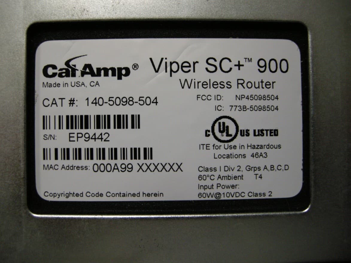
NP45098504
Sep 10, 2013Viper SC+ 928-960 MHz
Equipment Class
PCB - PCS Licensed Transmitter
NP45098304
Aug 29, 2013VIPER SC+ 900 VHF 880-902 MHZ
Equipment Class
PCB - PCS Licensed Transmitter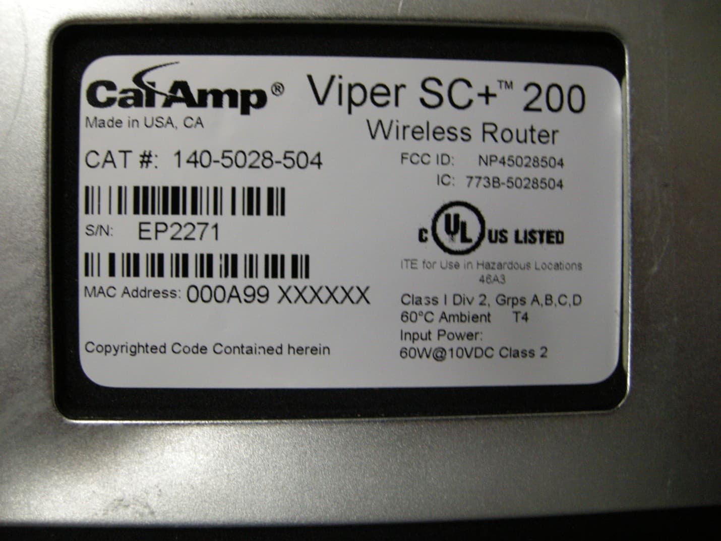
NP45028504
Aug 22, 2013VIPER SC+ 200 VHF 215-240MHZ
Equipment Class
TNB - Licensed Non-Broadcast Station Transmitter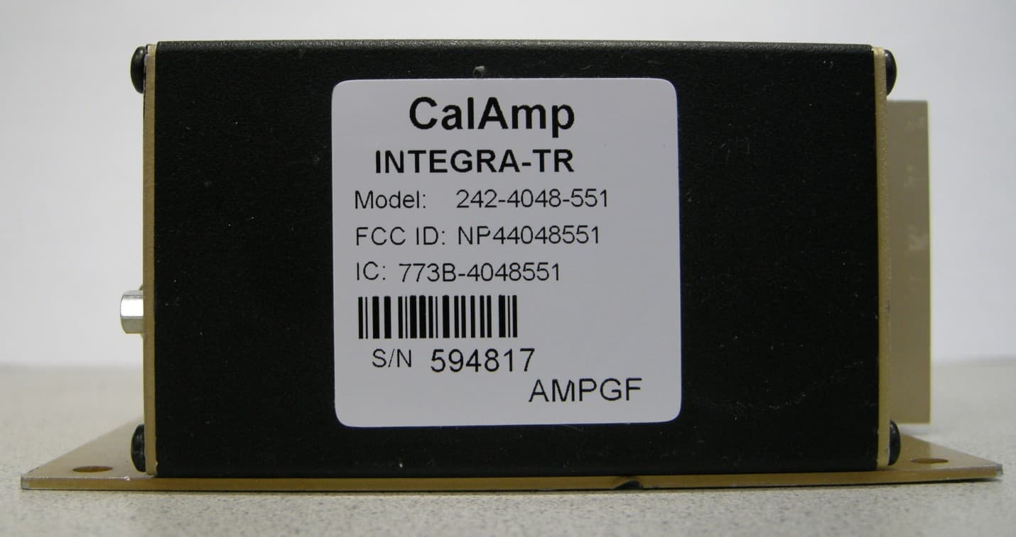
NP44048551
May 09, 2013UHF Wireless Radio Modem
Equipment Class
TNB - Licensed Non-Broadcast Station Transmitter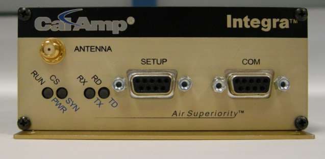
NP44048351
Apr 25, 2013UHF Wireless Radio Modem
Equipment Class
TNB - Licensed Non-Broadcast Station Transmitter