NP4-5026-500Guardian 200 Wireless Radio Modem
CalAmp Wireless Networks Corporation
Click to zoom
Application Details
- Equipment Class
- TNB - Licensed Non-Broadcast Station Transmitter
- Date of Grant
- Apr 11, 2011
- Application Purpose
- Original Equipment
- Date of Application
- Apr 11, 2011
- Equipment Note
- Guardian 200 Wireless Radio Modem
- Frequency Range
- 216.00000000 - 220.00000000
- Country
- United States
Documents & Files
Document Text
Text extracted from the exhibit documents filed with the FCC. Open a document above to read the original.
Users Manual
GUARDIAN™ HIGH SPEC RADIO MODEM User Manual PN 001‐5006‐000 Rev 0 Revised February 2010 REVISION HISTORY REV DATE REVISION DETAILS 0 February 25, 2010 Initial Release as 001‐5006‐000. IMPORTANT NOTICE Because of the nature of wireless communication, transmission and reception of data can never be guaranteed. Data may be delayed, corrupted (i.e., have errors), or be totally lost. Significant delays or losses of data are rare when wireless devices such as the Guardian are used in a normal manner with a well‐constructed network. Guardian should not be used in situations where failure to transmit or receive data could result in damage of any kind to the user or any other party, including but not limited to personal injury, death, or loss of property. CalAmp accepts no responsibility for damages of any kind resulting from delays or errors in data transmitted or received using Guardian, or for the failure of Guardian to transmit or receive such data. COPYRIGHT NOTICE © Copyright 2007 CalAmp. Products offered may contain software proprietary to CalAmp. The offer of supply of these products and services does not include or infer any transfer of ownership. No part of the documentation or information supplied may be divulged to any third party without the express written consent of CalAmp. RF EXPOSURE COMPLIANCE REQUIREMENTS The Guardian radio is intended for use in the Industrial Monitoring and Control and SCADA markets. The Guardian unit must be professionally installed and must ensure a minimum separation distance listed in the table below between the radiating structure and any person. An antenna mounted on a pole or tower is the typical installation and in rare instances, a 1/2‐wave whip antenna is used. Antenna Gain 5 dBi 10 dBi 15 dBi Min Safety Distance (VHF @ max Power) 123cm 218.8cm 389cm Min Safety Distance (UHF @ max Power) 105.7cm 188cm 334.4cm Min Safety Distance (900 MHz @ max power) 63.8cm 115 cm 201.7 cm Note: It is the responsibility of the user to guarantee compliance with the FCC MPE regulations when operating this device in a way other than described above. The Guardian radio uses a low power radio frequency transmitter. The concentrated energy from an antenna may pose a health hazard. People should not be in front of the antenna when the transmitter is operating. The installer of this equipment must ensure the antenna is located or pointed such that it does not emit an RF field in excess of Health Canada limits for the general population. Recommended safety guidelines for the human exposure to radio frequency electromagnetic energy are contained in the Canadian Safety Code 6 (available from Health Canada) and the Federal Communications Commission (FCC) Bulletin 65. Any changes or modifications not expressly approved by the party responsible for compliance (in the country where used) could void the user's authority to operate the equipment. RF E REGULATORY CERTIFICATIONS The Guardian radio is available in several different models each with unique frequency bands. Each model of Guardian may have different regulatory approval as shown in the table below. UL Certification All models UL approved when powered with a listed Class 2 source. DECLARATION OF CONFORMITY FOR MODEL # 140-5046-400 This device (Guardian model #140‐5046‐400) is a data transceiver intended for commercial and industrial use in all EU and EFTA member states. Česky [Czech] CalAmp tímto prohlašuje, že tento rádio je ve shodě se základními požadavky a dalšími příslušnými ustanoveními směrnice 1999/5/ES. Dansk [Danish] Undertegnede CalAmperklærer herved, at følgende udstyr radio overholder de væsentlige krav og øvrige relevante krav i direktiv 1999/5/EF. Deutsch [German] Hiermit erklärt CalAmp, dass sich das Gerät radio in Übereinstimmung mit den grundlegenden Anforderungen und den übrigen einschlägigen Bestimmungen der Richtlinie 1999/5/EG befindet. Eesti [Estonian] Käesolevaga kinnitab CalAmpseadmeraadiovastavust direktiivi 1999/5/EÜ põhinõuetele ja nimetatud direktiivist tulenevatele teistele asjakohastele sätetele. English Hereby, CalAmp,declares that this radiois in compliance with the essential requirements and other relevant provisions of Directive 1999/5/EC. Español [Spanish] Por medio de la presente CalAmpdeclara que el radiocumple con los requisitos esenciales y cualesquiera otras disposiciones aplicables o exigibles de la Directiva 1999/5/CE. Ελληνική [Greek] ΜΕ ΤΗΝ ΠΑΡΟΥΣΑCalAmpΔΗΛΩΝΕΙ ΟΤΙ ΡΑΔΙΌΦΩΝΟΣΥΜΜΟΡΦΩΝΕΤΑΙ ΠΡΟΣ ΤΙΣ ΟΥΣΙΩΔΕΙΣ ΑΠΑΙΤΗΣΕΙΣ ΚΑΙ ΤΙΣ ΛΟΙΠΕΣ ΣΧΕΤΙΚΕΣ ΔΙΑΤΑΞΕΙΣ ΤΗΣ ΟΔΗΓΙΑΣ 1999/5/ΕΚ. Français [French] Par la présente CalAmpdéclare que l'appareil radioest conforme aux exigences essentielles et aux autres dispositions pertinentes de la directive 1999/5/CE. Italiano [Italian] Con la presente CalAmpdichiara che questo radioèconforme ai requisiti essenziali ed alle altre disposizioni pertinenti stabilite dalla direttiva 1999/5/CE. Latviski [Latvian] Ar šo CalAmpdeklarē, ka radioatbilst Direktīvas 1999/5/EK būtiskajām prasībām un citiem ar to saistītajiem noteikumiem. Lietuvių Šiuo CalAmpdeklaruoja, kad šisradijoatitinka esminius reikalavimus ir kitas 1999/5/EB Certifications Model Number Frequency Range FCC IC (DOC) European Union EN 300 113 Australia/New Zealand 140-5016-500 136 – 174 MHz NP4-5016-500 773B-5016500 140-5016-501 136 – 174 MHz NP4-5016-500 773B-5016500 140-5026-500 216 – 222 MHz NP4-5026-500 773B-5026500 140-5026-501 216 – 222 MHz NP4-5026-500 773B-5026500 140-5046-300 406 - 470 MHz NP4-5046-500 773B-5046500 140-5046-301 406 - 470 MHz NP4-5046-500 773B-5046500 140-5046-500 450 - 512 MHz NP4-5046-500 773B-5046500 140-5046-501 450 - 512 MHz NP4-5046-500 773B-5046500 140-5096-500 928 - 960 MHz NP4-5096-500 773B-5096500 140-5096-501 928 - 960 MHz NP4-5096-500 773B-5096500 [Lithuanian] Direktyvos nuostatas. Nederlands [Dutch] Hierbij verklaart CalAmpdat het toestelradioin overeenstemming is met de essentiële eisen en de andere relevante bepalingen van richtlijn 1999/5/EG. Malti [Maltes…
Text truncated - open the document above for the full version.
Attestation Statements
Calamp Wireless Networks Corporation Waseca, Minnesota Calamp Wireless Networks Corporation hereby requests that our grant for NP4-5026-500 list frequencies outside of the FCC allocated Part 80 and Part 90 frequencies. Calamp Wireless Networks Corporation acknowledges that it is a violation of FCC rules if the device operates on unauthorized frequencies. The device is professionally installed and it is up to the installer to determine if the device operates on authorized frequencies. The device was tested and complies with the associated standards between Part 80 and Part 90 across the frequency range 216-222MHz. Chris Ludewig Director of Engineering
Cover Letter(s)
101210-19 THIS MUST BE SIGNED BY THE APPLICANT AND SHOULD BE PLACED ON APPLICANTS LETTERHEAD ONLY IF AGENT IS SUBMITTING APPLICATION Attn: Director of Certification Authority to Act as Agent I appoint American Certification Body Inc.__ to act as our agent in the preparation of this application for equipment certification. I certify that submitted documents properly describe the device or system for which equipment certification is sought. I also certify that each unit manufactured, imported or marketed, as defined in Industry Canada’s regulations will have affixed to it a label identical to that submitted for approval with this application. For instances where our authorized agent signs the application for certification on our behalf, I acknowledge that all responsibility for complying with the terms and conditions for Certification, as specified by American Certification Body, Inc. (ACB), still resides with ___(applicant name and address)___. Dated this 17 th day of December, 2010. Agency Agreement Expiration Date: (Typically 8-12 months) By: __________________ _Chris Ludewig____________ (Signature) (Print name) Title: _Director of Engineering___________ On behalf of: Calamp Wireless Networks Corpoeration_______________ (Company Name) Telephone: ____________507-833-6717______________
Cover Letter(s)
Attn: Reviewing Engineer December 27, 2010 Federal Communications Commission 7435 Oakland Mills Road Columbia, MD 21046 RE: CONFIDENTIALITY REQUEST FOR Guardian RADIO TRANSCEIVER FCC ID: NP4-5026-500 To Whom It May Concern: This letter serves as an official request for confidentiality under FCC Rule Secton 0.457 and 0.459. We have requested the item listed below as items 1 – 4, required to be submitted with this application be withheld from public review. 1. Circuit Schematics Attachment entitled: #11 Guardian LED Display Board Schematic.pdf Attachment entitled: #11 Guardian Modem Schematic.pdf Attachment entitled: #11 Guardian RF Board Schematic.pdf 2. Bills of materials Attachment entitled: #12 Guardian LED Display Board BOM.pdf Attachment entitled: #12 Guardian Modem BOM.pdf Attachment entitled: #12 Guardian RF BOM.pdf 3. Block Diagrams Attachment entitled: #10 Guardian LED Display Board Block Diagram.pdf Attachment entitled: #10 Guardian Modem Block Diagram.pdf Attachment entitled: #10 Guardian RF Block Diagram.pdf 4. Circuit Description Attachment entitled: #5 Guardian Circuit Description.pdf This request is based on the fact that these are proprietary trade secrets of CalAmp. CalAmp does not make this information available to the public. Releasing this information gives competitors an unfair advantage of our proprietary research and development efforts. Sincerely, Chris Ludewig Director of Engineering
Cover Letter(s)
General Information The following report has been generated for FCC Certification of Calamp Wireless Networks Corporation Model 140-5026-500, VHF Transceiver. Unless otherwise noted, all of the measurements were conducted following the procedures set forth in the TIA/EIA-603-C standards. Trade Name: Guardian Model Number: 140-5026-500 Manufacturer: Calamp Wireless Networks Corporation Waseca, MN 56093 FCC ID Number: FCC ID: NP4-5026-500 FCC Rules and Regulations: FCC Part 80, 90 Frequency Range: 216-222 MHz Serial Number (s): Pilot #1 Transmitter: Type of Emissions: 9K55F1D 9K35F1D 11K6F1D 14K6F1D 16K4F1D Maximum Power Ratings: 12 Watts Number of Channels: 8 Input Impedance: 50 Ohms, Nominal Voltage Requirement: 10-30 Vdc
External Photos
External Photos for the Guardian 200 Top, Front, Left Side Bottom, Back, Right Side Duplex Radio Radio with Fan Option
Internal Photos
Internal Photos for the Guardian 200 LED Display Board Bottom Top In Chassis Bottom In Chassis Top RF Board Simplex Top Bottom Top with Shields In Chassis With Mid-Plate RF Board Duplex Top Bottom With Shields In Chassis With Mid-Plate Guardian Modem Board Top Bottom In Chassis
Parts List/Tune Up Info
Guardian Tune Up Procedure The radio will be connected to an automatic testing station where a software program will tune all the radio parameters. The following instructions summarize the procedure for tuning the output power. The tuning program will key up the radio at four points across the band and sets the power to 10W. Power control is achieved by controlling the voltage on the first stage of the transmitter, which controls the RF drive to the following stages. The power output is programmable by using a digital to analog converter (DAC) on the RF board. This DAC is controlled by the on-board microprocessor. Once the DAC value is determined for these four frequencies the processor interpolates the DAC value for frequencies in between the calibrated frequencies. This ensures equal power output across the entire RF band. The tuning program then will tune the radio at four points across the band at 1W by following the same procedure. The processor interpolates the DAC value for power values between the calibrated powers. Note: Deviation is a preprogrammed set value for all radios.
RF Exposure Info
RF Exposure Compliance Requirements Guardian Analog Telemetry Radio Modem FCC Rule: 1.1307, 1.1310, 2.1091 (b) (d), 2.1093 Description of Compliance: The Guardian will be professionally installed in the SCADA (Supervisory Control And Data Acquisition) market and will be mounted with a fixed RTU (Remote Terminal Unit). A minimum separation distance listed in the table below must be maintained between the radiating structure and any person to classify as a mobile under FCC MPE regulations. Antenna Gain vs. Recommended Safety Distance Antenna Gain 5 dBi 10 dBi 15 dBi Min Safety Distance (max power) 122.8cm 218.4 cm 388.4 cm Note: It is the responsibility of the user to guarantee compliance with the FCC MPE regulations when operating this device in a way other than described above. The calculation for the more stringent specification, a General Population/Uncontrolled Mobile device according to section 2.1091(b) and section 1.1310 Note 2 is shown below: Limits for General Population/Uncontrolled Exposure: Frequency Range (MHz) Electric Field Strength (V/m) Magnetic Field Strength (A/m) Power Density (mW/cm 2 ) Averaging Time (mins) 0.3-1.34 614 1.63 *(100) 30 1.34-30 824/f 2.19/f *(180/f2) 30 30-300 27.5 0.073 0.2 30 300-1500 --- --- f (MHz)/1500 (MHz) 30 1500-100000 --- --- 1.0 30 Environmental Specification: 0.2 mW/cm 2 S = (PG)/(4R 2 ) (OET Bulletin 65) Where: S = Power Density (mW/cm 2 ) P = Power input to the antenna (mW) G = Power Gain of the antenna in the direction of interest relative to an isotropic radiator R = Distance to the center of radiation of the antenna (cm) Distance Calculation for 5dBi antenna: R = ((PG)/(4S)) Antenna Gain: 5.0 dBi 10 (5 dBi/10) = 3.16 Power input to the Antenna: 40.8dBm = 10 (40.8dBm/10) = 12000 mW R = ((12000mW*3.16)/(4*0.2 mW/cm 2 )) = 122.8 cm (Minimum Distance) Distance Calculation for 10dBi antenna: R = ((PG)/(4S)) Antenna Gain: 10.0 dBi 10 (10 dBi/10) = 10 Power input to the Antenna: 40.0dBm = 10 (40.8dBm/10) = 12000 mW R = ((12000mW*10)/(4*0.2 mW/cm 2 )) = 218.5 cm (Minimum Distance) Distance Calculation for 15dBi antenna: R = ((PG)/(4S)) Antenna Gain: 15.0 dBi 10 (15dBi/10) = 31.6 Power input to the Antenna: 40.0dBm = 10 (40.8dBm/10) = 12000 mW R = ((12000mW*31.6)/(4*0.2 mW/cm 2 )) = 388.4 cm (Minimum Distance)
Test Report
Page 1 of 54 CAlamp Wireless Networks Corp. 299 Johnson Avenue, Suite 110 Waseca, MN 56093-0833 USA Phone: 507-833-8819 Fax: 507-833-6748 FCC Part 80/90 Certification Application FCC Form 731 For The Guardian 200 VHF RADIO MODEM FCC ID: NP4-5026-500 Page 2 of 54 TABLE OF CONTENTS Page # Test 1: Transmitter Rated Output Power 3 Test 2: Transmitter Spurious and Harmonic Output 4 Test 3: Frequency Stability with Variation in Supply Voltage 9 Test 4: Frequency Stability with Variation in Ambient Temperature 11 Test 6: Transmitter Occupied Bandwidth - Mask D 14 12.5 kHz Channel Mask D 16 25 kHz Channel Mask C 23 12.5 / 25 kHz Channel Mask F 33 Test 7: Field Strength of Spurious Radiation 45 Calibration Information 54 Page 3 of 54 NAME OF TEST: Transmitter Rated Power Output RULE PART NUMBER: FCC: 2.1046 (a) (c), 80.215 Note: All data taken at 12 watts is to be applied to Part 80 and Part 90 (220-222 MHz) only. Data taken at 2 watts is to be applied to Part 90 (217-220 MHz). TEST RESULTS: See results below TEST CONDITIONS: Standard Test Conditions TEST EQUIPMENT: 50-Ohm Attenuator, Bird 50-A-FFN-20 / 20 dB / 50 Watt Power Supply, Instek Model GPS-3303 Digital Multimeter, Fluke 87 Power Meter, Model HP-8901B TEST SET-UP: TEST RESULTS: Frequency ( MHz ) DC Voltage at Final ( Vdc ) DC Current into Final ( Adc ) DC Power into Final ( W ) RF Power Output ( W ) 217.50625 11.9 2.246 26.7 12.0 217.50625 8.4 .972 8.1 2.0 217.50625 8.0 .724 5.8 1.0 219.50625 11.9 2.148 25.5 12.0 219.50625 8.4 .945 7.9 2.0 219.50625 8.0 .697 5.6 1.0 TEST UNIT ATTENUATOR POWER METER POWER SUPPLY DIGITAL MULTIMETER Page 4 of 54 NAME OF TEST: Transmitter Spurious and Harmonic Outputs RULE PART NUMBER: 2.1051, 90.210 (c,3)(d,3), 80.211 (f) Note: All data taken at 12 watts is to be applied to Part 80 and Part 90 (220-222 MHz) only. Data taken at 2 watts is to be applied to Part 90 (217-220 MHz). MINIMUM STANDARDS: For 12 Watts: 55+10Log 10 (12 Watts) = -65.8 dBc or -70 dBc, whichever is the lesser attenuation. For 2 Watts: 50+10Log 10 (2 Watts) = -50.3 dBc or -65dBc, whichever is the lesser attenuation. For 1 Watt: 55+10Log 10 (1 Watt) = -55 dBc or –70 dBc, whichever is the lesser attenuation. TEST RESULTS: Meets minimum standards ( see data on following pages ) TEST CONDITIONS: Standard Test Conditions, 25 C RF Voltage measured at antenna terminals TEST PROCEDURE: TIA/EIA – 603-C TEST EQUIPMENT: 50-Ohm Attenuator, Narda 765-10 / 10 dB / 50 Watts 50-Ohm Attenuator, Bird 10-A-MFN-10 / 10 dB / 10 Watts Power Supply, Instek Model GPS-3303 Spectrum Analyzer, HP-8563E Reference Generator, Agilent E8257D High Pass Filter, Mini Circuits VHF-740, Fc = 740 MHz TEST SET-UP: MEASUREMENT PROCEDURE: 1. The transmitter carrier output frequency is 217.50625 and 219.50625 MHz. The reference oscillator frequency is 23.040 MHz. The power amplifier has voltage levels at 11.9 Volts and 8.0 Volts for 12 watts and 1 watt, respectively. 2. The carrier reference was established on the spectrum analyzer with the filter by-pass in place. Then the spectrum was scanned from DC to 2 Fc. Finally, the high pass filter was inserted to null Filter By-Pass TEST UNIT ATTENUATORS HIGH PASS FILTER POWER SUPPLY SPECTRUM ANALYZER REFERENCE GENERATOR POWER METER Page 5 of 54 the carrier fundamental and extend the range of the spectrum analyzer for harmonic measurements above 2 Fc. 3. At each spurious frequency, generation substitution was used to establish the true spurious level. 4. The spectrum was scanned to the 10 th harmonic of the highest internally generated frequency. Page 6 of 54 Tuned Frequency 1 217.025 MHz Tuned Frequency 217.025 MHz Power 12.0 Watts Power 1.0 Watts 40.8 dBm 30.0 dBm Min Specification -65.0 dBc Min Specification -55.0 dBc Worse Case -68 dBc Worse Case -87 dBc Spurious Relative to Spurious Relative to Frequency (MHz) Harmonic Carrier (dBc) Frequency (MHz) Harmonic Carrier (dBc) 436.050 2 -86 436.050 2 -87 654.075 3 -68 654.075 3 -91 872.100 4 -106 872.100 4 -112 1090.125 5 -113 1090.125 5 -112 1308.150 6 -117 1308.150 6 -112 .1526.175 7 -122 .1526.175 7 -112 1744.200 8 -122 1744.200 8 -112 1962.225 9 -122 1962.225 9 -112 4360.500 10 -122 4360.500 10 -112 Tuned Frequency 218.025 MHz Power 2.0 Watts 33 dBm Min Specification -65.0 dBc Worse Case -92.44 dBc Spurious Relative to Frequency (MHz) Harmonic Carrier (dBc) 436.050 2 -92.44 654.075 3 -99.94 872.100 4 -117.17 1090.125 5 -121.42 1308.150 6 -125.45 .1526.175 7 -126.8 1744.200 8 -126.8 1962.225 9 -126.8 2180.250 10 -126.8 Page 7 of 54 Tuned Frequency 1 219.925 MHz Tuned Frequency 219.925 MHz Power 12.0 Watts Power 1.0 Watts 40.8 dBm 30.0 dBm Min Specification -65.0 dBc Min Specification -55.0 dBc Worse Case -66 dBc Worse Case -87 dBc Spurious Relative to Spurious Relative to Frequency (MHz) Harmonic Carrier (dBc) Frequency (MHz) Harmonic Carrier (dBc) 436.050 2 -80 436.050 2 -87 654.075 3 -66 654.075 3 -88 872.100 4 -105 872.100 4 -112 1090.125 5 -114 1090.125 5 -112 1308.150 6 -116 1308.150 6 -112 .1526.175 7 -122 .1526.175 7 -112 1744.200 8 -122 1744.200 8 -112 1962.225 9 -122 1962.225 9 -112 4360.500 10 -122 4360.500 10 -112 Page 8 of 54 Tuned Frequency 220.1 MHz Tuned Frequency 220.1 MHz Power 12.0 Watts Power 1.0 Watts 40.8 dBm 30.0 dBm Min Specification -65.0 dBc Min Specification -55.0 dBc Worse Case -66 dBc Worse Case -87 dBc Spurious Relative to Spurious Relative to Frequency (MHz) Harmonic Carrier (dBc) Frequency (MHz) Harmonic Carrier (dBc) 442.050 2 -79 442.050 2 -87 663.075 3 -66 663.075 3 -88 884.100 4 -105 884.100 4 -112 1105.125 5 -113 1105.125 5 -112 1326.150 6 -117 1326.150 6 -112 1547.175 7 -122 1547.175 7 -112 1768.200 8 -122 1768.200 8 -112 1989.225 9 -122 1989.225 9 -112 4420.500 10 -122 4420.500 10 -112 Tuned Frequency 221.025 MHz Tuned Frequency 221.025 MHz Power 12.0 Watts Power 1.0 Watts 40.8 dBm 30.0 dBm Min Specification -65.0 dBc Min Specification -55.0 dBc Worse Case -65 dBc Worse Case -86 dBc Spurious Relative to Spurious Relative to Frequency (MHz) Harmon…
Text truncated - open the document above for the full version.
Test Setup Photos
Photos of OATS 773B-1
Contact Information
Applicant
Russell Cook(Director of Engineering)
Technical Contact
CalAmp Wireless Networks Corp.Dale Jordan
[email protected]507-833-6750
299 Johnson Ave. · Waseca, Minnesota · United States
Test Firm
CalAmp Wireless Networks CorpChris Ludewig
Technical Specifications
| # | Rule Parts | Frequency Range | Power Output | Emission | Tolerance |
|---|---|---|---|---|---|
| 1 | 80,9 | 216 MHz - 220 MHz | 1 W | 16K4F1D | 1 ppm |
Other Applications from CalAmp Wireless Networks Corporation
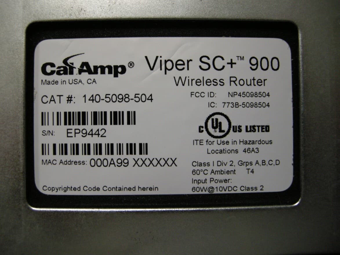
NP45098504
Sep 10, 2013Viper SC+ 928-960 MHz
Equipment Class
PCB - PCS Licensed Transmitter
NP45098304
Aug 29, 2013VIPER SC+ 900 VHF 880-902 MHZ
Equipment Class
PCB - PCS Licensed Transmitter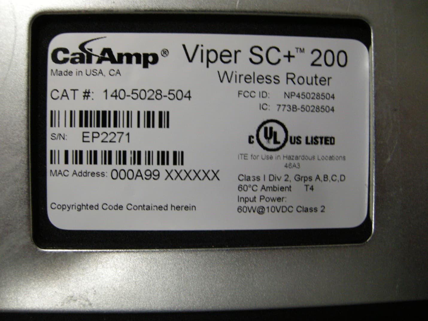
NP45028504
Aug 22, 2013VIPER SC+ 200 VHF 215-240MHZ
Equipment Class
TNB - Licensed Non-Broadcast Station Transmitter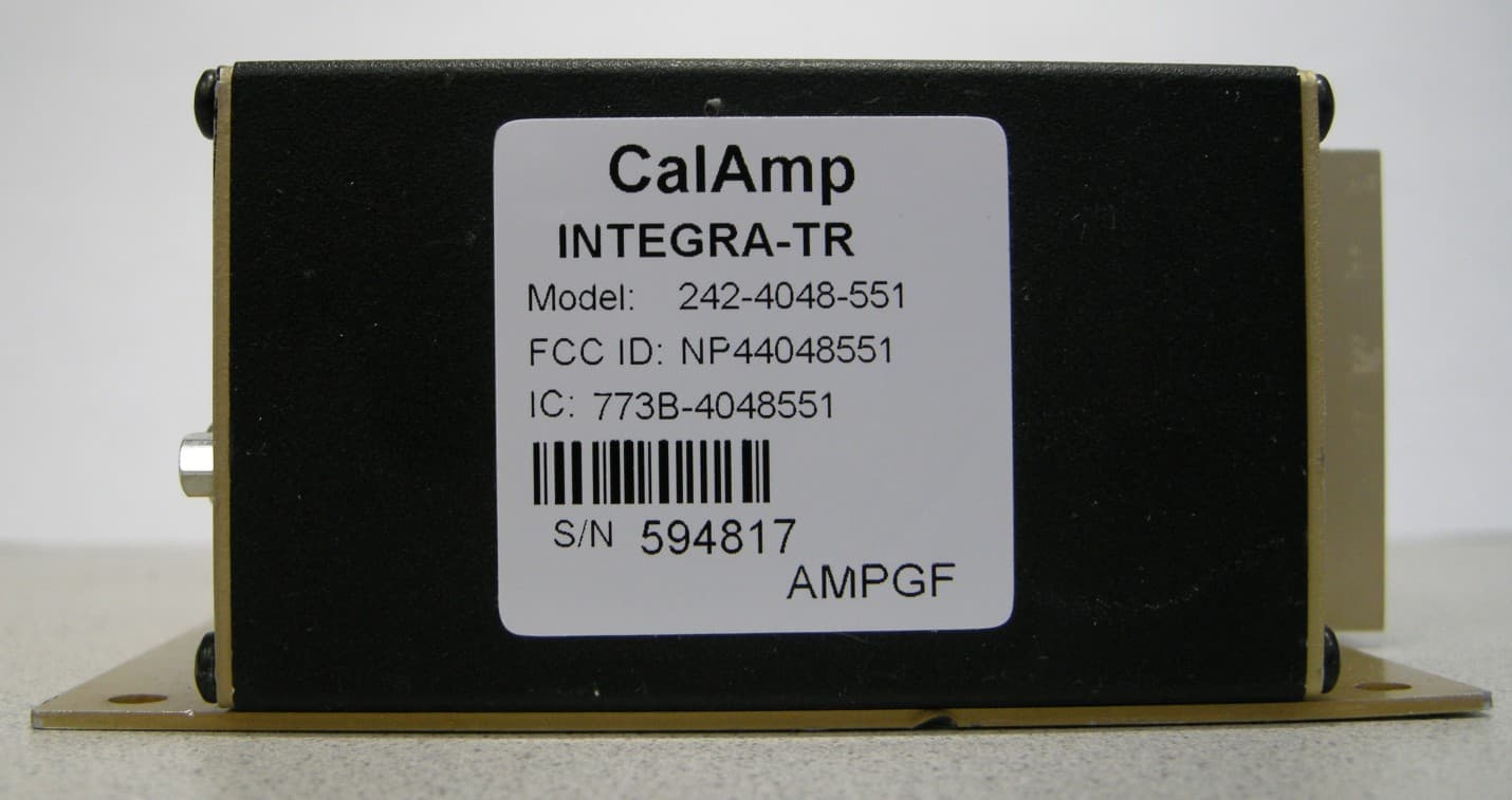
NP44048551
May 09, 2013UHF Wireless Radio Modem
Equipment Class
TNB - Licensed Non-Broadcast Station Transmitter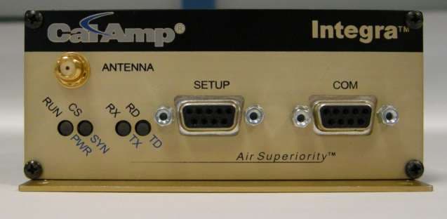
NP44048351
Apr 25, 2013UHF Wireless Radio Modem
Equipment Class
TNB - Licensed Non-Broadcast Station Transmitter