NP4-5048-300Wireless Modem
CalAmp Wireless Networks Corporation
Click to zoom
Application Details
- Equipment Class
- TNB - Licensed Non-Broadcast Station Transmitter
- Date of Grant
- Jun 12, 2007
- Application Purpose
- Original Equipment
- Date of Application
- Jun 12, 2007
- Equipment Note
- Wireless Modem
- Frequency Range
- 406.10000000 - 512.00000000
- Country
- United States
Documents & Files
Document Text
Text extracted from the exhibit documents filed with the FCC. Open a document above to read the original.
Users Manual
ViPR Wireless Radio Modem User Manual Preliminary – For Internal Use Only Copyright DATARADIO Inc. April 2007 Part no.: Table of Contents 1. PRODUCT OVERVIEW ...............................................................................................................................11 1.1 I NTENDED AUDIENCE.................................................................................................................................... 11 1.2 G ENERAL DESCRIPTION................................................................................................................................. 11 1.2.1 Characteristics.....................................................................................................................................12 1.2.2 Configuration.......................................................................................................................................12 1.2.3 Accessories and Options......................................................................................................................13 1.3 F ACTORY TECHNICAL SUPPORT.................................................................................................................... 13 1.4 P RODUCT WARRANTY, RMA AND CONTACT INFORMATION........................................................................ 13 1.4.1 RMA REQUEST...................................................................................................................................13 1.4.2 PRODUCT DOCUMENTATION ........................................................................................................14 1.5 U NPACKING................................................................................................................................................... 14 2. INSTALLATION............................................................................................................................................15 2.1 UL A PPROVED FOR CLASS I, DIVISION 2 OR ZONE 2..................................................................................... 15 2.2 A NTENNA INSTALLATION.............................................................................................................................. 15 2.2.1 Professional Installation & RF Exposure Compliance Requirements.................................................15 2.2.2 Antenna Connection ............................................................................................................................15 2.2.3 RF Path and communications range ...................................................................................................16 2.2.4 Antennas ..............................................................................................................................................16 2.3 N ETWORK APPLICATION................................................................................................................................ 16 2.3.1 Modes ..................................................................................................................................................16 2.3.1.1 Bridge mode.................................................................................................................................................16 2.3.1.2 Router mode.................................................................................................................................................16 2.3.2 Connections .........................................................................................................................................16 2.4 S ELECTABLE DATA RATES............................................................................................................................ 17 2.5 P OINT TO POINT SYSTEM...............................................................................................................................18 3. PHYSICAL DESCRIPTION .........................................................................................................................19 3.1 LEDS ............................................................................................................................................................ 20 3.2 U SER CONNECTOR PIN-OUTS......................................................................................................................... 21 3.2.1 Ethernet LAN Port ...............................................................................................................................21 3.2.2 SETUP & COM Ports..........................................................................................................................21 3.3 D IAGNOSTIC CONNECTIONS.......................................................................................................................... 23 3.3.1 Parameter ............................................................................................................................................23 3.3.2 Output Format .....................................................................................................................................23 3.3.2.1 Output Samples............................................................................................................................................25 4. OPERATION & CONFIGURATION ..........................................................................................................26 4.1 B ROWSER-BASED SETUP AND STATUS.......................................................................................................... 26 4.2 LAN S ETUP................................................................................................................................................... 26 4.3 L OGIN SCREEN.............................................................................................................................................. 26 4.3.1 Initial Installation Login.............…
Text truncated - open the document above for the full version.
Cover Letter(s)
American Telecommunications Certification Body Inc. 6731 Whittier Ave, McLean, VA 22101 May 31, 2007 RE: FCC ID: NP4-5048-300_ATCB004932 Attention: Chris Ludewig I have a few comments on this Application. Please note that further comments may arise in response to answers provided to the questions below. 1. Please note that the FCC in recent interpretations has stated that for part 90 devices testing must be done on actual part 90 frequencies. As such they will not allow certification testing on other than part 90 frequencies. Please note that page 5 of the test report states that the tuned frequency is 460.1MHz. This means that the lower side band of the fundamental is fully in an unauthorized band. This is not allowed as this is not a part 90 frequency and is in fact 406-406.1 is strictly not to be used. Please provide information as to how this device is prevented from operating on 406.1MHz. Please verify that other test frequencies listed in the report are also only allowed part 90 frequencies. Please also do not use the band edge frequency for testing because, as mentioned, this would put the fundamental operating frequency in an unauthorized band. Please refer to part 90 public radio pool or industrial pool allocation sections for specific allowed frequencies. 2. Please note that the plots for transient frequency behavior do not look like what would be normally expected. Please explain. 3. Please note that while the test report addresses Part 90 rule sections, no mention of RSS119 is made. Please note that Industry Canada is specific in that testing must be done in accordance with the appropriate RSS. Please provide a cross reference to all appropriate RSS119 tests for this device. Please insure that all limits and test requirements for RSS119 have been adequately addressed. 4. Please list the highest receiver spurious emission on the IC application form. Dennis Ward mailto:[email protected] The items indicated above must be submitted before processing can continue on the above referenced application. Failure to provide the requested information may result in application termination. Correspondence should be considered part of the permanent submission and may be viewed from the Internet after a Grant of Equipment Authorization is issued. Please do not respond to this correspondence using the email reply button. In order for your response to be processed expeditiously, you must submit your documents through the AmericanTCB.com website. Also, please note that partial responses increase processing time and should not be submitted. Any questions about the content of this correspondence should be directed to the sender.
Cover Letter(s)
June 04, 2007 RE: FCC ID: NP4-5048-300_ATCB004932 Attention: Dennis Ward Reply to Comment #1: Information as to how this device is prevented from operating in the 406 – 406.1 MHz restricted band. In the ViPR radio modem the minimum and maximum allowed transmit frequencies are set constants in the radio modem software. These constants are programmed at the factory during the initial tuning and testing of the radio modem. In response to your comment #1 we have narrowed the minimum and maximum allowed frequencies to the following: Minimum allowed transmit frequency = 406.125 MHz Maximum allowed transmit frequency = 511.975 MHz From this date forward, the radio modems will be programmed with these limits. Test data was re-checked with the appropriate frequencies and added to the test report. Reply to Comment #2: Transient frequency behavior explanation: The method of measurement that was used for the transient frequency response tests is outlined in TIA-603B 2.2.19.2 using a modulation domain analyzer. The modulation domain analyzer was set to trigger on the rising and falling RF envelope power for key up and key down tests, respectively. The trigger level was set 30dB below the final power level. The radio uses separate transmit and receive VCOs, therefore the transmit VCO is already tuned to the assigned Tx frequency. The frequency does not change in the Transmit VCO as the radio keys up. The very small frequency variation that is seen in the plots is caused by the change in load on the VCO as the transmitter is turned on and powers up. Reply to Comment #3: The appropriate cross reference to all RSS-199 tests have been added to the test report. Reply to Comment #4: The highest receiver spurious emission was added to the IC application form. Chris Ludewig [email protected]
Test Report
Page 1 of 39 DATARADIO COR Ltd. Corporate Headquarters and Manufacturing Operations 299 Johnson Avenue, Suite 110 Waseca, MN 56093-0833 USA Phone: 507-833-8819 Fax: 507-833-6748 FCC Part 90 Certification Application FCC Form 731 For The ViPR UHF RADIO MODEM FCC ID: NP4-5048-300 Page 2 of 39 TABLE OF CONTENTS Page # Test 1: Transmitter Rated Output Power 3 Test 2: Transmitter Spurious and Harmonic Output 4 Test 3: Transient Frequency Behavior 8 Test 4: Frequency Stability with Variation in Supply Voltage 11 Test 5: Frequency Stability with Variation in Ambient Temperature 13 Test 6: Transmitter Occupied Bandwidth - Mask D 15 6.25 kHz Quarter Channel Mask E 18 12.5 kHz Half Channel Mask D 21 25 kHz Full Channel Mask C 24 Test 7: Field Strength of Spurious Radiation 27 Page 3 of 39 NAME OF TEST: Transmitter Rated Power Output RULE PART NUMBER: FCC: 2.1046 (a) (c) IC: RSS-119 5.4 TEST RESULTS: See results below TEST CONDITIONS: Standard Test Conditions TEST EQUIPMENT: 50-Ohm Attenuator, Bird 50-A-FFN-20 / 20 dB / 50 Watt Power Supply, Instek Model GPS-3303 Digital Multimeter, Fluke 87 Power Meter, Model HP-8901B TEST SET-UP: TEST UNIT ATTENUATOR POWER METER POWER SUPPLY DIGITAL MULTIMETER TEST RESULTS: Frequency ( MHz ) DC Voltage at Final ( Vdc ) DC Current into Final ( Adc ) DC Power into Final ( W ) RF Power Output ( W ) 460.1 13.1 2.22 29.1 12.0 460.1 5.05 0.69 3.46 1.0 Page 4 of 39 NAME OF TEST: Transmitter Spurious and Harmonic Outputs RULE PART NUMBER: FCC: 2.1051, 90.210 (c,3)(d,3)(e,3) IC: RSS-119 5.8.2, 5.8.3, 5.8.4 MINIMUM STANDARDS: For 12 Watts: 55+10Log 10 (12 Watts) = -65.8 dBc or -65dBc, whichever is the lesser attenuation. For 1 Watt: 55+10Log 10 (1 Watt) = -55 dBc or –65 dBc, whichever is the lesser attenuation. TEST RESULTS: Meets minimum standards ( see data on following pages ) TEST CONDITIONS: Standard Test Conditions, 25 C RF Voltage measured at antenna terminals TEST PROCEDURE: TIA/EIA – 603-B, 2.2.13 TEST EQUIPMENT: 50-Ohm Attenuator, Narda 765-10 / 10 dB / 50 Watts 50-Ohm Attenuator, Bird 10-A-MFN-10 / 10 dB / 10 Watts Power Supply, Instek Model GPS-3303 Spectrum Analyzer, HP-8563E Reference Generator, Agilent E8257D High Pass Filter, Mini Circuits VHF-740, Fc = 740 MHz TEST SET-UP: Filter By-Pass TEST UNIT ATTENUATORS HIGH PASS FILTER POWER SUPPLY SPECTRUM ANALYZER REFERENCE GENERATOR POWER METER MEASUREMENT PROCEDURE: 1. The transmitter carrier output frequency is 406.125, 460.100, and 511.975. The reference oscillator frequency is 23.040 MHz. The power amplifier has voltage levels at 13.1 Volts and 5.05 Volts for 12 watts and 1 watt, respectively. 2. The carrier reference was established on the spectrum analyzer with the filter by-pass in place. Then the spectrum was scanned from DC to 2 Fc. Finally, the high pass filter was inserted to null the carrier fundamental and extend the range of the spectrum analyzer for harmonic measurements above 2 Fc. 3. At each spurious frequency, generation substitution was used to establish the true spurious level. 4. The spectrum was scanned to the 10 th harmonic of the highest internally generated frequency. Page 5 of 39 Tuned Frequency 406.125 MHz Tuned Frequency 406.125MHz Power 12 Watts Power 1Watt 40.8 dBm 30.0dBm Min. Specification -65.0 dBc Min. Specification -55.0dBc Worse Case -80.0 dBc Worse Case -70.0dBc Spurious Relation to Relative to Spurious Relation toRelative to Frequency (MHz)CarrierCarrier (dBc) Frequency (MHz)CarrierCarrier (dBc) 812.250 2 fo -113.8 812.250 2 fo -108.0 1218.375 3 fo -117.5 1218.375 3 fo -109.7 1624.500 4 fo -115.0 1624.500 4 fo -112.7 2030.625 5 fo -119.2 2030.625 5 fo -112.5 2436.750 6 fo -122.3 2436.750 6 fo -112.3 2842.875 7 fo -120.7 2842.875 7 fo -110.7 3249.000 8 fo -119.7 3249.000 8 fo -109.7 3655.125 9 fo -114.2 3655.125 9 fo -104.2 4061.250 10 fo -111.7 4061.250 10 fo -101.7 4467.375 11 fo -113.0 4467.375 11 fo -103.0 4873.500 12 fo -110.2 4873.500 12 fo -100.2 5279.625 13 fo -111.8 5279.625 13 fo -108.0 5685.750 14 fo -111.2 5685.750 14 fo -101.2 6091.875 15 fo -107.8 6091.875 15 fo -97.8 6498.000 16 fo -80.0 6498.000 16 fo -70.0 6904.125 17 fo -91.2 6904.125 17 fo -81.2 7310.250 18 fo -109.2 7310.250 18 fo -99.2 7716.375 19 fo -102.7 7716.375 19 fo -92.7 8122.500 20 fo -90.0 8122.500 20 fo -80.0 Page 6 of 39 Tuned Frequency 460.1MHz Tuned Frequency 460.1MHz Power 12Watts Power 1Watt 40.8dBm 30.0dBm Min. Specification -65.0dBc Min. Specification -55.0dBc Worse Case -90.7dBc Worse Case -80.7dBc Spurious Relation to Relative to Spurious Relation to Relative to Frequency (MHz)CarrierCarrier (dBc)Frequency (MHz)CarrierCarrier (dBc) 920.2 2 fo -107.3 920.2 2 fo -108.0 1380.3 3 fo -113.0 1380.3 3 fo -110.5 1840.4 4 fo -114.8 1840.4 4 fo -112.0 2300.5 5 fo -117.7 2300.5 5 fo -112.3 2760.6 6 fo -120.5 2760.6 6 fo -111.2 3220.7 7 fo -108.0 3220.7 7 fo -108.2 3680.8 8 fo -95.5 3680.8 8 fo -106.5 4140.9 9 fo -114.8 4140.9 9 fo -104.8 4601.0 10 fo -112.7 4601.0 10 fo -103.8 5061.1 11 fo -109.0 5061.1 11 fo -104.5 5521.2 12 fo -107.7 5521.2 12 fo -104.5 5981.3 13 fo -110.0 5981.3 13 fo -100.0 6441.4 14 fo -95.8 6441.4 14 fo -85.8 6901.5 15 fo -90.7 6901.5 15 fo -80.7 7361.6 16 fo -103.1 7361.6 16 fo -93.1 7821.7 17 fo -99.7 7821.7 17 fo -89.7 8281.8 18 fo -96.7 8281.8 18 fo -86.7 8741.9 19 fo -100.7 8741.9 19 fo -90.7 9202.0 20 fo -93.3 9202.0 20 fo -83.3 Page 7 of 39 Tuned Frequency 511.975MHz Tuned Frequency 511.975MHz Power 12Watts Power 1Watt 40.8dBm 30.0dBm Min. Specification -65.0dBc Min. Specification -55.0dBc Worse Case -78.3dBc Worse Case -67.5dBc Spurious Relation to Relative to Spurious Relation to Relative to Frequency (MHz)CarrierCarrier (dBc)Frequency (MHz)CarrierCarrier (dBc) 1023.950 2 fo -90.5 1023.950 2 fo -101.2 1535.925 3 fo -103.3 1535.925 3 fo -106.3 2047.900 4 fo -122.1 2047.900 4 fo -112.3 2559.875 5 fo -118.5 2559.875 5 fo -112.7 3071.850 6 fo -113.8 3071.850 6 fo -107.5 3583.825 7 fo -93.0 3583.825 7 fo -99.5 4095.800 8 fo -110.6 4095.800 8 fo -99.8 4607.775 9 fo -113.5 …
Text truncated - open the document above for the full version.
Contact Information
Applicant
Russell Cook(Director of Engineering)
Technical Specifications
| # | Rule Parts | Frequency Range | Power Output | Emission | Tolerance |
|---|---|---|---|---|---|
| 6 | 9 | 406.1 MHz - 512 MHz | 12 W | 16K8F1D | 0.5 ppm |
Other Applications from CalAmp Wireless Networks Corporation
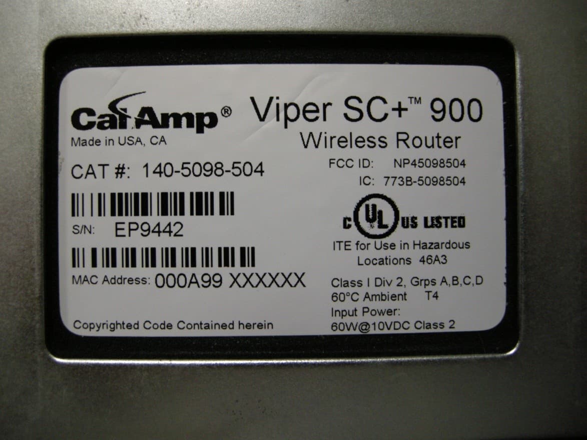
NP45098504
Sep 10, 2013Viper SC+ 928-960 MHz
Equipment Class
PCB - PCS Licensed Transmitter
NP45098304
Aug 29, 2013VIPER SC+ 900 VHF 880-902 MHZ
Equipment Class
PCB - PCS Licensed Transmitter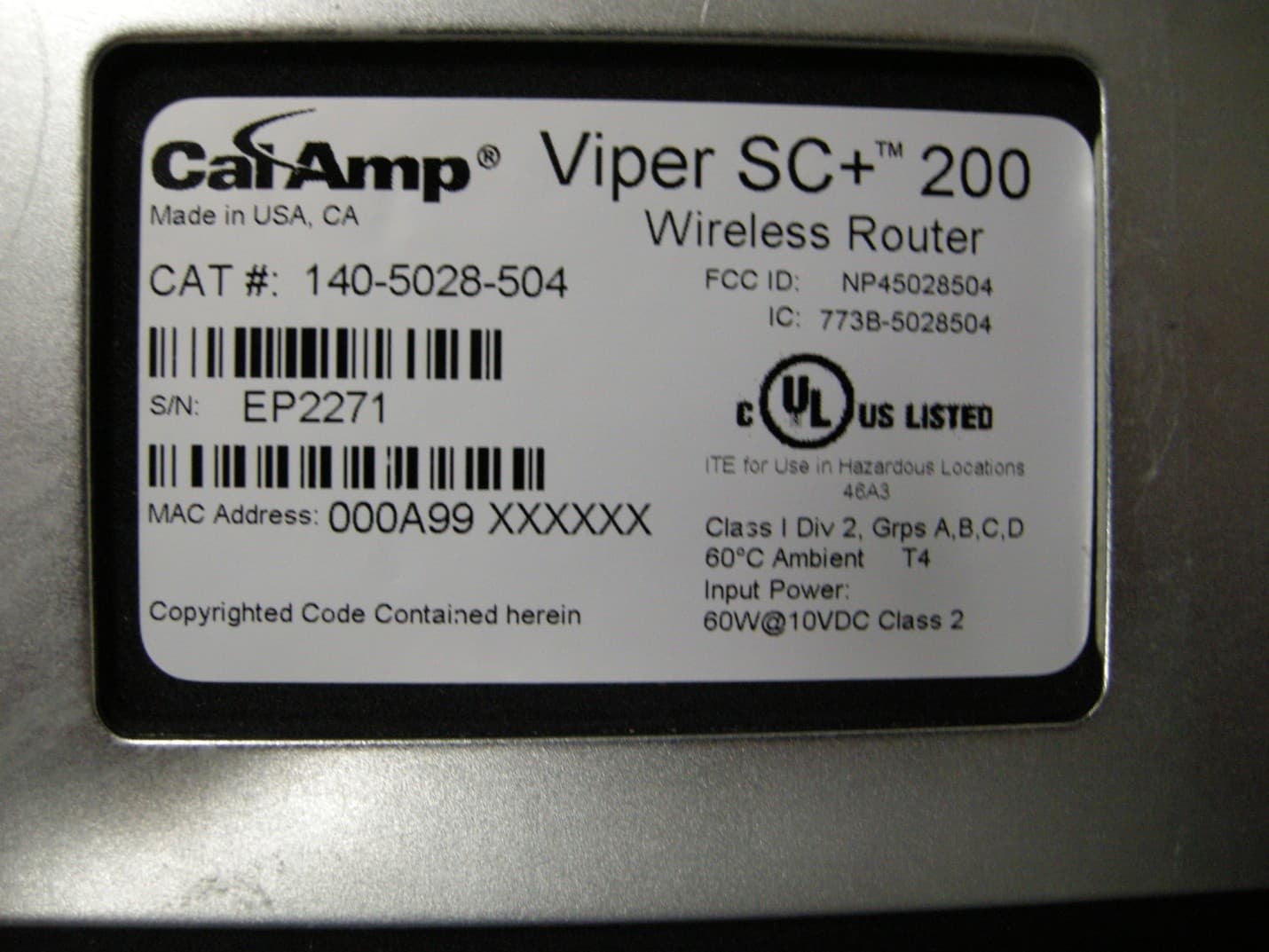
NP45028504
Aug 22, 2013VIPER SC+ 200 VHF 215-240MHZ
Equipment Class
TNB - Licensed Non-Broadcast Station Transmitter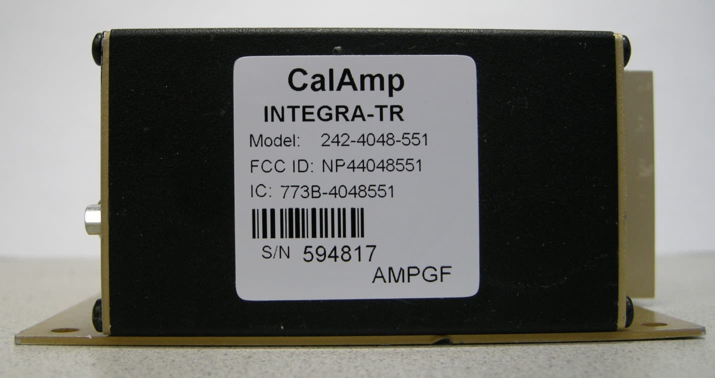
NP44048551
May 09, 2013UHF Wireless Radio Modem
Equipment Class
TNB - Licensed Non-Broadcast Station Transmitter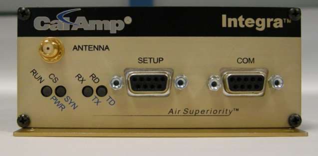
NP44048351
Apr 25, 2013UHF Wireless Radio Modem
Equipment Class
TNB - Licensed Non-Broadcast Station Transmitter