NPDR242-V01Rooftop Spread Spectrum Wireless Router
Nokia Networks Inc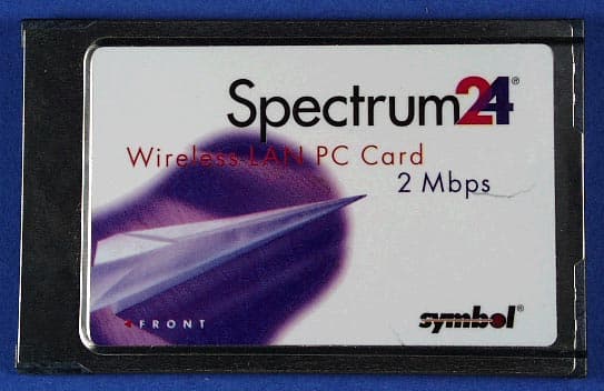
Click to zoom
Application Details
- Equipment Class
- DSS - Part 15 Spread Spectrum Transmitter
- Date of Grant
- Oct 23, 2000
- Application Purpose
- Original Equipment
- Date of Application
- Oct 23, 2000
- Equipment Note
- Rooftop Spread Spectrum Wireless Router
- Frequency Range
- 2401.00000000 - 2479.00000000
- Company
- Nokia Networks Inc
- Country
- United States
Documents & Files
Document Text
Text extracted from the exhibit documents filed with the FCC. Open a document above to read the original.
Users Manual
GSDU 468845A (paper) WREM 070700A (on CD 468846A) August, 2000 Nokia RoofTop ™ Wireless Routing Installation Guide COPYRIGHT © 2000 Nokia Corporation. All rights reserved. Rights reserved under the copyright laws of the United States. RESTRICTED RIGHTS LEGEND Use, duplication, or disclosure by the Government is subject to restrictions as set forth in subparagraph (c)(1)(ii) of the Rights in Technical Data and Computer Software clause at DFARS 252.227-7013. IMPORTANT NOTE TO USERS This device has been certified by the FCC as a Class B device and as such must be installed and/or moved by a profes- sional. TRADEMARKS Nokia is a registered trademark of Nokia Corporation. Nokia RoofTop™ is a registered trademark of Nokia Networks. Other products mentioned in this document are trademarks or registered trademarks of their respective holders. COMPLIANCE STATEMENTS This hardware complies with the standards listed in this section. Emission Standards UNINTENTIONAL EMISSIONS: FCC Part 15 CLASS B INTENTIONAL EMISSIONS: FCC Part 15, Section 15.247 This equipment has been tested and found to comply with the limits for a Class B digital device, pursuant to Part 15 of the FCC rules. These limits are designed to provide reasonable protection against harmful interference in a residential installation. This equipment generates, uses, and can radiate radio frequency energy and, if not installed and used in accordance with the instruc- tions, may cause harmful interference to radio communications. However, there is no guarantee that interference will not occur in a particular installation. If this equipment does cause harmful interference to radio or television reception which can be deter- mined by turning the equipment off and on, the user is encouraged to try and correct the interference by one or more of the fol- lowing measures: —Reorient or locate the receiving antenna. —Increase the separation between the equipment and receiver. —Connect the equipment into an outlet on a circuit different from that to which the receiver is connected. —Consult the dealer or an experienced radio/TV technician for help. Any modifications made to the unit, unless expressly approved by Nokia could void the user’s authority to operate the equip- ment. DISCLAIMER: TO THE INSTALLER: THE INSTRUCTIONS PROVIDED IN THIS GUIDE ARE PROVIDED “AS IS” WITHOUT WARRANTY OF ANY KIND EXPRESS OR IMPLIED. NOKIA MAKES NO REPRESENTATIONS OR WARRANTIES, EXPRESS OR IMPLIED, INCLUDING BUT NOT LIMITED TO THE WARRANTIES OF MERCHANTABILITY OR FITNESS FOR A PARTICULAR PUR- POSE OR INFRINGEMENT, INCLUDING ANY THIRD PARTY PATENTS, COPYRIGHTS, TRADEMARKS OR OTHER RIGHTS. THERE IS NO WARRANTY BY NOKIA THAT THE INSTRUCTIONS CONTAINED IN THE GUIDE WILL MEET YOUR REQUIREMENTS. THERE IS NO WARRANTY BY NOKIA THAT THE INSTRUCTIONS AND STATEMENTS CONTAINED IN THE GUIDE OR ITS CONTENT ARE TRUE, ACCURATE OR COMPLETE. LIMITATION OF LIABILITY: TO THE MAXIMUM EXTENT PERMITTED BY APPLICABLE LAW, IN NO EVENT SHALL NOKIA, ITS EMPLOYEES OR AFFILIATES BE LIABLE FOR ANY LOST PROFITS, REVENUE, SALES, DATA, OR COSTS OF PRO- CUREMENT OF SUBSTITUTE GOODS OR SERVICES, PROPERTY DAMAGE, PERSONAL INJURY, INTERRUPTION OF BUSINESS, LOSS OF BUSINESS INFORMATION OR FOR ANY SPECIAL, DIRECT, INDIRECT, INCIDENTAL, ECONOMIC, COVER, PUNITIVE, SPECIAL OR CONSEQUENTIAL DAMAGES HOWEVER CAUSED, AND WHETHER ARISING UNDER CONTRACT, TORT, NEGLIGENCE, OR OTHER THEORY OF LIABILITY ARISING OUT OF THE USE OF OR INABILITY TO USE THE GUIDE, EVEN IF NOKIA OR AFFILIATES ARE ADVISED OF THE POSSIBILITY OF SUCH DAMAGES. Nokia RoofTop™ Wireless Routing Installation Guidev Contents CHAPTER 1System Overview . . . . . . . . . . . . . . . . . . . . . . . . . . . . . . . 1 1.1 Introduction . . . . . . . . . . . . . . . . . . . . . . . . . . . . . 1 CHAPTER 2 Antenna Installation . . . . . . . . . . . . . . . . . . . . . . . . . . . 5 2.1 Introduction . . . . . . . . . . . . . . . . . . . . . . . . . . . . . 5 2.2 Site Analysis . . . . . . . . . . . . . . . . . . . . . . . . . . . . 6 2.2.1 RF Link Feasibility. . . . . . . . . . . . . . . . . . . . . . . . 6 2.3 Line of Sight Analysis . . . . . . . . . . . . . . . . . . . . . 8 2.3.1 Visual Line of Sight . . . . . . . . . . . . . . . . . . . . . . . 8 2.3.2 Radio Line of Sight . . . . . . . . . . . . . . . . . . . . . . . 9 2.3.3 Fresnel Zone . . . . . . . . . . . . . . . . . . . . . . . . . . . . . 9 2.3.4 Antenna Height. . . . . . . . . . . . . . . . . . . . . . . . . . . 9 2.4 Antenna Selection . . . . . . . . . . . . . . . . . . . . . . . 10 2.4.1 Omnidirectional Antennas . . . . . . . . . . . . . . . . . 10 2.4.2 Directional Antennas . . . . . . . . . . . . . . . . . . . . . 10 2.5 Cables . . . . . . . . . . . . . . . . . . . . . . . . . . . . . . . . 12 2.6 Outdoor Installation Procedures . . . . . . . . . . . . 13 2.6.1 Safety Guidelines . . . . . . . . . . . . . . . . . . . . . . . . 13 2.6.2 Required Installation Components . . . . . . . . . . . 13 2.6.3 Polarization. . . . . . . . . . . . . . . . . . . . . . . . . . . . . 14 2.6.4 Test Installation . . . . . . . . . . . . . . . . . . . . . . . . . 14 2.6.5 Grounding. . . . . . . . . . . . . . . . . . . . . . . . . . . . . . 15 2.6.6 Weatherproofing . . . . . . . . . . . . . . . . . . . . . . . . . 16 2.6.7 Weatherproofing Flexible RF Jumper Cables . . 19 2.6.8 Amplifier Weatherproofing . . . . . . . . . . . . . . . . 20 2.7 Indoor Installation Procedures . . . . . . . . . . . . . . 21 2.7.1 Weatherproofing . . . . . . . . . . . . . . . . . . . . . . . . . 21 2.7.2 Antennas . . . . . . . . . . . . . . . . . . . . . . . . . . . . . . . 21 2.7.3 Grounding. . . . . . . . . . . . . . . . . . . . . . . . . . . . . . 21 CHAPTER 3Wireless Router Installation . . . . . . . . . . . . . . . . . . 23 3.1 Introduction . . . . . . . . . . . . . . . . . . . . . . . . . . . . 23 3.1.1 Preinstallation Requirements . . . . . . . . . . . . . . . 23 viNokia RoofTop™ Wireless Routing Installation Guide Contents 3.1.2 Physic…
Text truncated - open the document above for the full version.
Users Manual
Wireless Router Subscriber Guide Bottom PanelBottom Panel Connections1. Antenna Connection: This connector connects directly to an antenna or to RF cable connected to an antenna. The connector is a TNC female connector. 2. Ethernet Interface: A standard 10/100 BaseT Ethernet jack. 3. Power Port: Connects the Nokia RoofTop Wireless Router to the 12VDC power connector. NOTE: Use only the power device provided with the unit. 4. Strain Relief: For the 12VDC power cable Connecting the Wireless Router to Your PC or LANYour wireless router is capable of providing Internet access for a single PC via adirect connection or to multiple PC’s via a local area network (LAN).Direct Connection: When connecting your wireless router to a single PC, con- nect the Ethernet port on the wireless router and the network interface on yourPC with a "crossover" Ethernet cable.LAN Connection: When connecting your wireless router to multiple PCs via a hub, router, or switch, use standard "straight-through" Ethernet cables throughoutthe entire network.NOTE: Nokia RoofTop Wireless Routers are capable of providing Internet accessfor multiple PCs, however the actual number of PCs that can receive Internetconnectivity via your wireless router will depend on the level of service you purchased from your Internet Service Provider. Technical Support Nokia provides technical support only for network operators and authorizedresellers. Technical support for subscribers to a Nokia network is provided by yourInternet Service Provider. If you experience problems with your service or haveany questions regarding the performance of your wireless router, please contactthe ISP that installed the equipment.DisclaimerNokia is the manufacturer of the wireless router and provides no warranty serviceand repair. Nokia RoofTop Wireless Routers are Provided "AS IS" with no warranty.NOKIA DISCLAIMS ALL WARRANTIES, EXPRESS OR IMPLIED, INCLUDING THEIMPLIED WARRANTY OF MECHANTABILITY AND FITNESS FOR PARTICULAR PURPOSE. NOKIA SHALL NOT BE LIABLE FOR SPECIAL, INCIDENTAL, PUNITIVE OR CONSEQUENTIAL DAMAGES, INCLUDING BUT NOT LIMITED TO LOSS OFANTICIPATED BENEFITS OR PROFITS, LOSS OF SAVINGS OR REVENUE, PUNITIVEDAMAGES, LOSS OF USE OF THE PRODUCT OR ANY ASSOCIATED EQUIPMENT,COST OF CAPITAL, COST OF ANY SUBSTITUTE EQUIPMENT OR FACILITIES, DOWN-TIME, THE CLAIMS OF ANY THIRD PARTIES, INCLUDING CUSTOMERS, AND INJURYTO PROPERTY, RESULTING FROM THE PURCHASE OR USE OF THE PRODUCT ORARISING FROM BREACH OF THE WARRANTY, BREACH OF CONTRACT, NEGLIGENCE,STRICT TORT, OR ANY OTHER LEGAL OR EQUITABLE THEORY, EVEN IF NOKIAKNEW OF THE LIKELIHOOD OF SUCH DAMAGES. NOKIA SHALL NOT BE LIABLEFOR DELAY IN RENDERING SERVICE UNDER THE LIMITED WARRANTY, OR LOSSOF USE DURING THE PERIOD THAT THE PRODUCT IS BEING REPAIRED.If you experience any problem or malfunction of the wireless router, please contact the ISP that installed the equipment. COPYRIGHT© 2000 Nokia Corporation. All rights reserved.Rights reserved under the copyright laws of the United States.RESTRICTED RIGHTS LEGENDUse, duplication, or disclosure by the Government is subject to restrictions as set forth in subparagraph (c)(1)(ii) of the Rights in Technical Data and Computer Software clause at DFARS 252.227-7013.TRADEMARKSNokia and Nokia RoofTop are registered trademarks of Nokia Corporation.Other products mentioned in this document are trademarks or registered trademarks of their respective holders. REGULATORY INFORMATIONThis equipment has been tested and found to comply with the limits for a Class B digital device, pursuant to Part 15 of the FCC rules. These limits are designed to provide reasonable protectionagainst harmful interference in a residential installation. This equipment generates, uses, and canradiate radio frequency energy and, if not installed and used in accordance with the instructions, may cause harmful interference to radio communications. However, there is no guarantee that interference will not occur in a particular installation. The antennas used for this transmitter may not This equipment must be installed by a professional installer. End User Card Comp 1-REV 8/4/00 1:51 PM Page 1 Service Only by Qualified ServicePersonnel• Do not open the unit, reconfigure the software or change power supplies. • The user should not make any attempt to service the wireless router.• The unit should be serviced only by qualified service personnel.Front PanelFront Panel ViewThe front panel indicators provide a quick check of the status of the wirelessrouter and its connections. The LEDs are labeled from left-to- right as follows: 1. Ethernet LAN - shows the local area network activity. 2. Radio - shows both transmit and receive radio activity. 3. Anchor - shows status in network and gives RF link information. If this light is off you do not have the connectivity to the network. 4. Power Indicator - Steady light indicates the unit is powered on. Introduction Your Nokia RoofTop™ Wireless Router is a revolutionary new product, deliveringhigh-speed wireless Internet access. Nokia RoofTop Wireless Routers combine an RF modem with a digital IP router board and specialized wireless routing system, the Nokia AIR Operating System(OS). This combination creates an IP router that is “wireless and intelligent.”Your Nokia RoofTop Wireless Router not only provides you with fast “always-on”Internet access, but is also an integral part of the network infrastructure. Somerouters may rely on others to reach the Internet. It is very important that yourwireless router is always powered ON, even when you are not using it, as it maybe forwarding and routing traffic for other routers in the network. Warnings, Safety Instructionsand Technical SupportImportant User InformationThe Nokia RoofTop Wireless Router was designed and manufactured to meetstrict quality and safety standards. It complies with the FCC rules, Part 15 andwith 21 CFR 1040.10 and 1040.11.This wireless router and its associated components are Class B devices that must b…
Text truncated - open the document above for the full version.
External Photos
Detailed External Photographs The following external photographs are contained in this file: å Main unit å Amplifier and DC Injector å PCMCIA Card ( PCMCIA card purchased from Symbol. The PCMCIA card was approved by Symbol under FCC ID H9PLA3021) Main Unit External Photographs DC-injector External Photographs Amplifier External Photographs External Photographs – Symbol Wireless LAN PCMCIA Card External Views – Front And Back
ID Label/Location Info
LABEL, R242(A)1 (2) NET/RAS/NWR14/07/2000 Generic label: Made in the USA Label for USA: Nokia RoofTop Wireless Router Model No: R242A Type: FH1 FCC ID: NPD-R242-V01 This device complies with Part 15 of the FCC Rules. FFYYWWNNNNN Operation is subject to the following two conditions: (1) This device may not cause harmful interference, And (2) This device must accept any interference received, including interference that may cause undesired operation SSSSSSSS......VCC Made in the USA Where: FFYYWWNNNNN, is factory, year, week, serial number, according to Nokia instructions. (Pemstar factory code is J3) SSSSSSS......VCC, is product code and version, according to Nokia instructions, Model Number is R242 for a Subscriber Unit, and R242A for an AirHead. Type can vary depending on the standards in different countries. Label is to be permanently glued to product. Max. 36 mm Max. 75 mm LABEL, R242(A)2 (2) NET/RAS/NWR14/07/2000 Label Located Here Back Side of Product
Internal Photos
Detailed Internal Photographs The following internal photographs are contained in this file: å Main unit å Amplifier and DC Injector å PCMCIA Card ( PCMCIA card purchased from Symbol. The PCMCIA card was approved by Symbol under FCC ID H9PLA3021) Main Unit Internal Photograph DC-injector Internal Photographs Amplifier Internal Photographs Internal Photographs –Symbol Wireless LAN PCMCIA Card Bottom Of Card With And Without Shields Top Of Card With And Without Shields
RF Exposure Info
Addendum to Theory of Operations for Nokia FHSS Radio – MPE Calculation The radio can be configured with and without an external amplifier with 6dBi gain. With the amplifier in place, ignoring loss of cables, the maximum output power is 29dBm. Without the amplifier in place the maximum output power, neglecting cable loss, is 24.4dBm. With the external amplifier, the maximum gain antenna that can be used is an 8dBi Omni antenna. Without the amplifier the maximum antenna gain is 17dBi. The combination of 17dBi antenna and un-amplified output gives the highest EIRP possible from the system. This EIRP, 41.4Bm, will be used to determine the MPE “safe” distance. FCC part 1.1310, Table 1 limits the power density for uncontrolled exposure to 1mW/cm 2 . The distance, d(cm) from the antenna at which the power density, Pd (mW/cm 2 ) is below this limit is calculated from the transmit power, Pt (mW) and Antenna Gain (G) using the equation: Pd = Pt G 4πd 2 Re-arranging for the distance at which the power density is 1mW/cm 2 gives: d 2 = Pt G 4π So, the minimum separation that must be maintained from the antenna to ensure the rf exposure limits are not exceeded are: For an un-amplified system with an EIRP of 41.4dBm (13803mW): 33.1 cm The Nokia user’s manual and installation guide both reference a safe distance to ensure this separation. The User Guide contains the following statement: RF Exposure – Disconnect power from the wireless router when working within 2 meters of the antenna. The Installation Manual contains the following statement on page 3: THE ANTENNA FOR THIS TRANSMITTER MUST BE INSTALLED TO PROVIDE A SEPARATION DISTANCE OF 2 METERS OR MORE FROM PERSONS TO ENSURE COMPLIANCE WITH EXPOSURE GUIDELINES.
Test Report
Engineer: MbirganiManufacturer Description Model # Assett # Cal interval Last Calibrated Cal Due EMCO D. Ridge Horn Antenna, 1-18GHz 3115 487 12 3/24/00 3/24/01 Hewlett Packard EMC Spectrum Analyzer, Opt. 026 ̨9 KHz -26.5GHz 8593EM 1141 12 12/22/99 12/22/00 Hewlett Packard Microwave Preamplifier, 1-26.5GHz 8449B 870 12 11/15/99 11/15/00 Engineer: VishalManufacturer Description Model # Assett # Cal interval Last Calibrated Cal Due Hewlett Packard Spectrum Analyzer, 9kHz - 26.5 GHz 8363E 284 12 2/26/00 1/26/01 Engineer: DavidManufacturer Description Model # Assett # Cal interval Last Calibrated Cal Due Elliott Laboratories Fischer LISN-2 + 2 (Solar 8028 + 6512 Cap) LISN-1, Screen Room 198 12 11/11/99 11/11/00 Hewlett Packard Spectrum Analyzer, Display Section 85662A 43 12 6/29/99 6/29/00 Hewlett Packard Spectrum Analyzer, Quasi Peak Adapter 85650A 42 12 3/24/00 3/24/01 Hewlett Packard Spectrum Analyzer, RF Section 85680B 44 12 6/29/99 6/29/00 Solar Electronics High Pass Filter, fc = 8 kHz 7930-8.0 223 12 7/26/99 7/26/00 Radiated Emissions, 2.4 - 24.0 GHz, 15-Jun-00Conducted Emissions, 22-Jun-00 12:55 PMAntenna Conducted Emissions, 19-Jun-00 File: T38016 Test Equipment (Emissions) 1 of 1 Engineer: tbanhManufacturer Description Model # Assett # Cal interval Last Calibrated Cal Due EMCO D. Ridge Horn Antenna, 1-18GHz 3115 868 12 9/25/99 9/25/00 Hewlett Packard EMC Spectrum Analyzer, Opt. 026 ̨9 KHz -26.5GHz 8593EM 1141 12 12/22/99 12/22/00 Hewlett Packard Microwave Preamplifier, 1-26.5GHz 8449B 785 12 12/2/99 12/2/00 Narda West EMI Filter 5.6 GHz, High Pass 60583 HXF370 247 12 3/27/00 3/27/01 Engineer: PamelaManufacturer Description Model # Assett # Cal interval Last Calibrated Cal Due Rohde& Schwarz Pulse Limiter ESH3 Z2 812 12 12/6/99 12/6/00 Rohde & Schwarz Test Receiver, 0.009-30 MHz ESH3 215, (F197) 12 2/17/00 2/17/01 Solar Support LISN 904 12 2/28/00 2/28/01 Elliott Laboratories LISN 362 12 3/17/00 3/17/01 Radiated Emissions, 1 - 6.5 GHz, 18-Jul-00 03:06 AMConducted Emissions, 20-Jul-00 10:16 PM File: T38457 Test Equipment (Emissions) 1 of 1
Test Report
Spectrum Analyzer Plots Test Log File T38016
Test Report
Spectrum Analyzer Plots Test Log File T38457
Test Report
File: R38142 July 27, 2000 American Telecommunications Certification Body, Inc 6731 Whittier Avenue McLean, VA. 22101 Gentlemen: The enclosed documents constitute a formal submittal and application for a Grant of Equipment Authorization pursuant to Subpart C of Part 15 of FCC Rules (CFR 47) regarding intentional radiators. Data within this report demonstrates that the equipment tested complies with the FCC limits for intentional radiators. Elliott Laboratories, as duly authorized agent prepared this submittal. A copy of the letter of our appointment as agent is enclosed. If there are any questions or if further information is needed, please contact Elliott Laboratories for assistance. Sincerely, Mark R. Briggs Manager, EMC Consulting Services MRB/dmg Enclosures: Agent Authorization Letter Emissions Test Report with Exhibits Confidentiality Request Manufacturer’s Letter FCC Labeling Requirements Letter File: R38142 Page 1 of 18 Electromagnetic Emissions Test Report and Application for Grant of Equipment Authorization pursuant to FCC Part 15, Subpart C Specifications for an Intentional Radiator on the Nokia Networks Model: Presidio FCC ID: NPD-R242-V01 GRANTEE: Nokia Networks Nokia Networks Mountain View, CA. 94043 TEST SITE: Elliott Laboratories, Inc. 684 W. Maude Avenue Sunnyvale, CA 94086 REPORT DATE: July 27, 2000 FINAL TEST DATE: June 15, June 19, June 22 and July 20, 2000 AUTHORIZED SIGNATORY: ______________________________ Mark R. Briggs Manager, EMC Consulting Services This report shall not be reproduced, except in its entirety, without the written approval of Elliott Laboratories, Inc. Elliott Laboratories, Inc. -- EMC Department Test Report Report Date: July 27, 2000 File: R38142 Page 2 of 18 pages TABLE OF CONTENTS COVER PAGE..................................................................................................................................................................................1 TABLE OF CONTENTS...............................................................................................................................................................2 SCOPE.............................................................................................................................................................................................4 OBJECTIVE...................................................................................................................................................................................4 STATEMENT OF COMPLIANCE..............................................................................................................................................4 EMISSION TEST RESULTS.......................................................................................................................................................5 LIMITS OF CONDUCTED INTERFERENCE VOLTAGE....................................................................................................5 LIMITS OF ANTENNA CONDUCTED SPURIOUS EMISSIONS – PRESIDIO WITHOUT AMPLIFIER....................5 LIMITS OF ANTENNA CONDUCTED SPURIOUS EMISSIONS – PRESIDIO WITH AMPLIFIER............................5 LIMITS OF POWER AND BANDWIDTH – PRESIDIO WITHOUT AMPLIFIER..........................................................5 LIMITS OF POWER AND BANDWIDTH – PRESIDIO WITH AMPLIFIER...................................................................6 CHANNEL OCCUPANCY TESTS..........................................................................................................................................6 LIMITS OF RADIATED INTERFERENCE FIELD STRENGTH.........................................................................................6 MEASUREMENT UNCERTAINTIES....................................................................................................................................7 EQUIPMENT UNDER TEST (EUT) DETAILS..........................................................................................................................8 GENERAL...................................................................................................................................................................................8 ENCLOSURE..............................................................................................................................................................................9 MODIFICATIONS....................................................................................................................................................................9 SUPPORT EQUIPMENT........................................................................................................................................................10 EUT INTERFACE PORTS......................................................................................................................................................10 EUT OPERATION...................................................................................................................................................................10 TEST SITE....................................................................................................................................................................................11 GENERAL INFORMATION..................................................................................................................................................11 CONDUCTED EMISSIONS CONSIDERATIONS..............................................................................................................11 RADIATED EMISSIONS CONSIDERATIONS..................................................................................................................11 MEASUREMENT INSTRUMENTATION................................................................................................................................12 RECEIVER SYSTEM..............................................…
Text truncated - open the document above for the full version.
Test Setup Photos
Elliott Laboratories, Inc. -- EMC Department Test Report Report Date: July 27, 2000 File: R38142 Appendix Page 3 of 15 EXHIBIT 3: Radiated Emissions Test Configuration Photographs Sector Antenna Elliott Laboratories, Inc. -- EMC Department Test Report Report Date: July 27, 2000 File: R38142 Appendix Page 4 of 15 EXHIBIT 3: Radiated Emissions Test Configuration Photographs Panel Antenna Elliott Laboratories, Inc. -- EMC Department Test Report Report Date: July 27, 2000 File: R38142 Appendix Page 5 of 15 EXHIBIT 3: Radiated Emissions Test Configuration Photographs Omni Antenna Elliott Laboratories, Inc. -- EMC Department Test Report Report Date: July 27, 2000 File: R38142 Appendix Page 6 of 15 EXHIBIT 4: Conducted Emissions Test Configuration Photographs System Without Amplifier Elliott Laboratories, Inc. -- EMC Department Test Report Report Date: July 27, 2000 File: R38142 Appendix Page 7 of 15 EXHIBIT 4: Conducted Emissions Test Configuration Photographs System Without Amplifier Elliott Laboratories, Inc. -- EMC Department Test Report Report Date: July 27, 2000 File: R38142 Appendix Page 8 of 15 EXHIBIT 4: Conducted Emissions Test Configuration Photographs System With Amplifier Elliott Laboratories, Inc. -- EMC Department Test Report Report Date: July 27, 2000 File: R38142 Appendix Page 9 of 15 EXHIBIT 4: Conducted Emissions Test Configuration Photographs System With Amplifier
Contact Information
Applicant
Nico Van Waes(Systems Engineer)
Test Firm
Elliott Laboratories LLCDavid Bare
Technical Specifications
| # | Rule Parts | Frequency Range | Power Output |
|---|---|---|---|
| 1 | 15C | 2.40 GHz - 2.48 GHz | 830.00 mW |
Other Applications from Nokia Networks Inc
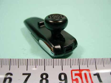
NPDUBH-2010
Jun 29, 2005BLUETOOTH HEADSET
Equipment Class
DSS - Part 15 Spread Spectrum Transmitter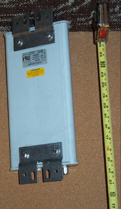
NPD-R240-V01
May 15, 2001FHSS ODU and IDU
Equipment Class
DSS - Part 15 Spread Spectrum Transmitter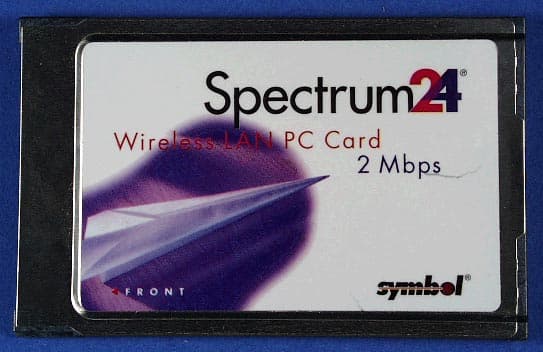
NPD-R242-V02
Jan 30, 2001frequency-hopping spread spectrum (FHSS) transceiver
Equipment Class
DSS - Part 15 Spread Spectrum TransmitterNPDSP-104
Mar 31, 1998LAN Transmitter Module Max. Output Power 68 milliwatts
Equipment Class
DSS - Part 15 Spread Spectrum Transmitter