NPI43448Remote Control for Toy
LEGO Systems Inc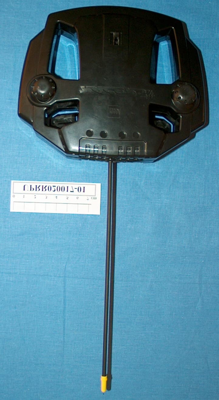
Click to zoom
Application Details
- Equipment Class
- DXX - Part 15 Low Power Communication Device Transmitter
- Date of Grant
- May 28, 2002
- Application Purpose
- Original Equipment
- Date of Application
- May 28, 2002
- Equipment Note
- Remote Control for Toy
- Frequency Range
- 27.14500000 - 27.14500000
- Company
- LEGO Systems Inc
- Country
- Denmark
Documents & Files
Document Text
Text extracted from the exhibit documents filed with the FCC. Open a document above to read the original.
Users Manual
Model: RC Race Buggy transmitter (43448) FCC ID: NPI43448 This device complies with part 15 of the FCC Rules. Operation is subject to the following 2 conditions: 1. This device may not cause harmful interference. 2. This device must accept any interference received including interference that may cause undesired operation. Cet appareil est conforme aux exigences de la section 15 des règlements du Conseil supérieur de l'audiovisuel (FCC). Son fonctionnement ast soumis aux 2 conditions qui suivent: 1. Cet appareil ne peut causer de brouillage nocif. 2. Cet appareil doit accepter tout brouillage reçu, y compris le brouillage pouvant engendrer un code d'opération non souhaité. Warning: Changes or modifications to this unit not expressly approved by the party responsible for compliance could void the user's authority to operate the equipment. Avertissement: Les changements ou modifications apportés à cette unité et n'ayant pas été expressément autorisés par l'équipe responsible de la conformité aux règlements pourraient annuler la permission accordée à l'utilisateur quant à l'opératuib de l'équipement. 4191490 NOTE: This equipment has been tested and found to comply with the limits for a Class B digital device, pursuant to part 15 of the FCC Rules. These limits are designed to pro-vide reasonable protection against harmful interference in a residential installation. This equipment generates, uses an can radi-ate radio frequency energy and, if not in-stalled and used in accordance with the in-structions, may cause harmful interference to radio communications. However, there is no guarantee that interference will not occur in a particular installation. If this equip-ment does cause harmful interference to radio or television reception, which can be determined by turning the equipment off and on, the user is encouraged to try to correct the interference by one or more of the fol-lowing measures: * Reorient or relocate the receiving antenna. * Increase the separation between the equip-ment and receiver. * Connect the equipment into an outlet on a circuit different from that to which the receiver is connected. Consult the dealer or an experienced radio/ TV technician for help. REMARQUE :Cet équipement a été testé et déclaré conforme aux limites définies dans la section 15 de la réglementation FCC et applicables aux appareils numériques de classe B. Ces limites sont fixées pour obtenir une protection satisfaisante contre les interférences nuisibles dans les installations résidentielles. Cet équipement produit, consomme et peut émettre de l’énergie radioélectrique et il risque, s’il n’est pas installé et utilisé conformément aux instructions, de provoquer des interférences nuisibles avec les communications radio. Il est cependant impossible de garantir que des interférences ne surviendront pas dans une installation particulière. Si cet équipement est la cause d'interférences gênant la réception de programmes radio ou télévisés, ce qui peut être déterminé en mettant l'appareil hors tension et de nouveau sous tension, il est demandé à l'utilisateur de tenter de remédier au problème à l'aide d'une ou plusieurs des mesures suivantes : * Réorienter ou déplacer l'antenne de réception. * Augmenter la distance séparant l'équipement et le récepteur. * Raccorder l'équipement sur une sortie appartenant à un circuit différent de celui auquel le récepteur est connecté. Consulter le revendeur ou un technicien radio-télévision expérimenté pour obtenir de l’aide.
Block Diagram
Prepared by: Dan Bach Olesen, Lego Technology Center 25-04-2002 Technic Racer Block diagram: The picture above shows the block diagram of the Technic Racer. Transmitter Unit: The transmitter unit is operating on a 9V battery. The modulated data is sent to the 27.145 MHz AM transmitter. The transmitter have two control handles (forward/reverse and left/right). Beside it also have a on/off control for the 1A motordriver. Receiver Unit: The receiver unit is operating on 6xAA batteries (9V). The received data from the super regenerativc receiver is sent to the MCU. The MCU then controls the 3 different motors. The steering motordriver is the same as the 1A motordriver. The two small motordrivers is integrated motordrivers with thermal and overcurrent protection and the 5A driver is a discrete H-bridge with overcurrent protection. 5A Motordriver MCU @ 4MHz Technic Racer Block diagram Transmitter Unit (43448) 1 1 A Block diagram DBO SCHEMATIC1 <Drafter> <Version> <DraftDate> <ProjectNumber> 25-04-2002 of Title Project Number Engineer/constructer Schematic Name Date (YYYY/MM/DD) DrafterDate (YYYY/MM/DD) Sheet Page Size Version J1 12 Receiver unit (43445) MCU @ 3.58MHz 27.145MHz AM transmitter ANTENNA ANTENNA Steering motordriver 1A Motordriver J2 12 Super regenerative receiver
Cover Letter(s)
American Telecommunications Certification Body Inc. 6731 Whittier Ave, McLean, VA 22101 April 26, 2002 RE: FCC ID: NPI43448 I have a few comments on this Application. Please note that this device is not compliant with the FCC rules. See item 6 below for explanation. 1 The internal photos are not complete. There are two devices on either side of the main board that have PC boards in them. Please remove the covers on these devices and take photos of the circuit boards (both top and bottom). Also, please show the inside of the main housing in relation to the other components. x 2 There appears to be an antenna in the external photo, yet this does not appear in the internal photos. Please show this antenna as it is connected to the internal circuit boards. x 3 The label appears to be sufficiently large enough to contain the two condition statement. Please explain why this statement is not on the label. Please use the label specifications described in 15.19 (All other devices shall bear the following statement in a conspicuous location ON THE DEVICE: “This device complies with Part 15 of the FCC Rules. Operation is subject to the following two conditions: (1) this device may not cause harmful interference, and (2) this device must accept any interference received, including interference that may cause undesired operation.” Only when the device is too small can this statement be placed in the manual. Please note, this device nor the label is too small. Consequently, this statement should appear on the label on the device. x 4 The report uses conflicting technical information. Report Section 3.1 states the device a single channel device is operating at 27.128MHz. Report Section 3.2 and the manual state the device is a 10 mw single channel device operating at 27.145 MHz. The 731 and the schematics indicate that the device operates at 27.145MHz. The schematic also indicates there is a multiple channel switch capability. Please correct the conflicting information between the report and schematic. Please note that the reference to Also, if this device uses multiple channel frequencies please state what those frequencies are. x 5 The report states that measurements below 30 MHz was done in according to 8.2.3 of ANSI C63.4. Please note that 8.2.3 is for measurements ABOVE 30 MHz, not below. Also, please note that the FCC does not accept clause 8.2.2 use of a rod antenna. It is FCC policy to require that measurements below 30 MHz be done with a loop antenna. x 6 For intentional radiators 15.209 states, “....the level of any unwanted emissions shall not exceed the level of the fundamental frequency.” Please note that on pages 6 & 9 of the report 624.3 MHz exceeds the level of the fundamental by more than 7dB. This device is therefore not compliant with the intentional radiator rules. Please re-measure and/or correct the device to be in compliance. xx 7 Please note that your statement in section 5.3.1 is incorrect. While 15.33 states that intentional radiators are to be tested to AT LEAST the tenth harmonic, 15.33 also states, “If the intentional radiator contains a digital device, regardless of whether this digital device controls the functions of the intentional radiator or the digital device is used for additional control or function purposes other than to enable the operation of the intentional radiator, the frequency range shall be investigated up to the range specified in paragraphs (a)(1) through (a)(3) of this section or the range applicable to the digital device, as shown in paragraph (b)(1) of this section, whichever is the higher frequency range of investigation.” Please correct this statement. x l Page 2April 26, 2002 8 Please note that the FCC requires the entire manual that will be provided to the end user to be provided as part of an application. Please provide the full manual for review. x manual too large. 9 Your manual insert states the device is a Part 15 Class A. Please note that since this is a ‘game’ or toy device and since no other evidence to the contrary indicates its use outside of a home environment, the FCC views this as a class B digital device for use in the home environment. As such, the information to the user specified in 15.105 must be placed in the manual. x Dennis Ward mailto:[email protected] The items indicated above must be submitted before processing can continue on the above referenced application. Failure to provide the requested information may result in application termination. Correspondence should be considered part of the permanent submission and may be viewed from the Internet after a Grant of Equipment Authorization is issued. Please do not respond to this correspondence using the email reply button. In order for your response to be processed expeditiously, you must submit your documents through the AmericanTCB.com website. Also, please note that partial responses increase processing time and should not be submitted. Any questions about the content of this correspondence should be directed to the sender.
Cover Letter(s)
Subject: SV: Npi43448 request for info Date: Fri, 3 May 2002 14:09:32 +0200 From: Martin Bülow Arndt <[email protected]> To: 'Dennis Ward' <[email protected]> Dear Dennis I will hereby try to clear most of the outstanding issues with regard to application NPI43448. 1. Additional photos of other PCB's. Additional photos has been uploaded see file "additional photos" 2. Additional photos of antenna connection. Additional photos has been uploaded, see file "additional photos" 3. The customer is currently looking to find a solution. 4. The frequency given in section 3.1 is due to a typing error and the switch do not change the frequency of the device but the code send to the receiver. The report has been corrected as appropriate. See draft report attached. 5. The measurements will be repeated using a loop antenna next week. Is the method to be used clause 8.2.1 in ANSI 63.4? 6. In the pre-scan it is shown that the level of the fundamental is approx. 15 dB higher than the level at 624.3 MHz when using the SAME TYPE of detector (peak). Is it the intention of clause 15.209 to compare levels obtained with avg. and QP detectors? As mentioned under point 5 (above) the fundamental will be re-measured with the loop antenna. This change of measurement method might give a different result bring an end to this problem. 7. Calculation of frequency range. The report has been changed to give the exact reason for performing measurements to 1000MHz. See draft report attached. 8. A complete manual will be uploaded shortly. 9. The manual will be changed to include the information of the manual insert. The reference to 15 part A is a mistake and will be deleted. I see the product as a remote control and NOT as a digital device. Is it necessary to include both the text of 15.19 and 15.105 on the product / in the manual? I guess that this clears your comment number 1, 2, 4 and 7. Based on your comments to my questions above, the remaining problems will be solved shortly. Section 4, 6 and 7 of the draft report will be changed when the new loop measurement has been performed. <<Draft report.doc>> Best regards Martin Bülow Arndt Telelaboratoriet TDC Mobil A/S Phone: +45 43 34 5522 / Fax +45 43 528571 E-Mail: [email protected] Internet: http://www.telelaboratoriet.dk -----Oprindelig meddelelse----- Fra: Dennis Ward [SMTP:[email protected]] Sendt: 27. april 2002 01:10 Til: Martin Bülow Arndt Emne: Npi43448 request for info Hi Martin The attached is a request for inforamation on the above ID. I must inform you that the device is not in compliance with the FCC Rules. Please note all items correct as encessary - especially item 6. Thanks Dennis Ward [email protected] <<Fil: 4-26-02 Npi43448 request for info.PDF>> --------------------------------------------------------------------- Name: Draft report.doc Draft report.doc Type: Microsoft Word Document (application/msword) Encoding: base64
Cover Letter(s)
Subject: SV: NPI43448 grant Date: Thu, 30 May 2002 09:38:02 +0200 From: Martin Bülow Arndt <[email protected]> To: 'Dennis Ward' <[email protected]> Hi Dennis Thanks a lot for the quick response and return of the grant. The Pre-amp figure on page 9 is taken into account when calculating the final results. The value is only shown in order to reproduce the measurement correctly if necessary. I can confirm that the test is performed in tree orthogonal planes and that final values represent the worst case emission levels. Best Regards Martin Bülow Arndt Telelaboratoriet TDC Mobil A/S Phone: +45 43 34 5522 / Fax +45 43 528571 E-Mail: [email protected] Internet: http://www.telelaboratoriet.dk -----Oprindelig meddelelse----- Fra: Dennis Ward [SMTP:[email protected]] Sendt: 30. maj 2002 03:16 Til: Martin Bülow Arndt Emne: NPI43448 grant Hi Martin Well here it is finally. the grant for the above ID is attached. One last question, in the Report, while you mention a 10dB preamp factor, it is not clear if this factor is calculated into the final number. See page 9of 11 in the report. Please verify that this is the case. thanks Dennis Ward [email protected] <<Fil: NPI43448 grant.pdf>> Subject: [Fwd: NPI43448 grant] Date: Wed, 29 May 2002 18:31:50 -0700 From: Dennis Ward <[email protected]> Organization: dt Associates To: [email protected] Hi Martin Please also verify that all three orthogonal planes were tested with this device. thanks Dennis [email protected]
External Photos
Lower cover including connection form main board to antenna (small black wire) Upper cover Speed control (additional PCB) Steering control (additional PCB)
ID Label/Location Info
Indentification Label for the LEGO Technic Racer Transmitter 43448: The label for FCC and CE will be placed inside the white marking below. Please note that the text will be engraved in the plastic, so it will be a non removable "label". Size: 50x20 mm. Place: Back of transmitter. Identification Label design: The label will have following design (see below). LABEL 27.145 MHz0189 FCC ID: NPI43448 This equipment complies with the requirements in Part 15 of FCC Rules. See manual. !
ID Label/Location Info
Identification Label for the LEGO Technic Racer Transmitter 43448 The text of the label for FCC and CE will be as shown below. The label will be placed on the back of the equipment, as shown below. NOTE: Due to the necessary size of the battery cover plate, holes for screws and the mechanical layout of the product it is impossible to place the complete warning of §15.19 on the product. Reference to this warning is made on the label, and the complete text of §15.19 is placed in the manual.
Internal Photos
Lower cover including connection form main board to antenna (small black wire) Upper cover Speed control (additional PCB) Steering control (additional PCB)
Operational Description
Prepared by: Dan Bach Olesen, Lego Technology Center 25-04-2002 Technic Racer Block diagram: The picture above shows the block diagram of the Technic Racer. Transmitter Unit: The transmitter unit is operating on a 9V battery. The modulated data is sent to the 27.145 MHz AM transmitter. The transmitter have two control handles (forward/reverse and left/right). Beside it also have a on/off control for the 1A motordriver. Receiver Unit: The receiver unit is operating on 6xAA batteries (9V). The received data from the super regenerativc receiver is sent to the MCU. The MCU then controls the 3 different motors. The steering motordriver is the same as the 1A motordriver. The two small motordrivers is integrated motordrivers with thermal and overcurrent protection and the 5A driver is a discrete H-bridge with overcurrent protection. 5A Motordriver MCU @ 4MHz Technic Racer Block diagram Transmitter Unit (43448) 1 1 A Block diagram DBO SCHEMATIC1 <Drafter> <Version> <DraftDate> <ProjectNumber> 25-04-2002 of Title Project Number Engineer/constructer Schematic Name Date (YYYY/MM/DD) DrafterDate (YYYY/MM/DD) Sheet Page Size Version J1 12 Receiver unit (43445) MCU @ 3.58MHz 27.145MHz AM transmitter ANTENNA ANTENNA Steering motordriver 1A Motordriver J2 12 Super regenerative receiver
Test Report
Telelaboratoriet Test Report UPRR020023-01Page 2 of 7 Title: Test on LEGO, RACERS remote control for toy, to FCC Part 15C clause 15.227. Telelaboratoriet CONTENTSPAGE 1.TEST SPECIFICATION AND METHODS....................................................................3 2.LOCATION OF TEST SITE.............................................................................................3 3.EUT DESCRIPTION........................................................................................................4 3.1.General.....................................................................................................................4 3.2.Technical specifications.....................................................................................4 4.DEVIATIONS OR EXCLUSIONS FROM THE TEST SPECIFICATIONS..............4 5.TESTS AND TEST CONDITIONS.................................................................................5 5.1.EUT ports to be examined..................................................................................5 5.2.Operation of the EUT............................................................................................5 5.3.Limits and frequency ranges used...................................................................5 6.MEASUREMENTS, EXAMINATIONS AND DERIVED RESULTS.........................5 6.1.Test results, Emission.........................................................................................6 7.LIST OF INSTRUMENTS................................................................................................7 Annexes: 1 – 2:RF emissions / Radiated emission (Pre-scan + Final) 3 – 4:Photos of test set-up Telelaboratoriet Test Report UPRR020023-01Page 3 of 7 Title: Test on LEGO, RACERS remote control for toy, to FCC Part 15C clause 15.227. Telelaboratoriet 1. Test Specification and Methods Purpose of Test:The tests are performed in order to demonstrate compliance with the FCC requirements for intentional transmitters operating in the freq. range 26,96 – 27,28MHz. Test Specifications: Limits: [1]CFR 47 Part 15: 2001, Code of Federal Regulation 47 (Telecommunication), Part 15 (Radio Frequency Devices), Subpart C (Intentional Radiators) Clause 15.227 and 15.209 Methods and Procedures: The Test methods and procedures are defined in the following standard(s) (for undated references the latest edition applies): [2]ANSI C63.4 : 2000, American National Standard for Methods of Measurement of Radio-Noise Emissions form Low-Voltage Electrical and Electronic Equipment in the Range of 9 kHz to 40 GHz 2. Location of Test Site Test are performed at the test site of Tele Danmark A/S (Telelaboratoriet) at the address: Tele Danmark A/S (Telelaboratoriet) Telegade 2 DK-2630 Taastrup Denmark This site is listed at the FCC under the Registration Number 92797 since December 19, 2001. Telelaboratoriet Test Report UPRR020023-01Page 4 of 7 Title: Test on LEGO, RACERS remote control for toy, to FCC Part 15C clause 15.227. Telelaboratoriet 3. EUT Description 3.1. General The EUT is a single channel RF remote control operating at 27,145 MHz band. Model: Racers Type: 44278 Manufacture: LEGO Systems A/S Åstvej 1 DK-7190 Billund Denmark 3.2. Technical specifications Frequency:27,128 MHz Number of channels:1 (simplex) Type of modulation:AM TX power (EIRP):10dBm / 10 mW Antenna type:Internal Antenna gain(rated):- Power supply:9 VDC Type of equipment:Short Range Device Temperature range:-10 – +55 deg. C. 4. Deviations or Exclusions from the Test Specifications Emission measurements in the range below 30MHz (27 – 30 MHz) are made with a Biconical antenna according to clause 8.2.3 in ANSI 64.3:2000. The Biconical antenna has AF calibration values starting at 20MHz. Telelaboratoriet Test Report UPRR020023-01Page 5 of 7 Title: Test on LEGO, RACERS remote control for toy, to FCC Part 15C clause 15.227. Telelaboratoriet 5. Tests and test conditions 5.1. EUT ports to be examined Following port was examined during the tests: 1. Enclosure port 5.2. Operation of the EUT During the radiated emission testing the EUT controls were activated to generate a constant RF transmission at 27,145MHz. An internal battery (9V alkaline cell) powered EUT during testing. 5.3. Limits and frequency ranges used 5.3.1. Enclosure port measurements (TX mode) Compliance is checked according to §15.209 general limits and § 15.227 covering radio transmitters using the 26,96 – 27,28 MHz band. According to [1] §15.33, spurious and RF emission is measured up to the 10. harmonic of the maximum TX channel frequency. This give a measuring range of 27 MHz to 270 (1000) MHz as the TX channel is at 27,145MHz. 6. Measurements, Examinations and Derived Results General Comments The measurement uncertainties stated below are calculated according with the requirements of the Danish Institute of Fundamental Metrology. Telelaboratoriet Test Report UPRR020023-01Page 6 of 7 Title: Test on LEGO, RACERS remote control for toy, to FCC Part 15C clause 15.227. Telelaboratoriet 6.1. Test results, Emission 6.1.1. §15.227 – RF emissions / §15.209 (a) – Radiated emission The maximum radiated emission that is produced by the EUT is measured in an fully anechoic room in 1-meter distance (Pre-scan) and the 6 most critical emission components is re-measured on a 3 meter OATS (final measurement). Measurement uncertainty: Field strength: -4.2/+3.4 dB (k = 2) Measurement results: The plots of the pre-scan is shown in annex 1. Results of the final measurement on 3-meter OATS are shown in annex 2. The measured worst case emission levels are listed below. Measurement settingsMeasured values AVGMeasured values QPSignal Freq. [MHz] Meas. BWAVG [dBuV/m] AVG [uV/m] QP [dBuV/m] QP [uV/m] 127.145120 kHz 35.2858,07 - 254.3120 kHz-29.5830,13 381.4120 kHz-25.9919,93 4108.6120 kHz-23.4314,84 5135.7120 kHz-31.5437,76 6162.9120 kHz-25.7619,41 7190.0120 kHz-24.616,98 8217.2120 kHz-24.5716,92 9244.3120 kHz-29.1128,54 10407.2120 kHz-33.4346,94 11624.3120 kHz-42.8…
Text truncated - open the document above for the full version.
Test Report
Telelaboratoriet Test Report UPRR020023-01Page 2 of 7 Title: Test on LEGO, RACERS remote control for toy, to FCC Part 15C clause 15.227. Telelaboratoriet CONTENTSPAGE 1.TEST SPECIFICATION AND METHODS....................................................................3 2.LOCATION OF TEST SITE.............................................................................................3 3.EUT DESCRIPTION........................................................................................................4 3.1.General.....................................................................................................................4 3.2.Technical specifications.....................................................................................4 4.DEVIATIONS OR EXCLUSIONS FROM THE TEST SPECIFICATIONS..............4 5.TESTS AND TEST CONDITIONS.................................................................................5 5.1.EUT ports to be examined..................................................................................5 5.2.Operation of the EUT............................................................................................5 5.3.Limits and frequency ranges used...................................................................5 6.MEASUREMENTS, EXAMINATIONS AND DERIVED RESULTS.........................5 6.1.Test results, Emission.........................................................................................6 7.LIST OF INSTRUMENTS................................................................................................7 Annexes: 1 – 2:RF emissions / Radiated emission (Pre-scan + Final) 3 – 4:Photos of test set-up Telelaboratoriet Test Report UPRR020023-01Page 3 of 7 Title: Test on LEGO, RACERS remote control for toy, to FCC Part 15C clause 15.227. Telelaboratoriet 1. Test Specification and Methods Purpose of Test:The tests are performed in order to demonstrate compliance with the FCC requirements for intentional transmitters operating in the freq. range 26,96 – 27,28MHz. Test Specifications: Limits: [1]CFR 47 Part 15: 2001, Code of Federal Regulation 47 (Telecommunication), Part 15 (Radio Frequency Devices), Subpart C (Intentional Radiators) Clause 15.227 and 15.209 Methods and Procedures: The Test methods and procedures are defined in the following standard(s) (for undated references the latest edition applies): [2]ANSI C63.4 : 2000, American National Standard for Methods of Measurement of Radio-Noise Emissions form Low-Voltage Electrical and Electronic Equipment in the Range of 9 kHz to 40 GHz 2. Location of Test Site Test are performed at the test site of Tele Danmark A/S (Telelaboratoriet) at the address: Tele Danmark A/S (Telelaboratoriet) Telegade 2 DK-2630 Taastrup Denmark This site is listed at the FCC under the Registration Number 92797 since December 19, 2001. Telelaboratoriet Test Report UPRR020023-01Page 4 of 7 Title: Test on LEGO, RACERS remote control for toy, to FCC Part 15C clause 15.227. Telelaboratoriet 3. EUT Description 3.1. General The EUT is a single channel RF remote control operating at 27,145 MHz band. The device contains a code switch. This switch enables a change the information send to the receiver to operate the different functions which makes the operation of 3 remote toys at the same time possible. The code switch does not change the RF channel frequency. Model: Racers Type: 44278 Manufacture: LEGO Systems A/S Åstvej 1 DK-7190 Billund Denmark 3.2. Technical specifications Frequency:27,145 MHz Number of channels:1 (simplex) Type of modulation:AM TX power (EIRP):10dBm / 10 mW Antenna type:Internal Antenna gain(rated):- Power supply:9 VDC Type of equipment:Short Range Device Temperature range:-10 – +55 deg. C. 4. Deviations or Exclusions from the Test Specifications Emission measurements in the range below 30MHz (27 – 30 MHz) are made with both a Biconical antenna according to clause 8.2.3 in ANSI 64.3:2000 and a calibrated loop antenna according to clause 8.2.1 in ANSI 64.3:2000. Telelaboratoriet Test Report UPRR020023-01Page 5 of 7 Title: Test on LEGO, RACERS remote control for toy, to FCC Part 15C clause 15.227. Telelaboratoriet 5. Tests and test conditions 5.1. EUT ports to be examined Following port was examined during the tests: 1. Enclosure port 5.2. Operation of the EUT During the radiated emission testing the EUT controls were activated to generate a constant RF transmission at 27,145MHz. An internal battery (9V alkaline cell) powered EUT during testing. 5.3. Limits and frequency ranges used 5.3.1. Enclosure port measurements (TX mode) Compliance is checked according to §15.209 general limits and § 15.227 covering radio transmitters using the 26,96 – 27,28 MHz band. According to [1] §15.33 (a)(1), spurious and RF emission is measured up to the 10. harmonic of the maximum TX channel frequency e.g. 270MHz. Additionally the digital parts in the EUT, operating at 3,58MHz, must be investigated up to 1000MHz according to [1]§15.33 (a)(4). This give a total measuring range of 27 MHz to 1000 MHz. 6. Measurements, Examinations and Derived Results General Comments The measurement uncertainties stated below are calculated according with the requirements of the Danish Institute of Fundamental Metrology. Telelaboratoriet Test Report UPRR020023-01Page 6 of 7 Title: Test on LEGO, RACERS remote control for toy, to FCC Part 15C clause 15.227. Telelaboratoriet 6.1. Test results, Emission 6.1.1. §15.227 – RF emissions / §15.209 (a) – Radiated emission The maximum radiated emission that is produced by the EUT is measured in an fully anechoic room in 1-meter distance (Pre-scan) and the 6 most critical emission components is re-measured on a 3 meter OATS (final measurement). Measurement uncertainty: Field strength: -4.2/+3.4 dB (k = 2) Measurement results: The plots of the pre-scan are shown in annex 1. Results shown below are maximised values, measured on a 3-meter OATS. Signal 1a are measured according to ANSI 64.3:2000 §8.2.1. Signal …
Text truncated - open the document above for the full version.
Contact Information
Applicant
Henning Mikkelsen(Senior Quality Engineer)
Technical Contact
Non-Technical Contact
TelelaboratorietMartin Arndt
[email protected]+45 43 34 5522
Test Firm
Telelaboratoriet-TDC Mobil A/SMartin Arndt
Technical Specifications
| # | Rule Parts | Frequency Range | Power Output |
|---|---|---|---|
| 1 | 15C | 27.145 MHz - 27.145 MHz | - |
Other Applications from LEGO Systems Inc
NPI116357
Sep 07, 2026Hand-held remote control with BLE for use with LEGO units.
Equipment Class
DTS - Digital Transmission SystemNPI116360
Sep 07, 2026Hand-held remote control with BLE for use with LEGO units.
Equipment Class
DTS - Digital Transmission SystemNPI106929
Dec 10, 2025Smart brick
Equipment Class
DXX - Part 15 Low Power Communication Device TransmitterNPI103651
Sep 12, 2024Toy with Bluetooth Low Energy transceiver
Equipment Class
DTS - Digital Transmission System
NPI47591
Apr 27, 2021Construction toy with Bluetooth transceiver
Equipment Class
DSS - Part 15 Spread Spectrum Transmitter