NQ2AM1010HWIRELESS HEADSET TRANSMITTER
Advanced Mobile Solutions, Inc.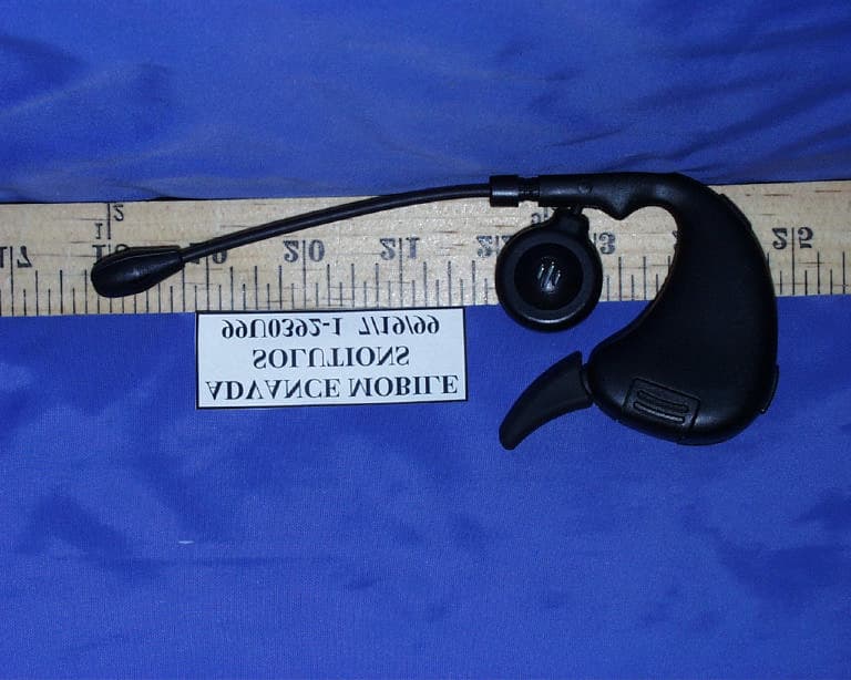
Click to zoom
Application Details
- Equipment Class
- DCD - Part 15 Low Power Transmitter Below 1705 kHz
- Date of Grant
- Nov 14, 1999
- Application Purpose
- Original Equipment
- Date of Application
- Aug 03, 1999
- Equipment Note
- WIRELESS HEADSET TRANSMITTER
- Frequency Range
- 0.48400000 - 0.48400000
- Country
- United States
Documents & Files
Document Text
Text extracted from the exhibit documents filed with the FCC. Open a document above to read the original.
Users Manual
ADVANCED MOBILE SOLUTIONS, INC AIR MAGIC WIRELESS HEADSET & BASE STATION USER’S GUIDE HOW TO USE THE HEADSET AND BASE STATION STEP 1 Plug base station into cigarette lighter outlet. SETP 2 Plug the right angle 2.5mm plug from the base station into the audio receptacle or adapter on the phone. STEP 3 Adjust microphone tip to point to the corner of your mouth and adjust the earhook for proper stability. SETP 4 Turn on the headset by pushing the ON button. During a call, should it be necessary to adjust the receiver volume, push the three step volume button to achieve the correct level. BASE STATION OPERATION • Make sure the second battery pack is in the base station charging receptacle. • The LED on the right side of the base station will display the charging status of the battery, Red is fast charge and Green fully charged. • If the battery power drops below sufficient power level, you will notice a slight increase in background noise. Remove battery pack from the headset and replace it with a freshly charged battery pack from the base station. Place the discharged battery pack from the headset into the base station charger. • The newly charged battery will have a 4 hour on time • Normal charging time for the battery is 2.5 hours. HEADSET OPERATION • During a call, should it be necessary to adjust the receiver volume, push the three step volume button to achieve the correct level. • Transmit and receive range is 5 feet from the base station. If you exceed this range, the headset will generate an out of range tone every four seconds, up to eight times for a total of 32 seconds. When you return back into range the headset will still be linked to the base station. If you stay out of range for more than 32 seconds, the headset will automatically turn off to conserve battery power. At that time the yellow LED will be off, indicating a broken link. • To establish the link, simply turn the headset back on and the yellow LED will be back on showing the link has been established. • If for some reason you experience some interference with other electronic devices such as labtop computer TV set or radio etc. you can change the frequency setting by removing the battery pack from the headset and changing the 2 channel select switch to the other position. CAUTION: • Do not attempt to put on your headset or change the battery while driving. • Only turn off the headset when you leave the car or when you do not wish to use your cellular phone. FCC COMPLIANCE STATEMENT: This device complies with part 15 of the FCC Rules. Operation is subject to the following two conditions: (1) This device may not cause harmful interference, and (2) this device must accept any interference received, including interference that may cause undesired operation. CAUTION: Changes or modifications not expressly approved by the manufacturer responsible for compliance could void the user’s authority to operate the equipment
Block Diagram
HEAD SET BLOCK DIAGRAM VDD_SWITCH VDD (3.0V) AM1010 Wednesday, July 28, 1999 11 {Model Code} {Document Number} B Short Range Wireless Head Set AMH1010BLK-X0.DSN X0 Kevin Park JULY,28,1999 {Name} {Name} {Date} {Date} {Date} {Name} Head set block diagram Advanced Mobile Solutions Inc. 375 Rheem Blvd, Moraga, CA 94556Tel:1-925-377-3200 Web:www.advancedmobile.com Model Code & Name Doc. No: Size: Sheetof CONFIDENTIAL AND PRO- PRIETARY INFORMATION This material is for use only by the recipient thereof directly from Advanced Mobile Solutions, Inc. This is the property of Advanced Mobile Solutions, Inc. and shall not be made available or disclosed without the proper written authorization thereof. Date: Drawn by Checked by Checked by Approved by E.C.O. Rev.ECO No Fax:1-925-377-3400 Title File Name: Date Rev. RX Antenna AGC AMP MIXER Y1 3.58MHz 455K FILT CF1 TX Antenna C29 AMP BUFFER AGC R30 OOR ADJ C51 S3 VOLUME S1 SW SPST S2 CHANNEL SW MICROPHONE SPEAKER U5 -1U5 -6 + C41 AUDIO OUT R6,8,12 C3,10,14 C6,13,17 I-Q MODULATOR AMP & MIXER RF AGC Q2,C37 U4,R36 R39,C42 TX PLL LO1 PLL LO2 PLL EXCEPT THE COMPONANT WHICH HAS REFERENCE NUMBER LO1 RF LOAD L4,C39,40 R31 L3,CT32,R27 L2,C11,7,R10 C15,57,58,59 Transmit Driver . AUDIO COMPRESSOR LOOP FILTERS . AM Modulation GAIN CONTROL LO2 LO2 XMIT INTERNAL BLOCK OF HEAD SET ASIC(AH1002) LO1 EXPANDER . PLL SYNTHESIZER MIC AMP MIC BIAS & AMP U3,R15,24 R26,C38 HIGH PASS FILTER R17,20 C22,24 LO1 IQ AMPIFIER U7,R42,43 C52,53,R41 LOOP FILTER R36,C49 C46,Q3,4 R1,2,3,4,5 RF AMP Q1,R21,22,29 C30,31,R23 POWER CONTROL POWER SWITCH U5,U6 VDD_SWITCH VDD_SWITCH VDD_SWITCH VDD_SWITCH TONE GENERATOR OOR TONE SW U10,D1,3 R49,33 C44,60 U9,L1,C1,C2 DRIVER * WIDE LINE MEANS BUS LINE REGULATOR DC 3.0V U8,C56,55 R44 ,45 D2,C54 BATTERY 3.6V/40mAH
ID Label/Location Info
PROPOSED FCC ID LABEL FORMAT AND LOCATION APPLICANT:ADVANCED MOBIL SOLUTIONS, INC. MODEL NO: AM1010H FCC ID: NQ2AM1010H FCC ID:NQ2AM1010H FCC ID LABEL AREA
Operational Description
Theory of Operation AM1010B and AM1010H Prepared by Kevin Park Version 1.1 1.0 Theory of Operation 1.1 System Abstract: The characterstics of AM1010 is that One Chip IC offers all functions. AURA IC’s Short Range Magnetic Induction ASIC, AB1002 and AH1002 provide audio signal and RF signal for BU(AM1010B Base Unit) and HU(AM1010H Headset Unit). AM1010 IC sends the signal using the method of PWM (Puls Width Modulation) and receives AM modulation signal through LC antenna. Wireless communication’s receiver and transmitter are created by Magnetic Induction and the power consumption is very low and the unwanted emission are minimized. Receiver signal is controlled by AGC(Automatic Gain Controller) and it creates audio signal by IQ-Modulator and Direct Conversion method. Audio signal transmits low noise signal though Compressor and Expender in the IC. ASIC has TX, LO1, LO2 derived by PLL and can choose maximum 2 channels. 1.2 Dimensional Antenna The biggest characteristic of AM1010 is that 3 receiver and transmitter antenna with X,Y,Z axis are built in BU. This method prevents from lowering signal output by the signal direction of Magnetic Induction. Each axis of receiver antenna and transmitter antenna are constructed in the same direction. ASIC of BU do summing the signals from each axis and combines communication signals and then sends the signal by transmitter antenna which finds the strongest signals among the 3 axis antenna. The selection of transmitter antenna continues during communication and BU’s transmitter antenna is selected automatically which is depends on the direction of HU’s transmitter antenna. 1.3 X-Tal, TX, Local Oscillator 1 and 2 The set up for AM1010 wireless frequency is determined by Channel Switch. The channel can have maximum 8. Transmitter frequency is controlled by the internal PLL, according to selected channel value and transmitter frequency is calculated according to the following table. Reference frequency is obtained from X-tal(3.58MHz). TX Oscillator and Fist Local Oscillator and Second Local Oscillator are created internal ASIC. Especially, HU’s wireless frequency can be automatically tracking according to Base’s transmitter frequency. HU’s wireless frequency Tracking can control automatically HU’s Reference frequency by Varactor Diode which is installed inside of HU’s ASIC AH1002. Therefore, for frequency variation due to the environment, HU and BU can maintain the same frequency. 1.4 Modulation After BU and HU pass Compressor equally, communication signals change the internal PWM. The changed signals become Buffering through Inverter IC which connects to external ASIC and AM signals are Radiated through LC antenna. 1.5 AGC(Automatic Gain Control) The signal received by antenna is amplified by input amplifier in internal ASIC. Because the amplifier gain is fixed by RF-load, when the over limit signal sends to antenna, the signal becomes saturated and it causes signal Distortion. To prevent this, AGC (Atomatic Gain Controller) using Transistor Switch is built between antenna and RF-Load. When the internal Gain Controller voltage becomes over the limit level, it will turn on Transistor Switch and reduce the impedance of Rf-load and lower the Gain 1.6 Demodulator After the receiver signal mixes with LO1(First Local Oscillator) inside ASIC and passes 455KHz IF filter outside, it makes communication signal though I-Q modulator. In I-Q modulator, it mixes with LO2 (second Local Oscillator). In BU, separate I-Q modulator is installed where 2 I-Q Modulator will inspect the third axis receiver signal and will transmit to the direction of the antenna which finds the strongest signal. 1.7 OOR (Out of Range Detector) Depending on the demodulated communication signal volume, it sets OOR by comparing the DC size for found Gain Error and externally fixed OOR Range with resistance. BU indicates the status of OOR in Yellow color LED and HU warns the distance Tone signal to the user through speaker. When OOR is set, it mutes the block of internal receiver communication output and prevents the noise signal to go outside through Audio Line. Table 1: Headset Transceiver Frequency Chart <FS2, FS1, FS0>SynthFreq (Hz)MN <1,0,0>TX LO1 LO2 RX 484238 2260992 455111 1805880 133 69 125 9 1 9 <1,0,1>TX LO1 LO2 RX 494796 2277376 455475 1821900 151 139 139 10 2 10 Table 2: Base Unit Transceiver Frequency Chart <FS2,FS1,FS0>SynthFreq (Hz)MN <1,0,0>TX LO1 LO2 RX 1805880 939349 455111 484238 496 86 125 9 3 9 <1,0,1>TX LO1 LO2 RX 1821900 950272 455475 494796 278 29 139 5 1 10
Operational Description
Theory of Operation AM1010B and AM1010H Prepared by Kevin Park Version 1.2 1.0 Theory of Operation 1.1 System Abstract: The characterstics of AM1010 is that One Chip IC offers all functions. AURA IC’s Short Range Magnetic Induction ASIC, AB1002 and AH1002 provide communications signal for BU(AM1010B Base Unit) and HU(AM1010H Headset Unit). AM1010 IC sends and receives AM modulation signal through LC antenna. Wireless communication’s receiver and transmitter are created by Magnetic Induction and the power consumption is very low and the unwanted emission are minimized. Receiver signal is controlled by AGC(Automatic Gain Controller) and it creates communication signal by IQ-Modulator and Direct Conversion method. Communication signal transmits low noise signal though Compressor and Expender in the IC. ASIC has TX, LO1, LO2 derived by PLL and can choose maximum 2 channels. 1.2 Dimensional Antenna The biggest characteristic of AM1010 is that 3 receiver and transmitter antenna with X,Y,Z axis are built in BU. This method prevents from lowering signal output by the signal direction of Magnetic Induction. Each axis of receiver antenna and transmitter antenna are constructed in the same direction. ASIC of BU do summing the signals from each axis and combines communication signals and then sends the signal by transmitter antenna which finds the strongest signals among the 3 axis antenna. The selection of transmitter antenna continues during communication and BU’s transmitter antenna is selected automatically which is depends on the direction of HU’s transmitter antenna. 1.3 X-Tal, TX, Local Oscillator 1 and 2 The set up for AM1010 wireless frequency is determined by Channel Switch. The channel can have maximum 2. Transmitter frequency is controlled by the internal PLL, according to selected channel value and transmitter frequency is calculated according to the following table. Reference frequency is obtained from X-tal(3.58MHz). TX Oscillator and Fist Local Oscillator and Second Local Oscillator are created internal ASIC. Especially, HU’s wireless frequency can be automatically tracking according to Base’s transmitter frequency. HU’s wireless frequency Tracking can control automatically HU’s Reference frequency by Varactor Diode which is installed inside of HU’s ASIC AH1002. Therefore, for frequency variation due to the environment, HU and BU can maintain the same frequency. 1.4 Modulation After BU and HU pass Compressor equally, communication signals change and become Buffering through Inverter IC which connects to external ASIC and AM signals are Radiated through LC antenna. 1.5 AGC(Automatic Gain Control) The signal received by antenna is amplified by input amplifier in internal ASIC. Because the amplifier gain is fixed by RF-load, when the over limit signal sends to antenna, the signal becomes saturated and it causes signal Distortion. To prevent this, AGC (Atomatic Gain Controller) using Transistor Switch is built between antenna and RF-Load. When the internal Gain Controller voltage becomes over the limit level, it will turn on Transistor Switch and reduce the impedance of Rf-load and lower the Gain 1.6 Demodulator After the receiver signal mixes with LO1(First Local Oscillator) inside ASIC and passes 455KHz IF filter outside, it makes communication signal though I-Q modulator. In I-Q modulator, it mixes with LO2 (second Local Oscillator). In BU, separate I-Q modulator is installed where 2 I-Q Modulator will inspect the third axis receiver signal and will transmit to the direction of the antenna which finds the strongest signal. 1.7 OOR (Out of Range Detector) Depending on the demodulated communication signal volume, it sets OOR by comparing the DC size for found Gain Error and externally fixed OOR Range with resistance. BU indicates the status of OOR in Yellow color LED and HU warns the distance Tone signal to the user through speaker. When OOR is set, it mutes the block of internal receiver communication output and prevents the noise signal to go outside through Audio Line. Table 1: Headset Transceiver Frequency Chart <FS2, FS1, FS0>SynthFreq (Hz)MN <1,0,0>TX LO1 LO2 RX 484238 2260992 455111 1805880 133 69 125 9 1 9 <1,0,1>TX LO1 LO2 RX 494796 2277376 455475 1821900 151 139 139 10 2 10 Table 2: Base Unit Transceiver Frequency Chart <FS2,FS1,FS0>SynthFreq (Hz)MN <1,0,0>TX LO1 LO2 RX 1805880 939349 455111 484238 496 86 125 9 3 9 <1,0,1>TX LO1 LO2 RX 1821900 950272 455475 494796 278 29 139 5 1 10
Schematics
THIS DRAWING CONTAINS PROPRIETARY INFORMATION OF AURA COMMUNICATIONS, INC. EXCEPT AS AUTHORIZED BY AURA IN A SEPARATE WRITING, THIS DOCUMENT, IN WHOLE OR IN PART, SHALL NOT BE COPIED, USED, OR DISCLOSED TO OTHERS, AND SHALL BE RETURNED TO AURA UPON REQUEST. THIS NOTICE MAY NOT BE REMOVED. AM1010HX3.1 Short Range Wireless Head set ADVANCED MOBILE SOLUTIONS.,INC. 375 Rheem Blvd. Moraga CA 94556 Tel : 925-377-3200 Fax : 925-377-3400 Web : www.advancedmobile.com C 11Tuesday, June 29, 1999 Title SizeDocument NumberRev Date:Sheet of VDD VDD VDD VDD VDD VDD VDD VDD VDD VDDVDD VDD VDD_SW VDD_SW VDD_SW VDD VDD_SW VDD_SW VDD VDD REM_SW1 REM_SW1 Y1 32,768 HZ R7 220K R1 1M C17 471 R12 220K C14 682 R8 150K C13 221 C10 182 R6 68K C6 221 C3 822 + C41 22uF/6.3V R25 2.2K R44 107K C51 104 C29 104 R36 82K R32 SHORT R41 150K C11 222 R3 2M R42 18K R43 22K C37 221R28 100K C7 561 C15 121 S1 ON/OFF S3 VOL L2 36UH E1 BATT + 1 R5 510K R9 10M Q2 MMBT4403L Q3 MMBT4403L Q4 MMBT4403L C30 472 C31 681 R23 1K CF1 455D 1 2 3 R34 2.2K R35 56K D3 BAS21ZXCT 13 R49 1M + C44 2.2uF/6.3V R39 2M R38 270K R33 390K D1 BAS21ZXCT 1 3 C8 153 R31 3.9KC40 56p C28 104 C23 103 C48 103 C35 153 E2 BATT - 1 R4 2M U8 MIC5205BM5 1 4 5 2 3 IN ADJ OUT GND EN +C46 0.22uF/35V +C49 2.2uF/6.3V R18 39K C45 391 C34 181 C52 271 U5 NC7S04 24 5 3 C54 104 R21 100K C9 153 C20 103 + C55 22uF/6.3V U6 NC7S04 24 5 3 R14 100K + C60 1uF/10V C50 103 CT32 50p + C47 22uF/6.3V R27 33K C43 102 Q1 MMBT4403L R30 240K + C42 4.7uF/6.3V C39 271 R29 100K U10 NC7S04 24 5 3 R22 12K + C25 1uF/10V C53 223 L4 22UH + - U4 LMV321 1 3 4 2 5 C12 103 C36 153 C16 104 C4 5p D2 BAS21ZXCT 1 3 + - U7 LMV321 1 3 4 2 5 L3 36UH U2 AH1002 1 2 3 4 5 6 7 8 9 10 11 12 131415161718192021222324 25 26 27 28 29 30 31 32 33 34 35 36 373839404142434445464748 D_VDD D_GND TX_LF LO1_LF LO2_LF OOR IM VM VREF_RX RX RFLOAD CF_I CF_OOOR_ADJAGCIQVDD_LNALOBATT_ADJS_VSSCHRG_PUMPSYS_STATUSCHRG_CURRENTSPKR_OUT EXPDR_IN EXPNDR_TIME CMPRS_TIME CMPRS_AUDIO CMPRS_OUT DC_FB MIC_IN MUTE VOL ON_OFF REM_SW1 REM_SW2 TX AUDIO_N AUDIO_P A_VDD A_GND S_VDD FS0FS1FS2 XTAL_IN XTAL_OUT VARAC C56 471 R45 150K R11 100K C5 33p S2 FREQ SEL JP1 JumperC57 33p JP3 Jumper C58 68p C59 151 JP2 Jumper R16 270K MIC EM-118 C61 33p R15 8.2K R26 6.8K C27 33p C24 472 C18 104 + - U3 LMV321 1 3 4 2 5 C22 102 C26 471 + C21 22uF/6.3V + C19 22uF/6.3V R17 47K R13 100 R24 270K R20 120K C38 224 R10 2R7 L1 22UH + C1 22uF/6.3V C2 103 R2 2M P2A SPK+ 1 P2B SPK- 1 SPK SPEAKER W1 GRN 1 W2 BLK 1 W3A RED 1 W3B BLK 1 P3B MIC- 1 P3A MIC+ 1 TP1 AGC TP2 Q U9F 74AC04 1312 14 7 U9B 74AC04 34 14 7 U9C 74AC04 56 14 7 U9E 74AC04 1110 14 7 U9D 74AC04 98 14 7 U9A 74AC04 12 7 14 + - U11A LM393 1 2 3 C61 333 R51 33K R50 1M R52 270K TRANSMIT CHANNEL E: 484.238 KHz F: 494.796 KHz RECEIVE CHANNEL E: 1.8059 MHz F: 1.8219 MHz THESE SELECTS ARE EITHER SHORTED OR OPEN. 3.0VDC F F E E
Test Report
ELECTROMAGNETIC EMISSIONS COMPLIANCE REPORT CERTIFICATION TO FCC PART 15 REQUIREMENTS for INTENTIONAL RADIATOR 484, 494KHz TRANSMITTER MODEL NO: AM1010H FCC ID :NQ2AM1010H REPORT NO: 99U0392 ISSUE DATE: AUGUST 02, 1999 Prepared for ADVANCED MOBIL SOLUTIONS, INC. 375 RHEEM BLVD. MORAGA, CA 94556 Prepared by COMPLIANCE ENGINEERING SERVICES, INC. d.b.a. COMPLIANCE CERTIFICATION SERVICES 1366 BORDEAUX DRIVE SUNNYVALE, CA 94089, USA TEL: (408) 752-8166 FAX: (408) 752-8168 REPORT NO:99T0392 FCC ID:NQ2AM1010H DATE:JULY 06, 1999 COMPLIANCE ENGINEERING SERVICES, INC.CCS DOCUMENT NO:CCSUP4020B 1366 BORDEAUX DRIVE, SUNNYVALE, CA 94089, USATEL:(408)752-8166 FAX:(408)752-8168 This report shall not be reproduced except in full, without the written approval of CCS. TABLE OF CONTENTS PAGE 1. VERIFICATION OF COMPLIANCE..................................1 2. Product Description.........................................2 3. Test Facility...............................................2 4. Measurement Standards.......................................2 5. Test Methodology............................................2 6. Measurement Equipment Used..................................2 7. RADIATED EMISSION LIMITS....................................3 8. SYSTEM TEST CONFIGURATION...................................3 9. Test Procedure..............................................4 10. SETUP PHOTO................................................5 11. TEST RESULT................................................6 TEST DATA REPORT NO:99u0392 FCC ID:NQ2AM1010H DATE:07/06/99 PAGE NO: 1 COMPLIANCE ENGINEERING SERVICES, INC.CCS DOCUMENT NO:CCSUP4020B 1366 BORDEAUX DRIVE, SUNNYVALE, CA 94089, USATEL:(408)752-8166 FAX:(408)752-8168 This report shall not be reproduced except in full, without the written approval of CCS. 1. VERIFICATION OF COMPLIANCE COMPANY NAME : ADVANCED MOBIL SOLUTIONS, INC. 375 RHEEM BLVD. MORAGA, CA 94556 CONTACT PERSON: SANDRA SOHN/ REGULATORY TEST ENGINEER TELEPHONE NO.: (925)377-3257 EUT DESCRIPTION: 484, 494KHz TRANSMITTER MODEL NAME/NUMBER: AM1010H FCC ID: NQ2AM1010H DATE TESTED : JULY 6,1999 REPORT NUMBER: 99U0392 TYPE OF EQUIPMENTWIRELESS HEADSET TO BE USED INSIDE A VEHICLE FOR CELL PHONE EQUIPMENT TYPE484, 494KHZ TRANSMITTER MEASUREMENT PROCEDUREANSI C63.4 / 1992 LIMIT TYPECERTIFICATION FCC RULECFR 47, PART 15 The above equipment was tested by Compliance Engineering Services, Inc. for compliance with the requirements set forth in CFR 47, PART 15. This said equipment in the configuration described in this report shows that maximum emission levels emanating from equipment are within the compliance requirements. MIKE C.I. KUO / VICE PRESIDENT COMPLIANCE ENGINEERING SERVICES, INC. REPORT NO:99u0392 FCC ID:NQ2AM1010H DATE:07/06/99 PAGE NO: 2 COMPLIANCE ENGINEERING SERVICES, INC.CCS DOCUMENT NO:CCSUP4020B 1366 BORDEAUX DRIVE, SUNNYVALE, CA 94089, USATEL:(408)752-8166 FAX:(408)752-8168 This report shall not be reproduced except in full, without the written approval of CCS. 2. Product Description Fundamental Frequency 484, 494KHz Power Source 3.6VDC BATTERY Usage Audio Power Requirement 3.6V DC Antenna Requirement Permanently attached Associated Transceiver FCC ID:NQ2AM1010B 3. Test Facility The 3/10/30 meter open area test site and conducted measurement facility used to collect the radiated data is located at 561F Monterey Road, Morgan Hill, California, U.S.A. A detailed description of the test facility was submitted to the Commission on May 27,1994. 4. Measurement Standards The site is constructed and calibrated in conformance with the requirements of ANSI C63.4/1992. 5. Test Methodology For an intentional radiator, the spectrum shall be investigated from the lowest radio frequency signal generated in the device, without going below 9 KHz, up to at least the tenth harmonic of the highest fundamental frequency or to 40 GHz, whichever is lower. (CFR 47 Section 15.33) 6. Measurement Equipment Used ManufacturerModel Number DescriptionCal Due Date H.P.8566BSpectrum Analyzer (100Hz – 22GHz) 09/1999 EMCO6502Active Loop Antenna (.009-30.0MHZ) 2/2000 H.P.8447DPreamplifier09/1999 REPORT NO:99u0392 FCC ID:NQ2AM1010H DATE:07/06/99 PAGE NO: 3 COMPLIANCE ENGINEERING SERVICES, INC.CCS DOCUMENT NO:CCSUP4020B 1366 BORDEAUX DRIVE, SUNNYVALE, CA 94089, USATEL:(408)752-8166 FAX:(408)752-8168 This report shall not be reproduced except in full, without the written approval of CCS. (0.1 - 1300 MHz) 7. RADIATED EMISSION LIMITS GENERAL REQUIREMENTS SECTION 15.209. 8. SYSTEM TEST CONFIGURATION Support Equipment: DC Power Supply, Kenwood, PA36-3A Cellular Phone, Motorola Star Tac, 80067NABPA, FCC ID:IHDT5VG1 EE3 Base Station, Advanced Mobil Solutions, AH1010B Radiated Open Site Test Set-up HeadsetBase-station 12VDC Power Supply Cellular Phone REPORT NO:99u0392 FCC ID:NQ2AM1010H DATE:07/06/99 PAGE NO: 4 COMPLIANCE ENGINEERING SERVICES, INC.CCS DOCUMENT NO:CCSUP4020B 1366 BORDEAUX DRIVE, SUNNYVALE, CA 94089, USATEL:(408)752-8166 FAX:(408)752-8168 This report shall not be reproduced except in full, without the written approval of CCS. 9. Test Procedure Radiated Emissions, 15.209 Test Set-up for frequency range 0.4-20MHz Antenna mast Ground plane 1 - 4 meters 3 meters Antenna turntable preamplifier/spectrum analyzer Fig. 1 1. The EUT was placed on a wooden table on the outdoor ground plane. The search antenna was placed 3-meters from the EUT. 2. The turntable was slowly rotated to locate the direction of maximum emission. The EUT was moved throughout the. 3. Once maximum direction was determined, the search antenna was raised and lowered .The maximum readings so obtained are recorded in the data listed below. 4. Steps 1-3 were repeated at 5 and 10 meters. 5. 3, 5 and 10 meter measurements were plotted on semi-log paper to extrapolate to 30 meter data. REPORT NO:99u0392 FCC ID:NQ2AM1010H DATE:07/06/99 PAGE NO: 5 COMPLIANCE ENGINEERING SERVICES, INC.CCS DOCUMENT NO:CCSUP4020B 1366 BORDEAUX DRIVE, SUNNYVALE, CA 94089, USATEL:(408)752-8166 FAX:(…
Text truncated - open the document above for the full version.
Test Report
Advanced Mobile Solutionshands free communication device for car cell phoneFCC ID: NQ2AM1010HFrequency Stability re: FCC Information RequestDate performed: 10/15/1999Tx Output (kHz) 494.75 Frequency (kHz) Temp Delta(Hz) Frequency (MHz) Voltage Delta (Hz) 0 -30 ######### No osc. 494.819 4.1 69.0 494.804 -20 54.0 494.828 3.6 78.0 494.801 -10 51.0 494.824 3.3 74.0 494.819 0 69.0 494.809 3.11 59.0 494.808 10 58.0 494.805 2.75 55.0 494.84 20 90.0 494.81 30 60.0 494.799 40 49.0 494.799 50 49.0 494.809 60 59.0
Contact Information
Applicant
Sandra Sohn(Regulatory Test Engineer)
925-377-3200Fax: 925-377-3400
Technical Contact
COMPLIANCE ENGINEERING SERVICES, INC.MIKE KUO
[email protected]408-752-8166
1366 BORDEAUX DRIVE · SUNNYVALE, California · United States
Non-Technical Contact
COMPLIANCE ENGINEERING SERVICES, INC.MIKE KUO
[email protected]408-752-8166
Test Firm
Compliance Certification Services IncSteve Cheng
Technical Specifications
| # | Rule Parts | Frequency Range | Power Output |
|---|---|---|---|
| 1 | 15C | 0.484 MHz - 0.484 MHz | - |
Other Applications from Advanced Mobile Solutions, Inc.
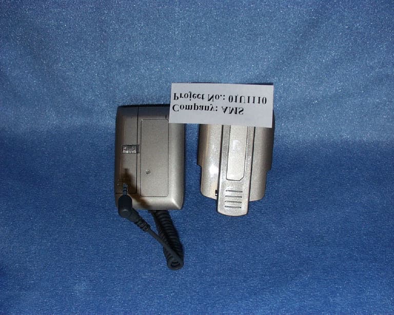
NQ2AM1032
Jun 23, 2002RF Wireless Belt Clip Base Station
Equipment Class
DXT - Part 15 Low Power Transceiver, Rx Verified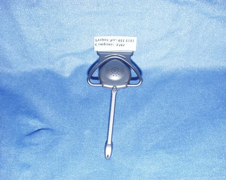
NQ2AM1062
Jun 23, 2002RF Wireless Hands-Free Headset
Equipment Class
DXT - Part 15 Low Power Transceiver, Rx Verified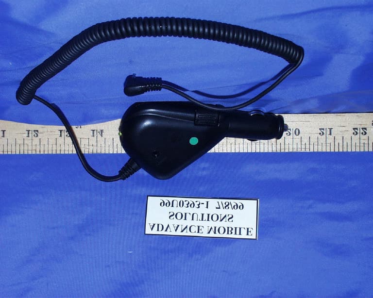
NQ2AM1010B
Sep 01, 1999WIRELESS BASE STATION TRANSCEIVER
Equipment Class
DXT - Part 15 Low Power Transceiver, Rx Verified