NQE1005Meter Reading Transmitter
World Wireless Communications Inc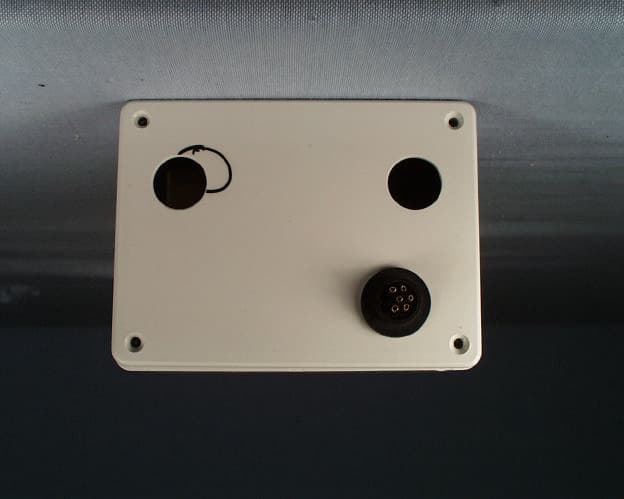
Click to zoom
Application Details
- Equipment Class
- DSS - Part 15 Spread Spectrum Transmitter
- Date of Grant
- Sep 14, 1998
- Application Purpose
- Original Equipment
- Date of Application
- Jul 05, 1998
- Equipment Note
- Meter Reading Transmitter
- Frequency Range
- 905.80000000 - 924.20000000
- Country
- United States
Documents & Files
Document Text
Text extracted from the exhibit documents filed with the FCC. Open a document above to read the original.
Users Manual
COMMUNICATION CERTIFICATION LABORATORYTEST REPORT: 73-6560 FCC ID: NQE1005 Exhibit 8: User’s Manual Installation Manual Declaration of Compliance The following declaration applies to World Wireless Communications Corp NQE1005 TIM spread spectrum transmitter. This device complies with part 15 of the FCC Rules. Operation is subject to the following two conditions: (1) This device may not cause harmful interference, and (2) this device must accept any interference received, including interference that may cause undesired operation. Caution to the user : Changes or modifications not expressly approved by World Wireless could void the authority to operate this equipment. The responsible party for this declaration is: World Wireless Communications Corp 150 Wright Brothers Drive / Suite 560 Salt Lake City, Utah 84116 Phone: (801) 575-6600 Installation Instructions The NQE1005 will be installed by professionals with special tools for removing and installing meter faces equipped with pickup sensors. The NEQ1005 is designed as a sealed unit with internal batteries and antennas, to insure the installed unit will comply with FCC rules, and will only be sold to OEMs and Utilities with trained staff. COMMUNICATION CERTIFICATION LABORATORYTEST REPORT: 73-6560 FCC ID: NQE1005 Note to Installers: Must not install this equipment in locations that could cause RF exposure to persons where the distance is lees than 20 centimeters. Hardware Requirements Antennas: Built in: no connection required Power Supply: The NQE1005 Transmitter is a sealed unit with internal lithium 3.6-volt batteries. Designed for 10-year service under normal conditions. No maintenance required. To insure battery freshness connection to internal circuitry is made by external jumper as shown in figure 2. 3V battery 6 5 4 3 2 1 Figure: 2 Contact in meter 900 MHz Transmitter Division Reg Debounce Time Preset Cnt NV Memory CPU Count accumulator COMMUNICATION CERTIFICATION LABORATORYTEST REPORT: 73-6560 FCC ID: NQE1005 Procedure The NEQ1005 TIM Transmitter must first be programmed from a computer using World Wireless provided software, and the programming harness, which connects the Tim to the parallel printer port. This software sets three parameters and causes them to be stored in nonvolatile memory A) Unit address. B) Contact debounce time C) Preset count. The installation of the NQE1005 TIM Transmitter requires a plug connection to an appropriate gas meter (or other appliance with a dry switch contact), that closes for each metered event. This connector provides power to the unit by connecting pin 1&2 through the wiring harness. The same connector and harness provides interface to the meter contacts. This completes the setup and installation of the NEQ1005 TIM Transmitter.
Users Manual
COMMUNICATION CERTIFICATION LABORATORYTEST REPORT: 73-6560 FCC ID: NQE1005 Exhibit 8: User’s Manual NQE1005 TIM TRANSMITTER © 1998 World Wireless Communications Corp. Table of Contents FCC Compliance .............................................................. 1 Hardware Requirements............................................. 2 Antennas Power Supply Receiver Functional Description. ........................................................4 Specifications....................................................................7 FCC Label .....................................................................11 Appendix .............................................................A Schematics PCB Layout Installation Manual Declaration of Compliance The following declaration applies to World Wireless Communications Corp NQE1005 TIM spread spectrum transmitter. This device complies with part 15 of the FCC Rules. Operation is subject to the following two conditions: (1) This device may not cause harmful interference, and (2) This device must accept any interference received, including interference that may cause undesired operation. 2. Caution Changes or modifications not expressly approved by World Wireless could void the authority to operate this equipment. The responsible party for this declaration is: World Wireless Communications Corp 150 Wright Brothers Drive / Suite 560 Salt Lake City, Utah 84116 Phone: (801) 575-6600 COMMUNICATION CERTIFICATION LABORATORYTEST REPORT: 73-6560 FCC ID: NQE1005 Note to Installers Do not install this equipment in locations that could cause RF exposure to persons where the distance is less than 20 centimeters. Hardware Requirements Antennas Built in: No connections required Power Supply The NQE1005 Transmitter is a sealed unit with internal lithium 3.6 volt battery designed for 10 year service under normal conditions. No maintenance required. COMMUNICATION CERTIFICATION LABORATORYTEST REPORT: 73-6560 FCC ID: NQE1005 NQE1005 TIM TRANSMITTER Functional Description General Description The TIM Transmitter remains in "sleep" mode until an input event occurs. The TIM Transmitter wakes up to monitor and accumulates switch closures. Events represent units of power or other similar items measured. Events are monitored by closures between pins 1 and 6 of connector JP2. Events are accumulated and compared to a preset number (1 to 10,000 set at installation).When this count is reached it will trigger, transmitting a data packet containing the total accumulated count. This data is transmitted to a receiver station using FSK (Frequency Shift Keying) modulation, on 1 of 25 different frequency channels ranging from 902 to 928 MHz. The complete packet transmits within 0.043 seconds. After the data has transmitted, the transmitter returns to “sleep” mode and collects another set of data. This process is then repeated when the next preset count is reached and transmitted on the next frequency from the hop table. As an example, let’s say the meter count is at 1000 units of gas used and the preprogrammed event count is set at 10. The TIM wakes up 10 times to advance the accumulator but will only advance the transmitter channel on the tenth event. At this point the accumulated count of 1010 would be sent. All 25 transmit frequency channels are used before any given frequency is repeated. The worst case or shortest delay that the firmware allows is 0.043 seconds between channels. Accounting for switch debounce of 1ms, a wakeup time of 1ms, 4ms to setup the PLL, and 0.037 seconds to transmit. It takes 1.075 seconds to visit all 25 channels (0.043x25=1.075 seconds). Any one channel could be visited 9.3 times in 10 seconds (10\1.075 = 9.30). Total transmit time for any 10 second period is 9.3x .037 for 0.344 seconds, 0.4 seconds is COMMUNICATION CERTIFICATION LABORATORYTEST REPORT: 73-6560 FCC ID: NQE1005 allowed. is contact closed sleep No Yes 1ms wakeup 1 to 255ms debounce Inc event count is event count equal to preset count No Yes advance TX channel Transmit accumulator count 37ms setup PLL 4ms Detailed Description The 4 MHz crystal (Y1) will provide a reference clock for the synthesizer IC (U2) and the micro- controller (U1). U1 will program the dividers in U2 to values that will select the appropriate frequency. The output of U2 (pin 4) will be filtered (C14, R11, C15, R24, C35, C46, R33, C47, R32, and C46) and will provide the tune voltage for the Voltage Controlled Oscillator (VCO). The VCO consists of D1, D2, Q1, Q3 and their associated resistors, capacitors, and inductors. The output of the VCO (Q3) will provide the feedback (via C19 and R20) for U2 (pin 8) and will also feed the Power Amplifier. The Power Amplifier consists of a low pass filter (C49, L8, C50, L9, and C51), Q2, Q5 and their associated resistors, capacitors, and inductors. The output of the Power Amplifier (Q5) is then filtered by C33, C56, L10, C55, C24, C25, C62, C26, and C37. The output of C37 will then feed the antenna (the antenna is etched on the PCB). Serial data from U1-2 passes through a variable resistor (R2) and is low pass filtered by C41, R28, C42, R29, and C43. This signal then modulates the VCO using D1, C38, and C36. R2 sets the frequency deviation of the output frequency. When in “sleep” mode, U1 (pins 3 & 6) powers down the VCO and power amplifier by setting the base voltage on Q4 and Q6 to a high voltage (3.6 volts). Prior to transmitting, U1 pulls these two signals to a low (0 volts), which will apply power to the VCO and power amplifier. JP1 is used as an interface to do “on-board” programming of the micro- controller (U1). JP2-2 & 3 allows the battery (3.6 Volts) to be disconnected until the unit is installed out in the field. J2-4, 5, & 6 will provide an external interface to U1. COMMUNICATION CERTIFICATION LABORATORYTEST REPORT: 73-6560 FCC ID: NQE1005 Micro- controller Synthesizer IC 4.0 MHz Clock VCO Power Amp Filter Filter Antenna TITANIC TIM TRANSMITTER Block Diagram Input Data Modula…
Text truncated - open the document above for the full version.
Cover Letter(s)
COMMUNICATION CERTIFICATION LABORATORYTEST REPORT: 73-6560 FCC ID: NQE1005 Exhibit 13: Cover Letters July 7, 1998 FEDERAL COMMUNICATIONS COMMISSION Equipment Authorization Division 7435 Oakland Mills Road Columbia, MD 21046 To Whom It May Concern: Enclosed is a FCC Part 15, Subpart C, Section 15.247 Certification application for the World Wireless Communications, Inc. Model NQE1005, FCC ID: NQE1005. Please let me know if I can be of further assistance. Sincerely yours, COMMUNICATION CERTIFICATION LABORATORY Joseph W. Jackson V.P. Marketing
Cover Letter(s)
1 - 1 -1 ENGINEERING GROUP July 7, 1998 FEDERAL COMMUICATIONS COMMISSION Attention: Greg Czumak 7435 Oakland Mills Road Columbia, MD 21046 SUBJECT: Request for Confidentiality FCC ID: NQE 1005 Dear Greg: In accordance with § 0.459 of CFR 47, World Wireless Communication request confidentiality for the following items: 1. Technical Description 2. Block Diagram and Schematic Diagrams These items contain detailed system and equipment description and related information about the product which World Wireless Communication considers to be proprietary, confidential and a custom design which otherwise would not be released to the general public. Since this design is a basis from which future technological products will evolve, World Wireless Communication also feels that this information would be of benefit to its competitors, and that the disclosure of the information is these exhibits would give our competitors an unfair advantage in the market. Best regard, ____________________ Stuart Biddulph Vice President - Engineering
External Photos
COMMUNICATION CERTIFICATION LABORATORYTEST REPORT: 73-6560 FCC ID: NQE1005 Exhibit 3: Photographs of Overall Appearance Front View of the NQE1005 COMMUNICATION CERTIFICATION LABORATORYTEST REPORT: 73-6560 FCC ID: NQE1005 Back View of the NQE1005
ID Label/Location Info
COMMUNICATION CERTIFICATION LABORATORYTEST REPORT: 73-6560 FCC ID: NQE1005 Exhibit 1: FCC ID Label Equipment Identification Label In accordance with the requirements of Sections 15.19 (a), 2.925 and 2.926 of the FCC Rules, the following information will be permanently affixed to the World Wireless Communications, Inc. Model NQE1005 spread spectrum transmitter as shown is the label placement sketch below: Place the label here Connector FCC ID: NQE1005 This device complies with Part 15 of the FCC rules. Operation is subject to the following two conditions: (1) This device may not cause harmful interference, and COMMUNICATION CERTIFICATION LABORATORYTEST REPORT: 73-6560 FCC ID: NQE1005 Photograph of the back exterior view
Internal Photos
COMMUNICATION CERTIFICATION LABORATORYTEST REPORT: 73-6560 FCC ID: NQE1005 Exhibit 9: Internal Photographs Component Side of the NQE1005 (with RF covers installed) COMMUNICATION CERTIFICATION LABORATORYTEST REPORT: 73-6560 FCC ID: NQE1005 Component Side of the NQE1005 (with RF covers removed) COMMUNICATION CERTIFICATION LABORATORYTEST REPORT: 73-6560 FCC ID: NQE1005 Solder Side of NQE1005
RF Exposure Info
COMMUNICATION CERTIFICATION LABORATORYTEST REPORT: 73-6560 FCC ID: NQE1005 Exhibit 11: RF Exposure/Environmental Evaluation The NQE1005 is professionally installed inside of a gas or electric meter and will always be greater than 20 centimeters from the user or nearby persons. Therefore testing for RF exposure was not required. Enclosed below is page 2 from the installation manual instructing the installer to ensure that this 20 centimeter distance is maintained. Note to Installers: Must not install this equipment in locations that could cause RF exposure to persons where the distance is lees than 20 centimeters. Hardware Requirements Antennas: Built in: No connections required Power Supply: The NQE1005 Transmitter is a sealed unit with internal lithium 3.6 volt battery designed for 10 year service under normal conditions. No maintenance required. Receiver and System Description: The NQE1005 is the companion to the NQE1002 Receiver from World Wireless Communications. This receiver fast scans all twenty five channels listed in the hopping table. If, valid data is detected from one of the Transmitters it stays on that channel long enough to accept an entire packet of data. The on board processor then passes the data out to a data collection system and continues to scan for the next transmitter. After each transmission the transmitters advances to the next frequency in the hopping table. When the input count is reached a new packet is sent. This completes the cycle. See one typical implementation below.
Test Report
COMMUNICATION CERTIFICATION LABORATORYTEST REPORT: 73-6560 FCC ID: NQE1005 Exhibit 6: Test Report TEST REPORT FROM: COMMUNICATION CERTIFICATION LABORATORY 1940 W. Alexander Street Salt Lake City, Utah 84119-2039 Type of Report: Certification TEST OF: NQE1005 FCC ID: NQE1005 To FCC PART 15.247, Subpart C Test Report Serial No: 73-6560 Applicant: World Wireless Communications Inc. 150 Wright Brothers Drive, Suite 560 Salt Lake City, UT 84116 Date(s) of Test: March 17, 1998 Issue Date: July 7, 1998 Equipment Receipt Date: March 17, 1998 COMMUNICATION CERTIFICATION LABORATORYTEST REPORT: 73-6560 FCC ID: NQE1005 CERTIFICATION OF ENGINEERING REPORT This report has been prepared by Communication Certification Laboratory to determine compliance of the device described below with the requirements of FCC PART 15.247, Subpart C. This report may be reproduced in full, partial reproduction may only be made with the written consent of the laboratory. The results in this report apply only to the sample tested. -Applicant:World Wireless Communications Inc. -Manufacturer:World Wireless Communications Inc. -Brand Name:TIM -Model Number:NQE1005 -FCC ID:NQE1005 On this 7 th day of July 1998, I, individually, and for Communication Certification Laboratory, certify that the statements made in this engineering report are true, complete, and correct to the best of my knowledge, and are made in good faith. COMMUNICATION CERTIFICATION LABORATORY Checked by: William S. Hurst, P.E. Vice President Tested by: Roger J. Midgley EMC Manager COMMUNICATION CERTIFICATION LABORATORYTEST REPORT: 73-6560 FCC ID: NQE1005 SECTION 1. CLIENT INFORMATION AND RESPONSIBLE PARTY: 1.1 Client Information: Company Name: World Wireless Communications Inc. 150 Wright Brothers Drive, Suite 560 Salt Lake City, UT 84116 Contact Name:George Field Title: Department: COMMUNICATION CERTIFICATION LABORATORYTEST REPORT: 73-6560 FCC ID: NQE1005 SECTION 2. EQUIPMENT UNDER TEST (EUT) 2.1 Identification of EUT: Trade Name:TIM Model Name or Number:NQE1005 Serial Number:N/A Options Fitted:None Country of Manufacture:U.S.A. 2.2 Description of EUT: This report covers the transmitter only the receiver is covered under a separate notification report. The NQE1005 is a frequency hopping transmitter that is installed inside a gas meter or similar device. While in “sleep” mode it monitors the switch closures on pins 1 and 6 of connector JP2 (from the meter). These switch closures will be accumulated after a preprogrammed number of pulses (1 to 10,000 set during installation). A data packet containing the total counts is transmitted to a receiver station using Frequency Shift Keying (FSK) modulation. This transmission will be on 1 of 25 different frequency channels ranging from 902 to 928 MHz and will transmit for approximately 35 msec. After a packet of data has been transmitted, the transmitter will return to “sleep” mode to collect another packet of data. The above process will then be repeated (at the next frequency in the hop chart) once a complete data packet has been collected. All 25 transmit frequencies will be used before any given frequency is repeated. The amount of time that the NQE1005 will be in “sleep” mode will be at least one second, this will guarantee that any given frequency will not be used again for a minimum of 25 seconds. The NQE1005 is the companion to the NQE1002 Receiver from World Wireless Communications. This receiver fast scans all twenty five channels listed in the hopping table. If, valid data is detected from one of the Transmitters it stays on that channel long enough to accept an entire packet of data. The on board processor then passes the data out to a data collection system and continues to scan for the next transmitter. After each transmission the transmitters advances to the next frequency in the hopping table. When the input count is reached a new packet is sent. This completes the cycle. Enclosed below is a system diagram showing how the NQE1005 COMMUNICATION CERTIFICATION LABORATORYTEST REPORT: 73-6560 FCC ID: NQE1005 will be used in the complete World Wireless system. 2.3 Modification Incorporated/Special Accessories on EUT: There were no modifications or special accessories required to comply with the specification. AntAntAnt Data Collection Logic and Control Board Group of NEQ1005 Transmitters Meters or other devices Radio/Router or Two Way Pager RS232 RS485 or other Data Collection Interfaces NQE1002 Receiver COMMUNICATION CERTIFICATION LABORATORYTEST REPORT: 73-6560 FCC ID: NQE1005 SECTION 3. TEST SPECIFICATION, METHODS & PROCEDURES 3.1 Test Specification: Title:FCC PART 15.247, Subpart C (47 CFR 15). Limits and methods of measurement of radio interference characteristics of radio frequency devices. Operation within the bands 902-928 MHz, 2400-2483.5 MHz and 5725- 5850 MHz. Purpose of Test: The tests were performed to demonstrate Initial compliance. 3.2 Methods & Procedures: 3.2.1 '' 15.247 (a)Operation under the provisions of this section is limited to frequency hopping and direct sequence spread spectrum intentional radiators that comply with the following provisions: (1)Frequency hoping systems shall have hopping channel carrier frequencies separated by a minimum of 25 kHz or the 20 dB bandwidth of the hopping channel, whichever is greater. The system shall hop to channel frequencies that are selected at the system hopping rate from a pseudorandomly ordered list of hopping frequencies. Each frequency must be used equally on the average by each transmitter. The system receivers shall have input bandwidths that match the hopping channel bandwidths of their corresponding transmitters and shall shift frequencies in synchronization with the transmitting signals. (i)Frequency hopping systems operating in the 902 - 928 MHz band shall use at least 50 hopping frequencies. The maximum allowed 20 dB bandwidth of the hopping channel is 500 kHz. The average time of occupancy on any frequency shall not be greater than 0.4 se…
Text truncated - open the document above for the full version.
Test Report
COMMUNICATION CERTIFICATION LABORATORYTEST REPORT: 73-6560 FCC ID: NQE1005 Exhibit 6: Test Report TEST REPORT FROM: COMMUNICATION CERTIFICATION LABORATORY 1940 W. Alexander Street Salt Lake City, Utah 84119-2039 Type of Report: Certification TEST OF: NQE1005 FCC ID: NQE1005 To FCC PART 15.247, Subpart C Test Report Serial No: 73-6560 Applicant: World Wireless Communications Inc. 150 Wright Brothers Drive, Suite 560 Salt Lake City, UT 84116 Date(s) of Test: March 17, 1998 Issue Date: July 7, 1998 Equipment Receipt Date: March 17, 1998 COMMUNICATION CERTIFICATION LABORATORYTEST REPORT: 73-6560 FCC ID: NQE1005 CERTIFICATION OF ENGINEERING REPORT This report has been prepared by Communication Certification Laboratory to determine compliance of the device described below with the requirements of FCC PART 15.247, Subpart C. This report may be reproduced in full, partial reproduction may only be made with the written consent of the laboratory. The results in this report apply only to the sample tested. -Applicant:World Wireless Communications Inc. -Manufacturer:World Wireless Communications Inc. -Brand Name:TIM -Model Number:NQE1005 -FCC ID:NQE1005 On this 7 th day of July 1998, I, individually, and for Communication Certification Laboratory, certify that the statements made in this engineering report are true, complete, and correct to the best of my knowledge, and are made in good faith. COMMUNICATION CERTIFICATION LABORATORY Checked by: Anh T. Wride Telecom Engineering Director Tested by: Roger J. Midgley EMC Manager COMMUNICATION CERTIFICATION LABORATORYTEST REPORT: 73-6560 FCC ID: NQE1005 SECTION 1. CLIENT INFORMATION AND RESPONSIBLE PARTY: 1.1 Client Information: Company Name: World Wireless Communications Inc. 150 Wright Brothers Drive, Suite 560 Salt Lake City, UT 84116 Contact Name:George Field Title: Department: COMMUNICATION CERTIFICATION LABORATORYTEST REPORT: 73-6560 FCC ID: NQE1005 SECTION 2. EQUIPMENT UNDER TEST (EUT) 2.1 Identification of EUT: Trade Name:TIM Model Name or Number:NQE1005 Serial Number:N/A Options Fitted:None Country of Manufacture:U.S.A. 2.2 Description of EUT: This report covers the transmitter only the receiver is covered under a separate Declaration of Conformity report. The NQE1005 is a frequency hopping transmitter that is installed inside a gas meter or similar device. While in “sleep” mode it monitors the switch closures on pins 1 and 6 of connector JP2 (from the meter). These switch closures will be accumulated after a preprogrammed number of pulses (1 to 10,000 set during installation). A data packet containing the total counts is transmitted to a receiver station using Frequency Shift Keying (FSK) modulation. This transmission will be on 1 of 25 different frequency channels ranging from 902 to 928 MHz and will transmit for approximately 35 msec. After a packet of data has been transmitted, the transmitter will return to “sleep” mode to collect another packet of data. The above process will then be repeated (at the next frequency in the hop chart) once a complete data packet has been collected. All 25 transmit frequencies will be used before any given frequency is repeated. The amount of time that the NQE1005 will be in “sleep” mode will be a minimum of 43 msec (see page 3 of the user’s manual), this will guarantee that any given frequency will not be used again for a minimum of 1.075 seconds. The NQE1005 is the companion to the NQE1002 Receiver from World Wireless Communications. This receiver fast scans all twenty five channels listed in the hopping table. If, valid data is detected from one of the Transmitters it stays on that channel long enough to accept an entire packet of data. The on board processor then passes the data out to a data collection system and continues to scan for the next transmitter. After each transmission the transmitters advances to the next frequency in the hopping table. When the input count is reached a new packet is sent. This completes the cycle. Enclosed below is a system diagram showing how the NQE1005 COMMUNICATION CERTIFICATION LABORATORYTEST REPORT: 73-6560 FCC ID: NQE1005 will be used in the complete World Wireless system: Data Collection Logic and Control Board RS232 RS485 or other Data Collection Interfaces Two Way Pager Meters or other devices ANT ANT TIM Transmitter ANT Meters or other devices multiple TIM'S TIM Transmitter ANT Wingate 2000 TIM Receiver 2.3 Modification Incorporated/Special Accessories on EUT: There were no modifications or special accessories required to comply with the specification. COMMUNICATION CERTIFICATION LABORATORYTEST REPORT: 73-6560 FCC ID: NQE1005 SECTION 3. TEST SPECIFICATION, METHODS & PROCEDURES 3.1 Test Specification: Title:FCC PART 15.247, Subpart C (47 CFR 15). Limits and methods of measurement of radio interference characteristics of radio frequency devices. Operation within the bands 902-928 MHz, 2400-2483.5 MHz and 5725- 5850 MHz. Purpose of Test: The tests were performed to demonstrate Initial compliance. 3.2 Methods & Procedures: 3.2.1 '' 15.247 (a)Operation under the provisions of this section is limited to frequency hopping and direct sequence spread spectrum intentional radiators that comply with the following provisions: (1)Frequency hoping systems shall have hopping channel carrier frequencies separated by a minimum of 25 kHz or the 20 dB bandwidth of the hopping channel, whichever is greater. The system shall hop to channel frequencies that are selected at the system hopping rate from a pseudorandomly ordered list of hopping frequencies. Each frequency must be used equally on the average by each transmitter. The system receivers shall have input bandwidths that match the hopping channel bandwidths of their corresponding transmitters and shall shift frequencies in synchronization with the transmitting signals. (i)For frequency hopping systems operating in the 902 - 928 MHz band: if the 20 dB bandwidth of the hopping channel is less than 250 kHz, the system shall use at l…
Text truncated - open the document above for the full version.
Test Setup Photos
COMMUNICATION CERTIFICATION LABORATORYTEST REPORT: 73-6560 FCC ID: NQE1005 Exhibit 7: Test Set-Up Photographs Front view of worst case radiated emissions
Contact Information
Applicant
Dwayne Thompson(Director of Engineering)
Technical Contact
Communication Certification LaboratoryRoger J Midgley
[email protected](801) 972-6146
1940 W. Alexander Street · Salt Lake City, Utah · United States
Test Firm
Nemko-CCL, IncThomas Jackson
Technical Specifications
| # | Rule Parts | Frequency Range | Power Output |
|---|---|---|---|
| 1 | 15C | 905.8 MHz - 924.2 MHz | 90.00 mW |
Other Applications from World Wireless Communications Inc

NQE-900SSHOPPER
Nov 09, 1999Frequency Hopping Transceiver
Equipment Class
DSS - Part 15 Spread Spectrum Transmitter
NQE-900UHOPPER
Oct 24, 1999Data Module
Equipment Class
DSS - Part 15 Spread Spectrum Transmitter
NQE-900DS
Oct 19, 1999DSS - Part 15 Spread Spectrum Transmitter
Equipment Class
DSS - Part 15 Spread Spectrum Transmitter
NQE-900REPEAT
Oct 19, 1999Repeater
Equipment Class
DSC - Part 15 Security/Remote Control Transmitter