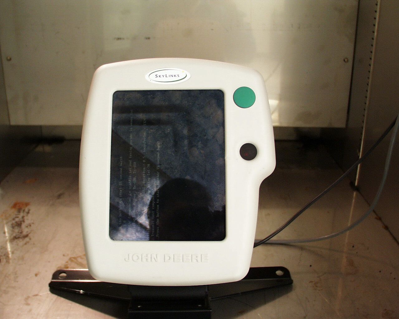
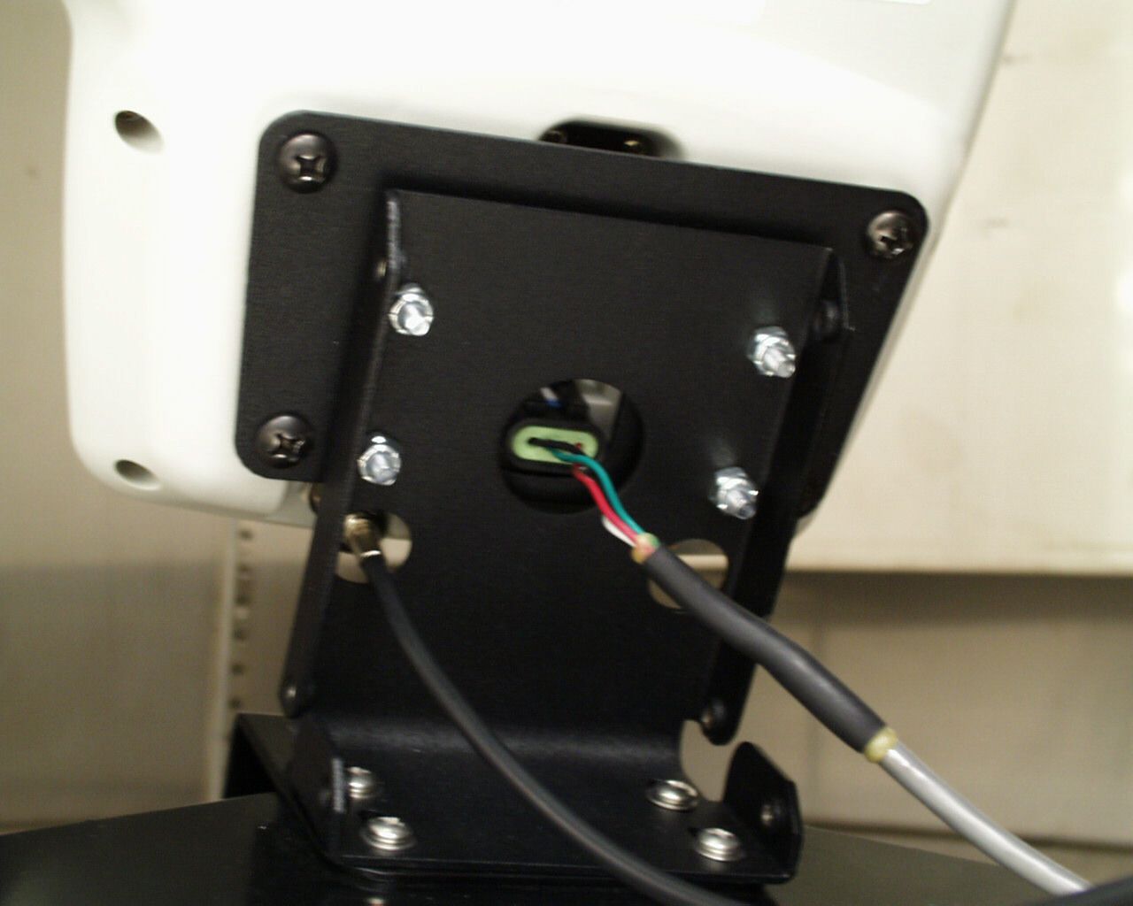
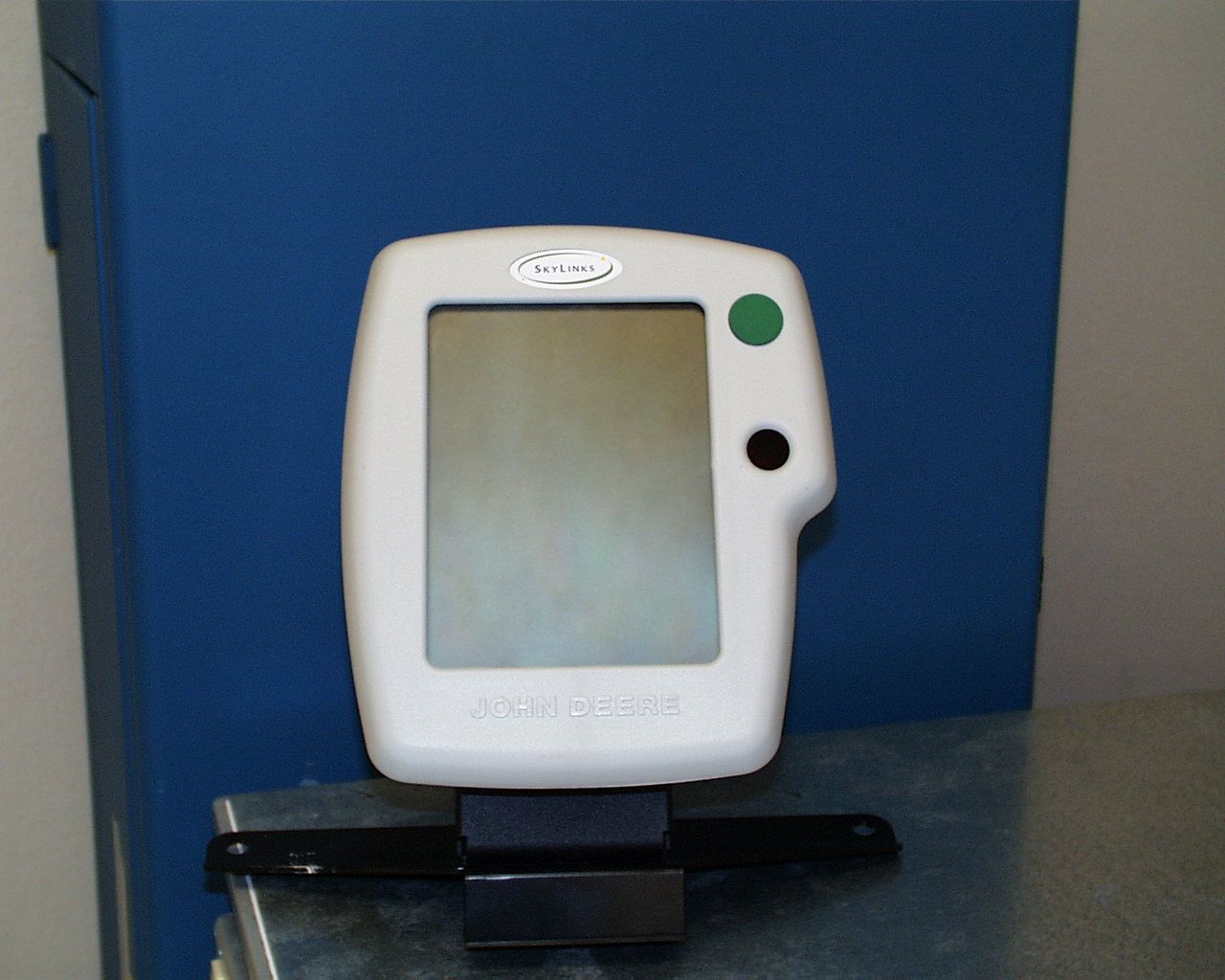
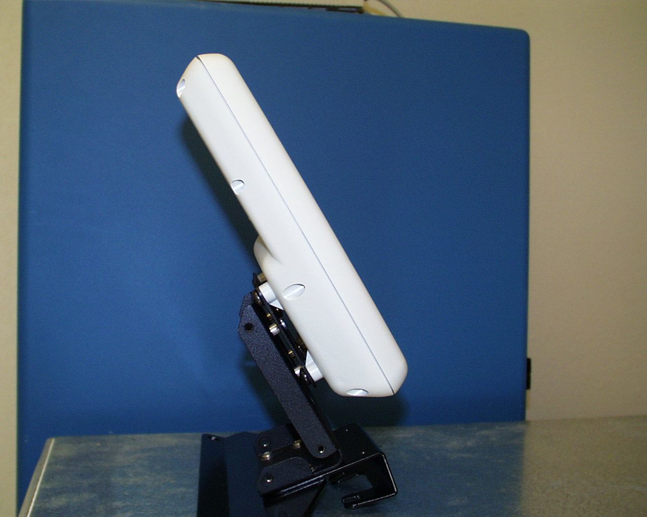
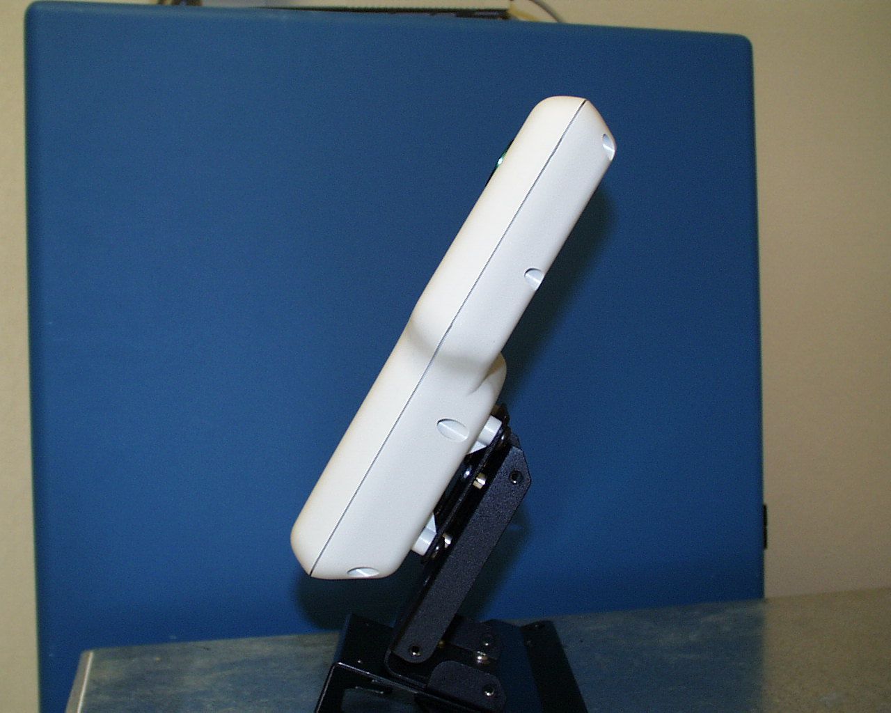
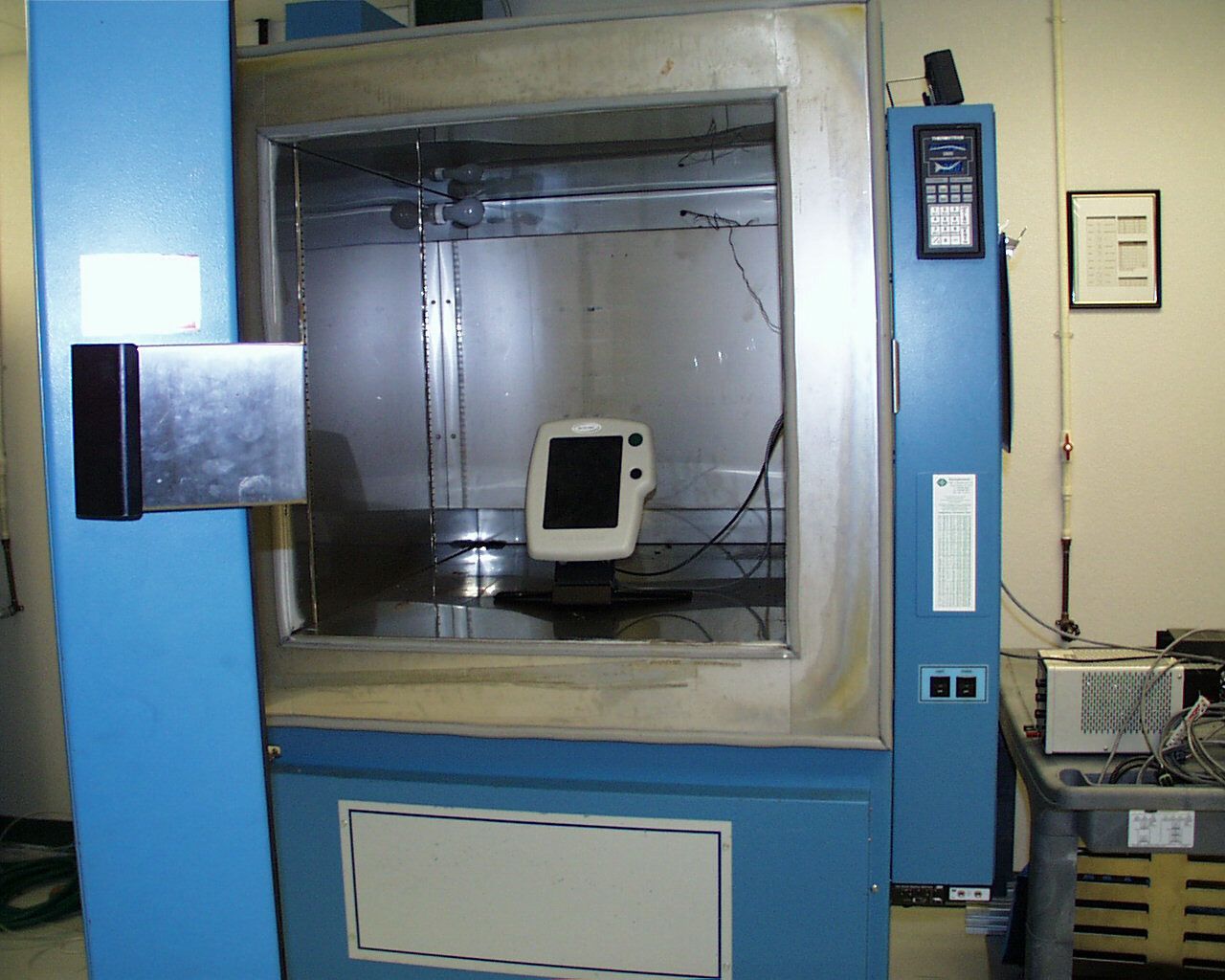
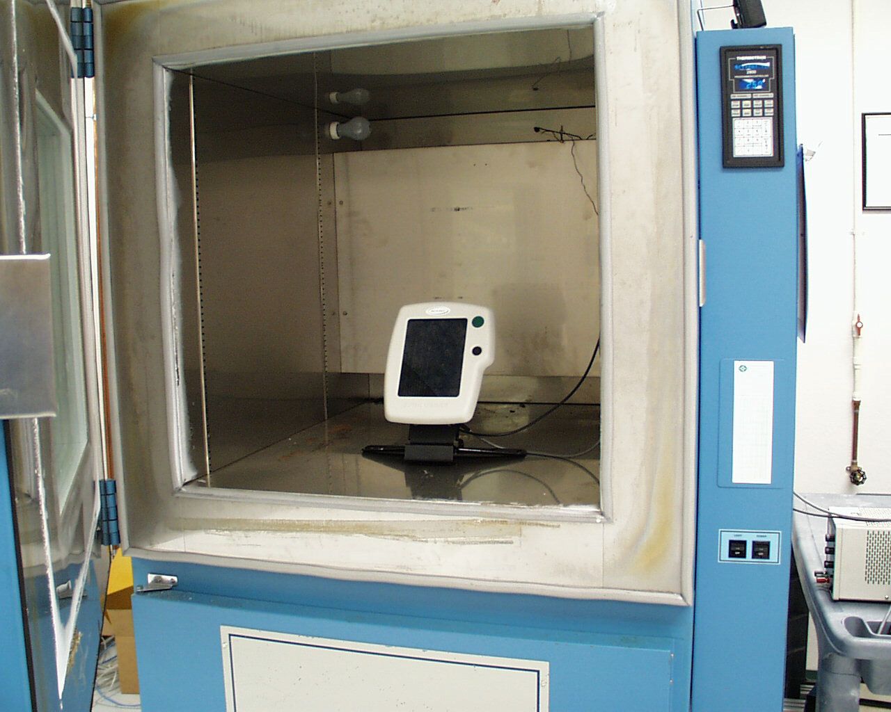
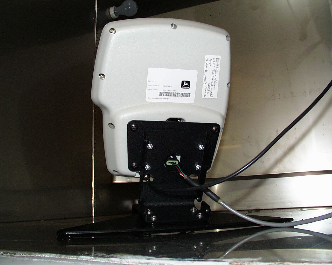
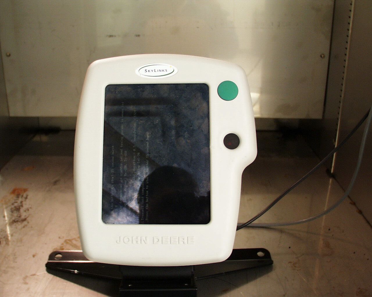
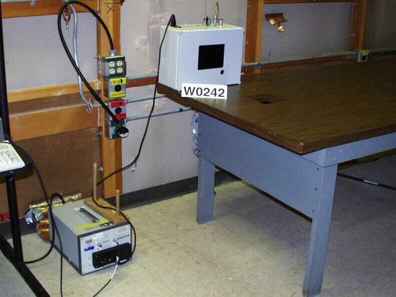
NTV-JDGT-0001Skylinks Head Unit and Skylinks Power Supply
Deere & Company dba ISG - Electronic Systems
Click to zoom
Application Details
- Equipment Class
- TNB - Licensed Non-Broadcast Station Transmitter
- Date of Grant
- Mar 04, 2001
- Application Purpose
- Original Equipment
- Date of Application
- Sep 24, 2000
- Equipment Note
- Skylinks Head Unit and Skylinks Power Supply
- Frequency Range
- 450.00000000 - 470.00000000
- Country
- United States
Documents & Files
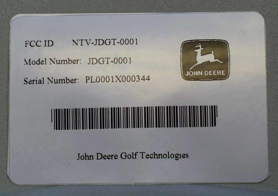
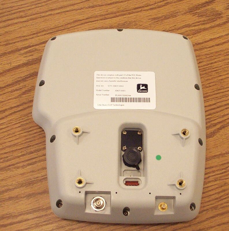
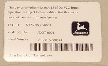
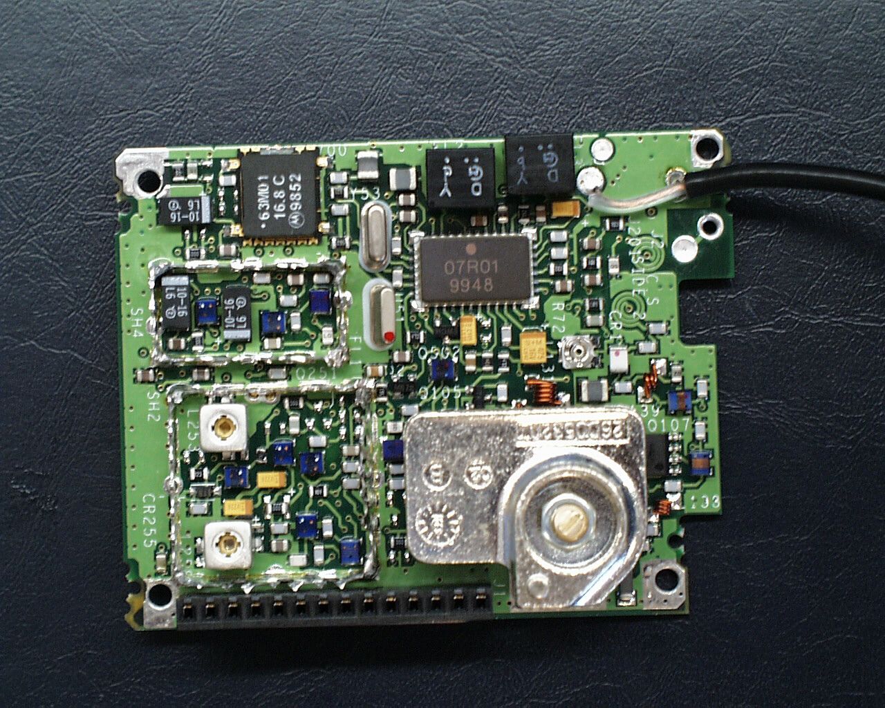
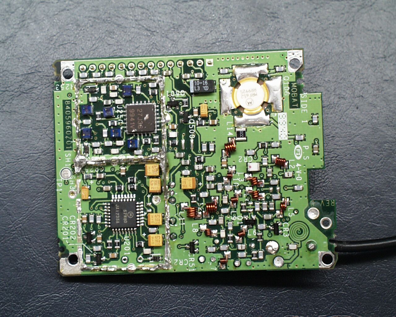
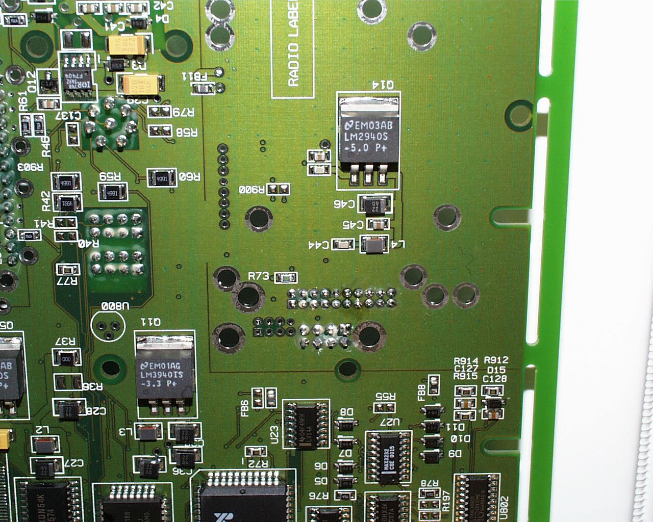
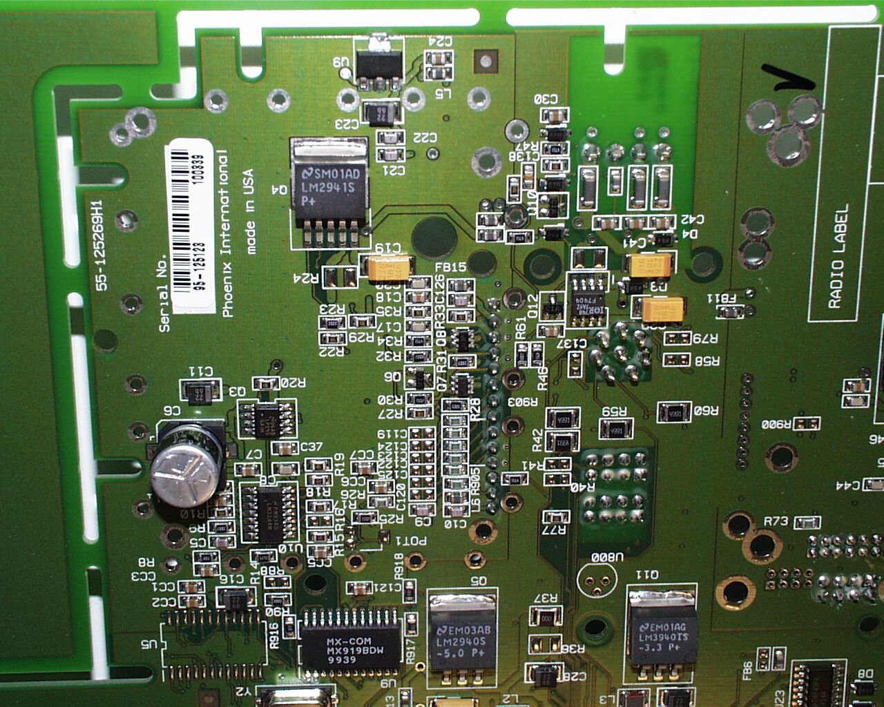
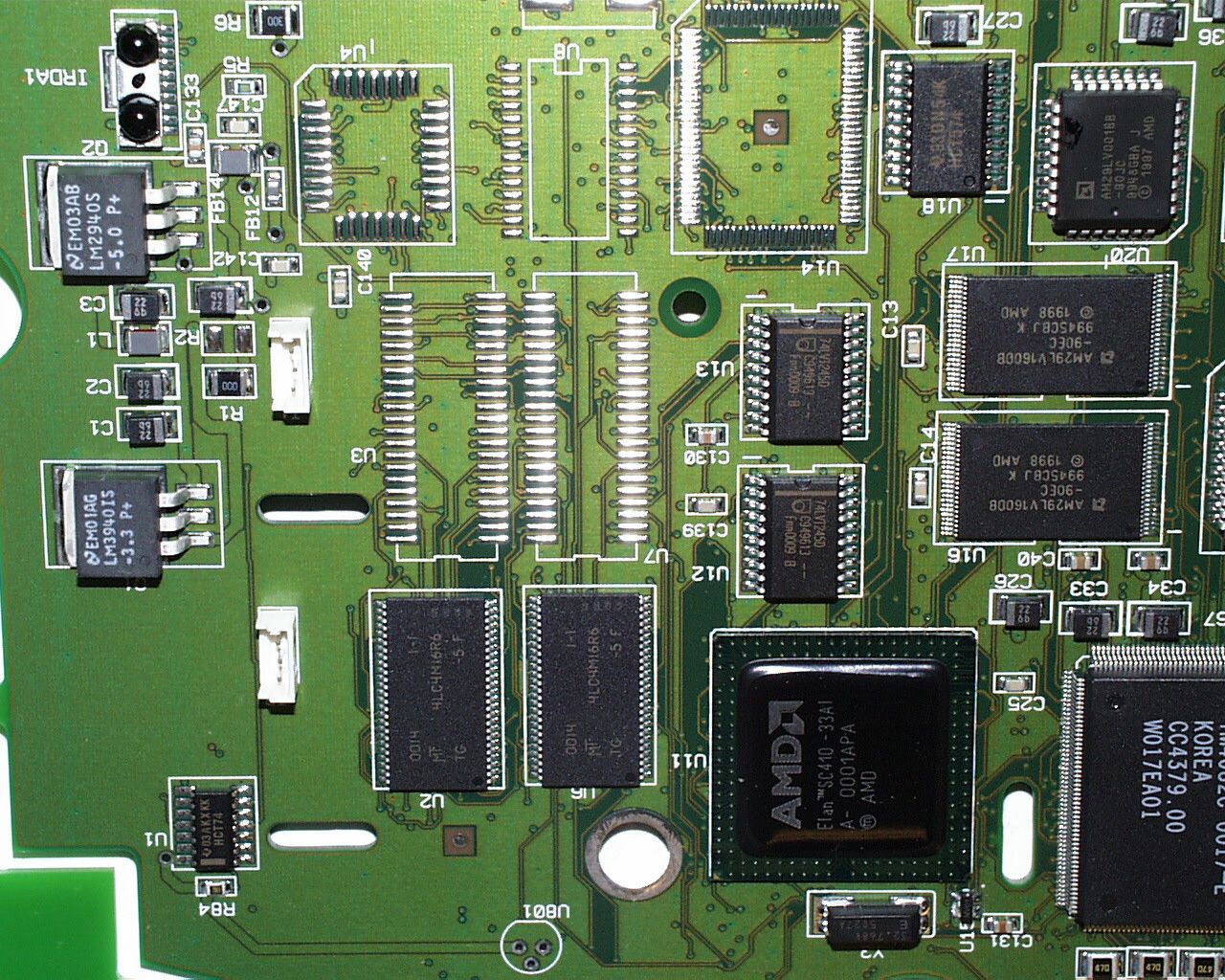
Document Text
Text extracted from the exhibit documents filed with the FCC. Open a document above to read the original.
Users Manual
John Deere Golf Technologies Installation Manual Generation 4 John Deere Golf Technologies 3159 Royal Drive, Suite 320 Alpharetta, GA 30022 1-877-298-8515 May 00, 2000 Installation SkyLinks (May 00, 2000) Installation Instructions2 Safety.....................................................................................................................................................................................................3 Overview................................................................................................................................................................................................5 General System...........................................................................................................................................................................5 Parts List...............................................................................................................................................................................................6 Bill of Material Numbers....................................................................................................Error! Bookmark not defined. Club Car.................................................................................................................................Error! Bookmark not defined. EZ-GO....................................................................................................................................Error! Bookmark not defined. Yamaha..................................................................................................................................Error! Bookmark not defined. Sub-Assembly Part Numbers...............................................................................................................................................6 Club Car Part Numbers..............................................................................................................................................................6 EZ-GO Assembly Numbers......................................................................................................................................................8 Yamaha Assembly Numbers.....................................................................................................................................................9 Service Part Numbers............................................................................................................................................................10 Parts Included in Bill of Material...........................................................................................................................................11 Club Car Sub-Assemblies........................................................................................................................................................11 EZ-GO Sub-Assemblies..........................................................................................................................................................17 Yamaha Sub-Assemblies.........................................................................................................................................................22 TOOLS AND EQUIPMENT....................................................................................................................................................27 Basic System Layout ........................................................................................................................................................................28 Installation Instructions.................................................................................................................Error! Bookmark not defined. Overview of Generic UHF Antenna Bracket Installation....................................Error! Bookmark not defined. Club Car UHF Pre 2000 Bracket Installation..........................................................Error! Bookmark not defined. Club Car UHF Post 2000 Bracket Installation........................................................Error! Bookmark not defined. EZ-GO UHF Bracket Installation................................................................................Error! Bookmark not defined. Yamaha UHF Bracket Installation..............................................................................Error! Bookmark not defined. Overview of Generic GPS Antenna Bracket Installation................................................Error! Bookmark not defined. Club Car Pre 2000 GPS Bracket Installation...........................................................Error! Bookmark not defined. Club Car Post 2000 GPS Bracket Installation.........................................................Error! Bookmark not defined. EZ-GO GPS Bracket Installation................................................................................Error! Bookmark not defined. Yamaha GPS Bracket Installation...............................................................................Error! Bookmark not defined. Overview of Generic Power Harness Installation..............................................................Error! Bookmark not defined. Club Car Power Harness Installation.........................................................................Error! Bookmark not defined. EZ-GO Power Harness Installation............................................................................Error! Bookmark not defined. Yamaha Power Harness Installation...........................................................................Error! Bookmark not defined. Overview of Generic Display Unit Bracket Installation..................................................Error! Bookmark not defined. Club Car Display Unit Bracket Installation.............................................................Error! Bookmark not defined. EZ-GO Display Unit Bracket Installation.......................................…
Text truncated - open the document above for the full version.
Users Manual
Installation Instructions Overview of Generic UHF Antenna Bracket Installation FCC Antenna Warning Use of any antenna other than the one provided with this kit may expose the user or nearby persons to radio frequency (RF) emission levels outside the FCC safety guidelines. ß Left (drivers side) and Right side of cart will be identified as someone sitting forward in cart. ß Before doing any work on golf cart, make sure that the key is in the off position. ß Ensure the parking brake is set. ß Remove windshields if installed before beginning as per Cart Manufacture User’s Manual. ß The UHF antenna cable is not attached to the Display Unit during this phase of the installation. Leave cable assemble available for easy access for latter in the installation. Specific UHF Antenna Bracket Installation instructions per cart type (ex. Club Car, EZ-GO, Yamaha), and model. Club Car Pre 2000 UHF Antenna Bracket Installation Parts 1. Bracket / Antenna 2. Antenna whip 3. Phillips Screws (2) 4. Flat Washer (2) 5. Spacer (2) Club Car Completed Pre 2000 UHF Bracket Installation 1 2 3 4 5 Future picture of completed UHF Bracket Installation. Club Car UHF Pre 2000 Bracket Installation 1. Remove right side of cart bracket on hood of cart. 2 7/16 bolts with locking nut. 3. Attach Antenna whip upon completion of UHF antenna Bracket. 1. Mount UHF antenna on right side of cart using the two Phillips head screws, flat washer and sheathing pieces. Important: UHF bracket needs to be isolated from cart ground. FCC Antenna Warning Label While the device is in operation, a separation of at least 500 mm (20 in.) must be maintained between antennae and the body of the user or nearby persons in order to meet the FCC RF exposure guidelines. Future picture of Antenna whip being installed. 4. Route UHF antenna cable down roof support. Placing the first tie strap at the top bend of support, and another every 6-8 inches. Important: Do not pull UHF cable tight at the roof location. Allow a gentle bend to cart frame. = Zip tie location 5. This completes the UHF bracket and UHF cable installation. Note: Leave UHF cable connector end unattached. It will be connected latter in the installation. Club Car Post 2000 UHF Antenna Bracket Installation Parts 1. Antenna 2. Antenna whip 3. Bracket 4. Spacer 5. Phillips Screws (2) 6. Flat Washer (2) Club Car Post 2000 Completed UHF Bracket Installation Future picture of completed UHF Bracket Installation. A future picture of the UHF antenna, antenna whip, bracket, Phillips screws, and flat washer will be inserted. Club Car UHF Post 2000 Bracket Installation 1. Remove left side 7/16 bolts securing roof . 2. Attach screw, washer and plastic sheathing to bracket, and secure Important: UHF bracket needs to be isolated from cart ground. 3. Attach Antenna bracket with screws and lock tight. 5. Attach Antenna cable to bracket, and attach whip. FCC Antenna Warning Label While the device is in operation, a separation of at least 500 mm (20 in.) must be maintained between antennae and the body of the user or nearby persons in order to meet the FCC RF exposure guidelines. 4. Route UHF antenna cable down roof support. Placing the first tie strap at the top bend of support, and another every 6-8 inches. Important: Do not pull UHF cable tight at the roof location. Allow a gentle bend to cart frame. = Zip tie location 5. This completes the UHF bracket and UHF cable installation. Note: Leave UHF cable connector end unattached. It will be connected latter in the installation. EZ-GO UHF Antenna Bracket Installation Parts 1. Antenna 2. Antenna whip 3. Bracket 4. To Be Determined 5. To Be Determined 6. To Be Determined EZ-GO Completed UHF Antenna Bracket Installation A future picture of the UHF antenna, antenna whip, bracket, Phillips screws, and flat washer will be inserted. Future picture of completed EZ-GO UHF Bracket Installation. EZ-GO UHF Bracket Installation 1. Remove right side of cart bracket on hood of cart. Important: UHF bracket needs to be isolated from cart ground. 2. Mounting process to be determined. Future Picture of how bracket should look being mounted with appropriate screws. Future tools required to remove bracket Future picture of bracket Future picture of bracket 2. Attach Antenna whip upon completion of UHF antenna Bracket. FCC Antenna Warning Label While the device is in operation, a separation of at least 500 mm (20 in.) must be maintained between antennae and the body of the user or nearby persons in order to meet the FCC RF exposure guidelines. Future picture of Antenna whip being installed. 4. Route UHF antenna cable down roof support. Placing the first tie strap at the top bend of support, and another every 6-8 inches. Important: Do not pull UHF cable tight at the roof location. Allow a gentle bend to cart frame. = Zip tie location 5. This completes the UHF bracket and UHF cable installation. Note: Leave UHF cable connector end unattached. It will be connected latter in the installation. Yamaha UHF Antenna Bracket Installation Parts Future picture of bracket with bend of UHF antenna. Future picture of cart with tie strap locations. 1. Antenna 2. Antenna whip 3. Bracket 4. To Be Determined 5. To Be Determined 6. To Be Determined Yamaha Completed UHF Antenna Bracket Installation A future picture of the UHF antenna, antenna whip, bracket, Phillips screws, and flat washer will be inserted. Future picture of completed Yamaha UHF Bracket Installation. Yamaha UHF Bracket Installation 1. Remove right side of cart bracket on hood of cart. Important: UHF bracket needs to be isolated from cart ground. Future picture of bracket Future picture of bracket Future picture of bracket with tools required 3. Attach Antenna whip upon completion of UHF antenna Bracket. 4. Route UHF antenna cable 2. Mounting process to be determined. FCC Antenna Warning Label While the device is in operation, a separation of at least 500 mm (20 in.) must be maintained between antennae and the body of the user or nearby p…
Text truncated - open the document above for the full version.
Users Manual
• Verify the positive lead and ground of cart. • When routing the Power Harness cable make sure the cable does not interfere with cart operation. • The cable should be isolated of working parts of the cart. • Two installers are required to remove seat to avoid back injuries. Parts Required for Assembly of Power Supply Bracket and Mounting Power Supply 1. Power Harness 2. Power Supply Bracket 3. Clamp / Phillip head Screw 4. Bolt (4) 5. Power Supply Assembly of Power Supply Bracket and Mounting Power Supply 1. Insert screw into hole on flat side of Power Supply Bracket 2. Start screw into clamp Note: Notch of clamp should be to the inside towards power supply bracket. 2 3 4 5 1 3. Mount Power Supply onto bracket using four bolts. Note: Power Supply connector should be facing towards beveled end of power supply bracket. Club Car Power Harness Installation Parts 1. Power Supply 2. Power Harness 3. Power Supply Bracket Pre Assembled Club Car Completed Power Harness Installation Future picture of power supply mounted on bracket 1 3 2 Future Picture of Club Car Cart with completed Power Harness Installed Club Car Power Harness Installation Note: Two Persons Should be used to Remove Seat. 1. Remove Seat Note: Be Careful of Battery Acid Build up Around Battery Terminals Note: Frame Ground- Do Not Allow tools to contact from when disengaging battery cable. Never allow a Positive wire to touch the cart frame. 2. Remove Nut on Positive Terminal Lead of battery 3. Attach the Red Ring terminal of power harness to battery 4. Secure the nut back onto Positive Terminal Lead of the battery 5. Secure Fuse holder to cart Note: Make Sure Fuse Holder is in a Vertical Position with Leads Facing Toward the Ground, and the Fuse Holder is Accessible 6. Route Black lead of power harness behind plastic guard of cart 7. Remove the nut on the Ground terminal lead of battery 8. Attach Black Ring terminal of power harness to battery 9. Secure nut back on to ground terminal lead 10. Secure Power Harness connector to Power Supply 11. Mount Power Supply Bracket to cart. Location is left side of battery compartment, in front of batteries. Future picture of seat being removed Future picture of installing black wire of power harness Future picture of power supply being connected to power harness. Future picture of Power Supply location on Club Car. Future picture of installing red wire of power harness 12. Install blue wire to electrical system for key switch. MORE to ADD Mike C. 13. Route Power Harness cable along frame of cart. Securing with tie straps. Note: The cable should be isolated of working parts of the cart. 14. Replace the Seat 15. Remove screw caps on the side of dashboard, and save 16. Loosen screws securing dashboard 17. Pop off top of dashboard by running screwdriver along the top of dash and below frame of cart 18. Bend top right corner of dash inward to get key switch assembly out of dash Note: DO NOT LET KEY SWITCH COME IN CONTACT WITH FRAME OF CART 19. Run screwdriver along bottom side of dashboard to finish removing 20. Sitting on the seat Clip a ½” x ½” notch in the lower right corner of the dashboard. This is to allow enough clearance for the power cable to be ran into the bracket and attach to the head unit. Bend corner inward to get key switch past frame 21. Insert bottom of dashboard back into place Note: BE CAREFUL NOT TO ALLOW THE KEYSWITCH TO COME IN CONTACT WITH THE CART FRAME. 22. Pull about 1’ 6” of cable out to be ran for the Display Unit 23. Bend right corner inward to allow key switch room to be inserted 24. Place left corner in place 25. Push top part of dash into place 26. Tighten screws 27. Replace caps Future picture depicturing route of cable. A. Remove cap B. Loosen screw C. Insert screwdriver here to remove dash. D. Run screwdriver along white line C. Remove cap D. Loosen screw EZ-GO Power Harness Installation Parts 1. Power Harness 2. Power Supply Pre-Assembled 3. Tie Strap EZ-GO Completed Power Harness Installation Future picture of Power harness, Power supply bracket, clamp, Phillips head screw, and four bolts. Future Picture of Club Car Cart with completed Power Harness Installed EZ-GO Power Harness Installation Process has not been defined at this time. Yamaha Power Harness Installation Parts 1. Power Harness 2. Power Supply Pre-Assembled 3. Tie Strap Yamaha Completed Power Harness Installation Future picture of Power harness, Power supply bracket, clamp, Phillips head screw, and four bolts. Future Picture of Club Car Cart with completed Power Harness Installed Yamaha Power Harness Installation Process has not been defined at this time. Overview of Generic Display Unit Bracket Installation • Left (drivers side) and Right side of cart will be identified as someone sitting forward in cart. • Make sure key switch is in the off position. • Ensure the parking brake is set. • When routing the Power Harness cable make sure the cable does not interfere with cart operation. • The cable should be isolated of working parts of the cart. Specific Display Unit Bracket Installation instructions per cart type ex. (Club Car, EZ-GO, Yamaha) Club Car Display Unit Bracket Installation Parts 1. Display Unit Bracket 2. Display Unit Support Cover 3. Display Center Support Club Car Completed Display Unit Bracket Installation Future picture of Display Unit bracket with call outs. Future picture of completed Display Unit Bracket Installation. Club Car Display Unit Bracket Installation 1. Remove four Screws securing the Display Unit Support Cover 2. Install Mounting Bracket on left side of cart 3. Run Power Harness cable behind mounting bracket and into hole in center piece 4. Re-Install Display Unit Center Piece. Future picture of support cover removed Future picture of mounting bracket on cart. Future picture of routing power harness cable into display unit bracket Future picture of re-installing display unit center piece. EZ-GO Display Unit Bracket Installation Parts Display Bracket Installation parts…
Text truncated - open the document above for the full version.
Users Manual
John Deere Golf Technologies Installation Manual Generation 4 John Deere Golf Technologies 3159 Royal Drive, Suite 320 Alpharetta, GA 30022 1-877-298-8515 Dec 04, 2000 1 Club Car Post 2000 Club Car Post 2000 Club Car Post 2000 Club Car Post 2000 – –– – Table of Contents Table of Contents Table of Contents Table of Contents Overview OverviewOverview Overview ................................ ................................................................ ................................................................ ................................................................ ................................................................ ................................................................ ....................................... .............. ....... 2 22 2 Parts List Parts ListParts List Parts List................................ ................................................................ ................................................................ ................................................................ ................................................................ ................................................................ ....................................... .............. ....... 3 33 3 Assembly Part Numbers ....................................................................................................................................................... 3 Service Part Numbers ........................................................................................................................................................... 5 Parts Included in Bill of Material......................................................................................................................................... 6 Tools and Equipment ............................................................................................................................................................ 9 Basic System Layout Basic System Layout Basic System Layout Basic System Layout ................................ ................................................................ ................................................................ ................................................................ ................................................. .................................. ................. 10 1010 10 Installation Instructions Installation InstructionsInstallation Instructions Installation Instructions................................ ................................................................ ................................................................ ................................................................ .............................................. ............................ .............. 11 1111 11 Overview of Club Car Post 2000 UHF Antenna Bracket Installation................................................................. 11 Club Car UHF Post 2000 Bracket Installation............................................................................................................... 13 Overview of Club Car Post 2000 GPS Antenna Bracket Installation ............................................................................. 17 Club Car Post 2000 GPS Bracket Installation................................................................................................................ 18 Overview of Club Car Post 2000 Power Harness Installation ......................................................................................... 21 Club Car Power Harness Installation...............................................................................................................................24 Overview of Club Car Post 2000 Display Unit Bracket Installation ............................................................................... 28 Club Car Display Unit Bracket Installation.................................................................................................................... 29 Overview of Generic Display Unit Installation ................................................................................................................. 32 Club Car Display Unit Installation................................................................................................................................... 33 Trouble Shooting Trouble ShootingTrouble Shooting Trouble Shooting ................................ ................................................................ ................................................................ ................................................................ ......................................................... .................................................. ......................... 35 3535 35 2 Live With Safety Please before returning cart to customer, make sure cart is Functioning properly, especially the safety systems. Install all safety guards and shields. Overview General System SkyLinks is a golf management / information system. It provides valuable information to the golfer and the course manager through such technologies as satellite navigation and digital radio communications. The main components of SkyLinks are the computer display units on each golf cart, a central computer server in the clubhouse, workstation computer(s), and a communications system to tie it all together. Golf cart computers The golf cart computer performs the following functions: Vehicle tracking with GPS (Global Positioning System) Data feed to/from the clubhouse oAdvertising images oText messages from the clubhouse oDisplay tailored to the golfer to display: ! Course map display ! Accurate yardage information ! Pro's tips 3 Parts List Assembly Part Numbers Part numbers are assigned by Phoenix International, and are subject to change without notice Item Part Number Description HEAD UNIT ASSEMBLY JDGT-0001 Display Unit POWER SUPPLY JDGT-0002 Power Supply BKT, PWR SUPPLY – CLUB…
Text truncated - open the document above for the full version.
Attestation Statements
TÜV PRODUCT SERVICE INC 19333 WILD MOUNTAIN ROAD TAYLORS FALLS, MINNESOTA 55084-1786 ENGINEERING STATEMENT For Certification of Phoenix International Skylinks Head Unit and Skylinks Power Supply Model No: JDGT-0001 Skylinks Head Unit JDGT-0002 Skylinks Power Supply I am an Electromagnetic Compatibility Engineer for TÜV PRODUCT SERVICE INC, Taylors Falls, Minnesota. My education and experience are a matter of record with the Federal Communications Commission. TÜV PRODUCT SERVICE INC has been authorized by Ahmad Mahin Fallah, Senior Engineer, of Phoenix International, to make Certification measurements on the Skylinks Head Unit and Skylinks Power Supply. These tests were made by me or under my supervision at our Wild River Laboratory which is on file with the FCC under Paragraph 2.948 of the FCC Rules. Test data required by the TCB is included in this report. It is submitted that the above equipment meets FCC Part 90 Requirements and Certification is hereby requested. Joel T Schneider Minnesota Wild River Lab TÜV Product Service jschneider @ tuvps.com Dated: 11 September 2000
Attestation Statements
TÜV MANAGEMENT SERVICEPhone: (651) 631 2487 TÜV PRODUCT SERVICE INC.Fax: (651) 638 0285 1775 Old Highway 8 NW, Suite 104email [email protected] New Brighton MN 55112-1891http:://www.tuvglobal.com Divisions of TÜV America Inc., a subsidiary of TÜV Süddeutschland and TÜV Nord Group TÜV PRODUCT SERVICE INC 19333 WILD MOUNTAIN ROAD TAYLORS FALLS, MINNESOTA 55084-1786 ENGINEERING STATEMENT For Certification of Phoenix International Skylinks Head Unit and Skylinks Power Supply Model No: JDGT-0001 & JDGT-0002 I am an Electromagnetic Compatibility Engineer for TÜV PRODUCT SERVICE INC, Taylors Falls, Minnesota. My education and experience are a matter of record with the Federal Communications Commission. TÜV PRODUCT SERVICE INC has been authorized by Ahmad Mahin Fallah, Senior Engineer, of Phoenix International, to make Certification measurements on the Skylinks Head Unit and Skylinks Power Supply. These tests were made by me or under my supervision at our Wild River Laboratory which is on file with the FCC under Paragraph 2.948 of the FCC Rules. Test data required by the TCB is included in this report. It is submitted that the above equipment meets the FCC Part 90, Subpart C Requirements and Certification is hereby requested. Joel P Peltier Minnesota EMC Manager TÜV Product Service [email protected] Dated: 21 August 2000
Block Diagram
Skylinks Head Unit +33VDC** (TNC) (Type-N) Host PC Initial programming of Ashtech sensor and changes to NETMASTR.INI must take place at installation. In normal operation, the Head Unit maintains a bidirectional link with the Host PC. (All front panel data connectors DB-9.) PWR LED Power Input interface, 3 Amp fuses on both Line and Neutral 120VAC GPSUHF ** Unregulated SAT LED 09/10/00 RWY Po=4W (Pulsed) Lightning Arrestor: DC Blocking Lightning Arrestor: Must Pass DC Skylinks Power Supply Bulk DC Supply +6VDC +13VDC LED/RS-232 Driver Board GPS Config.SpareMain Ashtech G12 GPS Sensor Denotes Permanent Connections Denotes Temporary Connections TX Frequency: 450-470MHz RX Frequency: 450-470MHz RX LO Frequency: 404.9MHz-424.9MHz Modem IC Osc: 9.8304MHz Video IC Osc: 14.3181MHz fund., 20.0MHz derived CPU Osc: 32.768kHz fund., 33/66MHz derived
Block Diagram
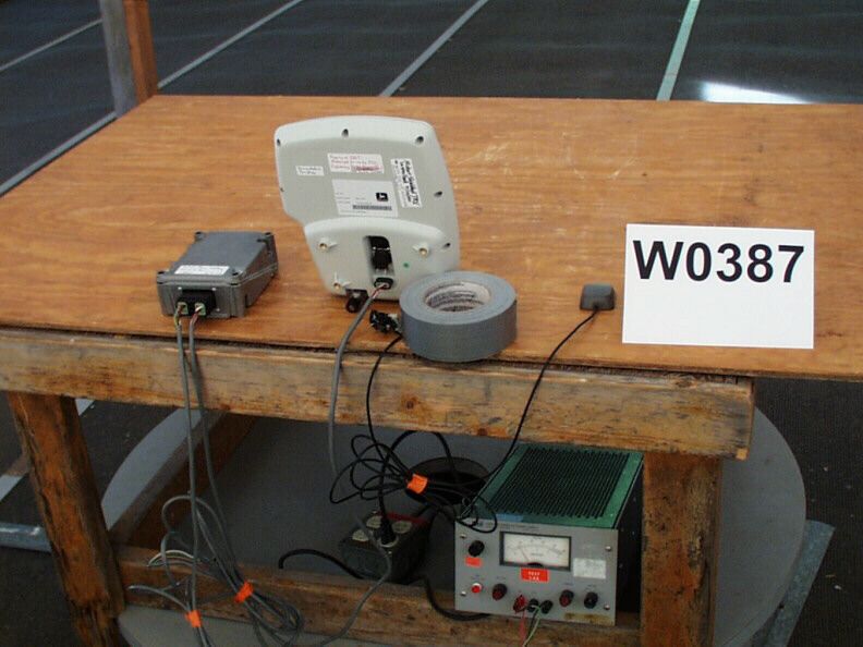
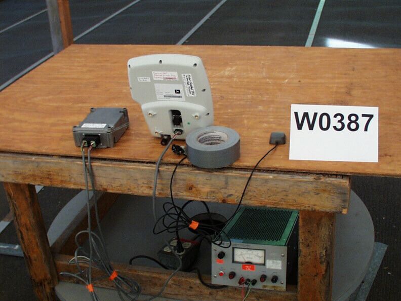
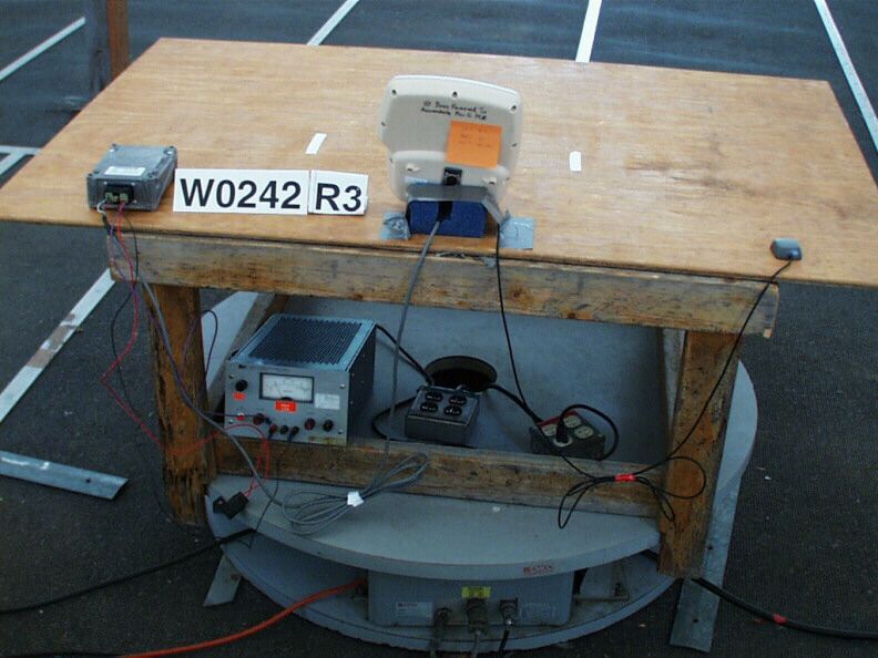
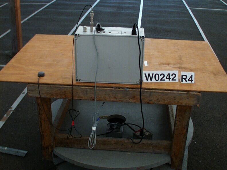
Active GPS Antenna RG-174 coax wrapped in non-inductive “bow-tie” SMA TNC 50-Ohm Terminator For UHF Ant. Port EUT Skylinks Power Supply +13VDC, +6VDC, Key In, Ground Provided by Supply (Items inside dotted box were on top of turntable for testing.) (Satellites still received through nonmetallic roof of test structure.) + _ Vin Gnd (Benchtop Supply Under Turntable) +13.8VDC
Cover Letter(s)
BABT PRODUCT SERVICE TCB For TCB use only TCB FORM 731 APPLICATION FOR EQUIPMENT AUTHORIZATION SECTION I - ALL ITEMS IN THIS SECTION MUST BE COMPLETED Check Column (A) for the applicable service. Enter in Column (B) the Fee. FOR TCB USE ONLY FOR TCB USE ONLY TOTAL AMOUNT REMITTED FOR THIS SUBMITTAL Add amounts shown in column B and enter the total here. This amount should equal your remittance. TCB Form 731 - Page 1 of 3 ( JUNE 2000) 4. Name, Title and Mail Stop, if any, of person at the applicant's address to receive grant, or for contact: (See instructions) Ahmad Mahin Fallah – Sr. EMC Engineer 5.(a) Telephone No. (Area/Country/City code, No. and Ext.) 701-277-6322 1. Applicant's complete, legal business name Phoenix International Check here if this is a change in name and/or address not previously reported (See 47 CFR §2.934) 2. Applicant’s mailing address (Line 1) 1441 44 th Street NW Applicant’s mailing address (Line 2) (if required) City Fargo TCB Use Only Equipment Code: Engineer: Examiner: State or Country (if foreign address) 3. FCC ID: (b) Equipment Product Code (a) Grantee Code (14 characters maximum, show zeros as Ø) North Dakota ZIP/Postal Code (b) FAX No. (Area/Country/City code and No.) 701-277-6206 (c) Internet e-mail address: SECTION II - See Request for Quotation for Fees. FEE DUE FOR COLUMN (A) $ $ 995.00 $ $ $ 995.00 (A) (B) 58102 NTV –JDGT-0001 CONFIDENTUALITY x TRANSMITTERS & TRANSCEIVERS RECEIVERS CLASS II PERMISSIVE CHANGE $ PAPER FILING FOR LICENSED AND UNLICENSED DEVICES 1.(a) Instead of Applicant, TCB is authorized to mail original Grant to: (See instructions) Firm name, Number, street, City, State/Country,N/A ZIP/Postal Code (b) Name, Title and Mail Stop, if any, of person at above address to receive Grant: (If 1.(a) is completed, this Item must be completed.) 2.(a) Technical contact: Joel T. Schneider Firm name,TÜV Product Service Inc Contact person,19333 Wild Mountain Road Number, street,Taylors Falls MN 55084-1786 City, State/Country, ZIP/Postal Code (b) Telephone No. (Area/Country/City code, No. and Ext.) (651) 583-3322 (c) FAX No. (Area/Country/City code and No.) ( 651) 638-0298 7. EQUIPMENT SPECIFICATIONS: (See instructions) (a) Frequency range in MHz (b) Rated RF power output in watts (c) Frequency tolerance %, Hz, ppm (d) Emission designator (See 47 CFR §2.201 and §2.202) (e) M…
Text truncated - open the document above for the full version.
Contact Information
Applicant
Andrew J Norby(Engineering Manager, Electronic Systems)
Technical Contact
TUV PRODUCT SERVICE INCJoel T Schneider
[email protected]651 583-3322
19333 Wild Mountain Road · Taylors Falls, Minnesota · United States
Non-Technical Contact
TUV PRODUCT SERVICE INCSusan A Becker
[email protected]651 583-3322
Test Firm
TUV SUD America - Product ServiceJoel Schneider
Technical Specifications
| # | Rule Parts | Frequency Range | Power Output | Emission | Tolerance |
|---|---|---|---|---|---|
| 1 | 90 | 450 MHz - 470 MHz | 4 W | 19K6F1D | 2.5000000000 ppm |
Other Applications from Deere & Company dba ISG - Electronic Systems

NTV-90136746
Jun 19, 2005Doppler Effect Flow Sensor
Equipment Class
FDS - Part 15 Field Disturbance Sensor
NTV-90137673
Jun 19, 2005Doppler Effect Ground Speed Sensor
Equipment Class
FDS - Part 15 Field Disturbance Sensor
NTV-JDSTG-PSA01
Feb 14, 2001AccuSpeed Doppler Effect Speed Sensor
Equipment Class
FDS - Part 15 Field Disturbance Sensor