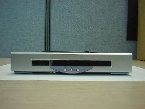
NU2HST-2000SCDigital Satellite Receiver
Handan BroadInfoCom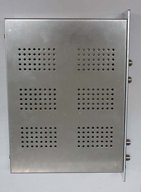
Click to zoom
Application Details
- Equipment Class
- JBP - Part 15 Class B Computing Device Peripheral
- Date of Grant
- Feb 20, 2002
- Application Purpose
- Original Equipment
- Date of Application
- Feb 20, 2002
- Equipment Note
- Digital Satellite Receiver
- Frequency Range
- 47.00000000 - 862.00000000
- Company
- Handan BroadInfoCom
- Country
- South Korea
Documents & Files
Document Text
Text extracted from the exhibit documents filed with the FCC. Open a document above to read the original.
Users Manual
1 CONTENTS 1.Safety Instructions2 2.Specifications6 3.Assembling Instructions8 4.Descriptions11 5.Installation16 6.Channel & Frequency Table 19 •Read Instructions- All the safety and operating instructions should be read before the product is operated. •Retain Instructions- The safety and operating instructions should be retained for future reference. •Heed Warnings- All warning on the product in the operating instructions should be adhered to. •Follow Instructions- All operating and use instructions should be followed. •Cleaning- Unplug this product from the wall outlet before cleaning. Do not use liquid cleaners or aerosol cleaners. Use a damp cloth for cleaning. •Attachments- Do not use attachments not recommended by the product manufacturer as they may cause hazards. •Water and Moisture- Do not use this product near water – for example, near bath tub, wash bowl, kitchen sink, or laundry tub; in a wet basement; or near a swimming pool; and the like. •Accessories- Do not place this product on an unstable cart, stand, tripod, bracket, or table. The product may fall, causing serious injury to a child or adult, and serious damage to the product. Use only with a cart, stand, tripod, bracket, or table recommended by the manufacturer, or sold with the product. Any mounting of the product should follow the manufacturer’s instructions, and should use a mounting accessory recommended by the manufacturer. To prevent electric shock, match wide blade of plug to wide slot, fully insert. To prevent fire or electric shock, Do not expose this appliance to rain or moisture. WARNING WARNING CAUTION CAUTION Portable cart warning • A product and cart combination should be moved with care. Quick stops, excessive force, and uneven surfaces may cause the product and cart combination to overturn. •Ventilation- Slots and openings in the cabinet are provided for ventilation and to ensure reliable operation of the product and to product it from overheating, and these openings must not be blocked or covered. The openings should never be blocked by placing the product on a bed, sofa, rug, or other similar surface. This product should not be placed in a built-in installation such as a bookcase or rack unless proper ventilation is provided or the manufacturer’s instructions have been adhered to. •Power Sources- This product should be operated only from the type of power source indicated on the marking label. If you are not sure of the type of power supply to your home, consult your product dealer or local power company. For products intended to operate from battery power, or other source, refer to the operating instructions. The lighting flash with arrowhead symbol, within an equilateral triangle is intended to alter the user to the presence of uninsulated “dangerous voltage” within the product’s enclosure that may be of sufficient magnitude to constitute a risk of electric shock o persons. The exclamation point within a equilateral triangle is intended to alert the user to the presence of important operating and maintenance(Servicing) instruction in the literature accompanying the appliance. CAUTION : TO REDUCE THE RISK OF ELECTRIC SHOCK. DO NOT REMOVE COVER (OR BACK). NO USER SERVICEABLE PARTS INSIDE REFER SERVICING TO QUALIFIED SERVICE PERSONNEL 2 1. Safety Instructions Example of Antenna grounding as per National Electric Code, ANSI/NFPA 70 (NEC – National Electrical Code) ANTENNA LEAD IN WIRE ANTENNA DISCHARGE UNIT (NEC SECTION 810-20) GROUNDING CONDUCTORS (NEC SECTION 810-21) GROUND CLAMPS POWER SERVICE GROUNDING ELECTRODE SYSTEM (NEC AR 250, PART H) GROUND CLAMP ELECTRIC SERVICE EQUOPMENT Note to CATV System Installer This reminder is provided to call the CATV system installer’s attention to Article 820-40 of the NEC that provides guidelines for proper grounding and, in particular, specifies that the cable ground shall be connected to the grounding system of the building, as close to the point of cable entry as practical. •Grounding or Polarization- This product may be equipped with a polarized alternating-current line plug (a plug having one blade wider than the other). This plug will fit into the power outlet only one way. This is a safety feature. If you are unable to insert the plug fully into the outlet, try reversing the plug. If the plug should still fail to fit, contact your electrician to replace your obsolete outlet. Do not defeat the safety purpose of the polarized plug. •Alternate Warnings- This product is equipped with a three-wire grounding-type plug, a plug having a third (grounding) pin. This plug will only fit into a grounding-type power outlet. This is a safety feature. If you are unable to insert the plug into the outlet, contact your electrician to replace your obsolete outlet. Do not defeat the safety purpose of the grounding-type plug. •Power-Cord Protection- Power-supply cords should be routed so that they are not likely to be walked on or pinched by items placed upon or against them, paying particular attention to cords at plugs, convenience receptacles, and the point where they exit from the product. •Productive Attachment Plug- The product is equipped with an attachment plug having overload protection. This is a safety feature. See Instruction Manual for replacement or resetting of protective device. If replacement of the plug is required, be sure the service technician has used a replacement plug specified by the manufacturer that has the same overload protection as the original plug. •Outdoor Antenna Grounding- If an outside antenna or cable system is connected to the product, be sure the antenna or cable system is grounded so as to provide some protection against voltage surges and built-up static charges. Article 810 of the National Electrical Code, ANSI/NFPA 70, provides information with regard to proper grounding of the mast and supporting structure, grounding of the lead-in wire to an antenna discharge unit, size of grounding conductors, location of antenna- discharge unit, co…
Text truncated - open the document above for the full version.
Block Diagram
QPSK TO QAM MAIN BLOCK DIAGRAM TUNER LOOP IF SIGNAL INPUT LNB-output 18V(400m) LOOP MPEG TS MICOM CONTROL QPSK DEMOD QAMMOD MODULATOR & UP/DOWN CONVERTER QAM SIGNAL OUTPUT 47MHz~862MHz CONTROL UNIT CIRCUIT DIAGRAM NOHSM-K2001G CIRCUIT DIAGRAM NOHST-K2000K QAM MODULATOR & UP/DOWN CONVERTER BLOCK DIAGRAM BPF QAM-LINK MODULATOR IC UP-converter PLL DATA CLK 2 ’ st IF OUTPUT LEVEL VARIABLE AMP MIXER PLL DATA CLK VCO VT VT MPEG2 TS 1 ’ st IF QAM SIGNAL OUTPUT 47MHz~862MHz CIRCUIT DIAGRAM NO HST-K2000K
Block Diagram
1.BLOCK DIAGRAM AC 90~ 260V INPUT EMI FILTER REFLECTER & FILTER SWITCHING IC (70KHz) TRANS REFLECTER & FILTER DC OUTPUT OPTO COUPLER
ID Label/Location Info
HST-2000SC HSP-2000SC Label Location
Test Report
Applicant: Handan BoradInfoCom Co., Ltd. FCC ID: NU2HST-2000SC Report #: H\Handan\1182ZBK1\1182ZBK1TestReport.doc Page #: Table of Contents TABLE OF CONTENTS LIST APPLICANT: HANDAN BroadInfoCom Co., Ltd. FCC ID: NU2HST-2000SC TEST REPORT CONTAINING: PAGE 1......TEST EQUIPMENT LIST PAGE 2......TEST PROCEDURES PAGE 3-5....RADIATION INTERFERENCE TEST DATA PAGE 6-8....POWER LINE CONDUCTED INTERFERENCE PAGE 9......OUTPUT TERMINAL CONDUCTED SIGNAL LEVEL EXHIBITS CONTAINING: EXHIBIT 1............FCC ID LABEL SAMPLE EXHIBIT 2............SKETCH OF FCC ID LABEL EXHIBIT 3............SCHEMATIC – MAIN EXHIBIT 4............SCHEMATIC – POWER SUPPLY EXHIBIT 5............BLOCK DIAGRAM – MAIN EXHIBIT 6............BLOCK DIAGRAM – POWER SUPPLY EXHIBIT 7............USERS MANUAL EXHIBIT 8............EXTERNAL PHOTOGRAPH – MAIN EXHIBIT 9............EXTERNAL PHOTOGRAPH – POWER SUPPLY EXHIBIT 10...........INTERNAL PHOTOGRAPH - MAIN EXHIBIT 11...........INTERNAL PHOTOGRAPH – POWER SUPPLY EXHIBIT 12...........TEST SETUP PHOTOGRAPHS EXHIBIT 13...........CIRCUIT DESCRIPTION Applicant: Handan BoradInfoCom Co., Ltd. FCC ID: NU2HST-2000SC Report #: H\Handan\1182ZBK1\1182ZBK1TestReport.doc Page #: 1 of 9 APPLICANT: HANDAN BroadInfoCom Co., Ltd. FCC ID: NU2HST-2000SC TEST EQUIPMENT LIST 1._X_Spectrum Analyzer: HP 8566B-Opt 462, S/N 3138A07786, w/ preselector HP 85685A, S/N 3221A01400, Quasi-Peak Adapter HP 8565OA, S/N 3303A01690 & Preamplifier HP 8449B-OPT H02, S/N 3008A00372 Cal. 8/31/01 Due 8/31/02 2._X_Biconnical Antenna: Eaton Model 94455-1, S/N 1057, Cal. 10/1/01 Due 10/1/02 3.__ Biconnical Antenna: Electro-Metrics Model BIA-25, S/N 1171 Cal. 4/26/01 Due 4/26/03 4.__ Log-Periodic Antenna: Electro-Metrics Model EM-6950, S/N 632 Char. 10/15/01 Due 10/15/02 5.__ Log-Periodic Antenna: Electro-Metrics Model LPA-30, S/N 409 Char. 10/16/01 Due 10/16/02 6._X Log-Periodic Antenna: Electro-Metrics Model LPA-25, S/N 1122 Char. 2/10/01 Due 3/10/02 7.__ Double-Ridged Horn Antenna: Electro-Metrics Model RGA-180, 1-18 GHz, S/N 2319 Cal. 12/19/01 Due 12/19/02 8.__ 18-26.3GHz Systron Donner Standard Gain Horn #DBE-520-20 No Cal Required 9.__ Horn 40-60GHz: ATM Part #19-443-6R No Cal Required 10.__ Line Impedance Stabilization Network: Electro-Metrics Model EM-7820, w/NEMA Adapter S/N 2682 Cal. 3/16/01 Due 3/16/02 11.__ Temperature Chamber: Tenney Engineering Model TTRC, S/N 11717-7 Char. 1/22/02 Due 1/22/03 12.__ Frequency Counter: HP Model 5385A, S/N 3242A07460 Char. 12/11/01 Due 12/11/02 13.__ Peak Power Meter: HP Model 8900C, S/N 2131A00545 Char. 1/26/01 Due 1/26/02 14._X_Open Area Test Site #1-3meters Cal. 12/22/99 15.__ Signal Generator: HP 8640B, S/N 2308A21464 Cal. 11/15/01 Due 11/15/02 16.__ Passive Loop Antenna: EMCO Model 6512, 9KHz to 30MHz, S/N 9706-1211 Char. 7/10/01 Due 7/10/02 17.__ Dipole Antenna Kit: Electro-Metrics Model TDA-30/1-4, S/N 152 Cal. 3/21/01 Due 3/21/02 18.__ AC Voltmeter: HP Model 400FL, S/N 2213A14499 Cal. 10/9/01 Due 10/09/02 19._X_Digital Multimeter: Fluke Model 77, S/N 35053830 Char. 1/8/02 Due 1/8/03 20.__ Oscilloscope: Tektronix Model 2230, S/N 300572 Char. 2/1/01 Due 2/1/02 Applicant: Handan BoradInfoCom Co., Ltd. FCC ID: NU2HST-2000SC Report #: H\Handan\1182ZBK1\1182ZBK1TestReport.doc Page #: 2 of 9 TEST PROCEDURE GENERAL: This report shall NOT be reproduced except in full without the written approval of TIMCO ENGINEERING, INC. RADIATION INTERFERENCE: The test procedure used was ANSI STANDARD C63.4-1992 using a HEWLETT PACKARD spectrum analyzer with a prese- lector. The bandwidth of the spectrum analyzer was 100 kHz with an appropriate sweep speed. The analyzer was calibrated in dB above a microvolt at the output of the antenna. The resolution bandwidth was 100KHz and the video bandwidth was 300kHz. The ambient temperature of the UUT was 80ºF with a humidity of 70%. FORMULA OF CONVERSION FACTORS: The Field Strength at 3m was estab- lished by adding the meter reading of the spectrum analyzer (which is set to read in units of dBuV) to the antenna correction factor sup- plied by the antenna manufacturer. The antenna correction factors are stated in terms of dB. The gain of the Preselector was accounted for in the Spectrum Analyzer Meter Reading. Example: Freq (MHz) METER READING + ACF = FS 33 20 dBuV + 10.36 dB = 30.36 dBuV/m @ 3m ANSI STANDARD C63.4-1992 10.1.7 MEASUREMENT PROCEDURES: The unit under test was placed on a table 80 cm high and with dimensions of 1m by 1.5m. The table used for radiated measurements is capable of continu- ous rotation. When an emission was found, the table was rotated to produce the maximum signal strength. At this point, the antenna was raised and lowered from 1m to 4m. The antenna was placed in both the horizontal and vertical planes. The situation was similar for the conducted measurement except that the table did not rotate. The EUT was setup as described in ANSIC63.4-1992 with the EUT 40 cm from the vertical ground wall. Applicant: Handan BoradInfoCom Co., Ltd. FCC ID: NU2HST-2000SC Report #: H\Handan\1182ZBK1\1182ZBK1TestReport.doc Page #: 3 of 9 APPLICANT: HANDAN BroadInfoCom Co., Ltd. FCC ID: NU2HST-2000SC NAME OF TEST: RADIATION INTERFERENCE RULES PART NUMBER: 15.109 REQUIREMENTS: 30 to 80 MHz: 40.0 dBuV/M @ 3 METERS 88 to 216 MHz: 43.5 dBuV/M 216 to 960 MHz: 46.0 dBuV/M ABOVE 960 MHz: 54.0 dBuV/M TEST RESULTS: A search was made of the spectrum from 30 to 1000 MHz and the measurements indicate that the unit DOES meet the FCC requirements. TEST DATA: Emission Frequency MHz Meter Reading dBuV Ant. Polarity Coax Loss dB Correction Factor dB Field Strength dBuV/m Margin dB DIGITAL EMISSIONS 49.20 22.4 V 0.79 11.99 35.18 4.82 49.20 22.7 H 0.79 11.9 35.48 4.52 53.20 22.8 V 0.83 10.71 34.34 5.66 53.20 18.4 H 0.83 10.71 29.94 10.06 57.30 17.4 V 0.87 9.18 27.45 12.55 57.30 13.6 H 0.87 9.18 23.65 16.35 73.70 27.9 V 1.02 6.66 35.58 4.42 73.70 29.0 H 1.02 6.66 36.68 3.32 122.80 14.5 V 1.29 11.50 27.29 16.21 122.80 15.1 H 1.29 11.50 27.89 15.61 147.40 12.7 V 1.39 16.24 30.…
Text truncated - open the document above for the full version.
Contact Information
Applicant
Lee Yong Kook
Test Firm
Timco Engineering, Inc.S Sanders
Technical Specifications
| # | Rule Parts | Frequency Range | Power Output |
|---|---|---|---|
| 1 | 15B | 47 MHz - 862 MHz | - |
Other Applications from Handan BroadInfoCom
NU2UVR-100N
Feb 13, 2002Digital Satellite Receiver
Equipment Class
HID - Part 15 TV Interface Device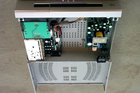
NU2V-2500
Oct 31, 2000Digital Satellite Receiver
Equipment Class
CYY - Communications Receiver used w/Pt 15 TransmitterNU2HFP-901-N
Apr 01, 1998CXX - Communications Rcvr for use w/ licensed Tx and CBs
Equipment Class
CXX - Communications Rcvr for use w/ licensed Tx and CBs