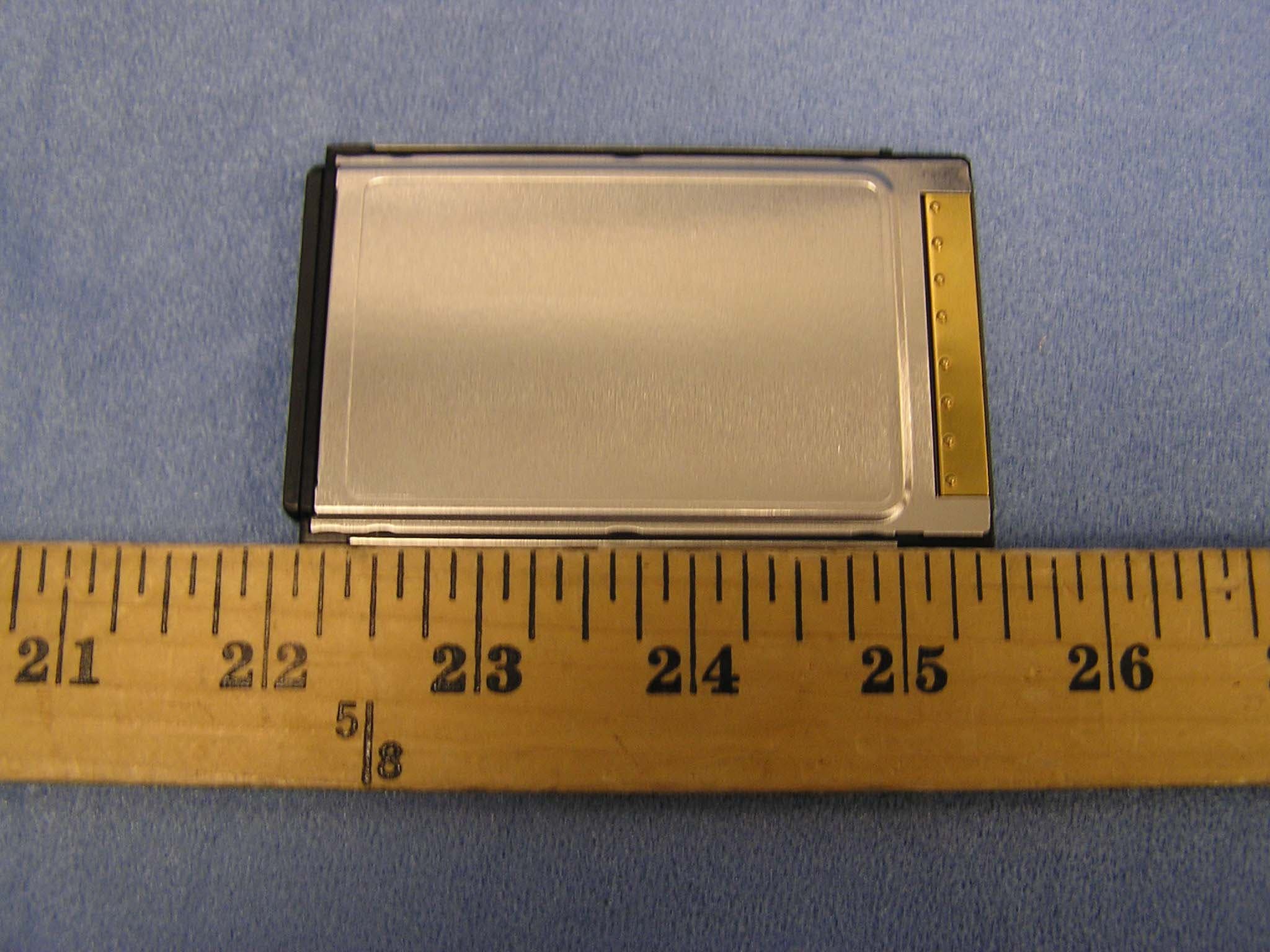
NUSTMW885A-22.4GHz Wireless LAN Card
Toko Inc
Click to zoom
Application Details
- Equipment Class
- DSS - Part 15 Spread Spectrum Transmitter
- Date of Grant
- Feb 05, 2001
- Application Purpose
- Original Equipment
- Date of Application
- Nov 20, 2000
- Equipment Note
- 2.4GHz Wireless LAN Card
- Frequency Range
- 2412.00000000 - 2462.00000000
- Company
- Toko Inc
- Country
- Japan
Documents & Files
Document Text
Text extracted from the exhibit documents filed with the FCC. Open a document above to read the original.
Cover Letter(s)
January 31, 2001 Federal Communications Commission Equipment Approval Services 7435 Oakland Mills Road Columbia, MD 21046 Attn: Ms. Steve Dayhoff SUBJECT:Toko Inc. FCC ID: NUSTMW885A-2 731 Confirmation No.: EA99336 Correspondence Reference No.: 17592 Request for Tech. Info.: 01/02/01 Dear Steve: Transmitted herewith, on behalf of Toko Inc., Ltd., is an amendment provided by IPS Corporation in response to the request for technical information dated January 01, 2001. 1. Please find attached the schematic diagrams 2. Please find attached the Technical description of antenna including dimensions, antenna design type, and isotropic gain. 3. Please find attached the Processing Gain Test Data with the description of the test setup. 4. Please find attached data that shows the average level radiation data for harmonic emissions. 5. Please find attached the revise RF Warning Statement. We trust this information is sufficient to re-issue the grant ASAP. If you have any further questions, please do not hesitate to contact us. cc:Toko Inc.
Operational Description
Peak Point 297° 89.6dBuV/m Peak Point 297° 89.6dBuV/m Peak Point 275° 91.6dBuV/m Peak Point 117° 88.2dBuV/m ANTENNA 90° 0° 180° 270° 3m
Operational Description
15.247 (e)Description of the test setup for the Processing Gain Test Data tables Measurement using the CW jamming margin method GP= (S/N) o + Mj + Lsys Where: (S/N)o = Signal to noise ratio Mj = J/S ratio Lsys = System losses Requirement : The processing gain shall be at least 10 dB Measurement Procedure 1. Test Configuration NOTE PC Toshiba DynaBook2520 Anritsu MG3633A Signal Generator NOTE PC IBM 390 Measurement Point at RF level. HP STEP ATTN 8494B 11dB (1dBsetps) HP STEP ATTN 8496B 110dB (10dBsetps) TMW885A-2 Anritsu ML2437A Power Meter Receiver TMW885A-2 S/N00003 (EUT) Transmitter ANRITSU K240B 2. Software The application of LanEval manufactured by INTERSIL shall be utilized for packet error rate (PER) measurement. Note: Packet error rate (PER) is same as Bit error rate (BER). 3.Measurement procedure 1. The transmitter (TMW885A-2) shall be kept continuously transmitted. STEP ATTN shall be adjusted to –50dBm for measurement value of power meter. This level is the output value of transmitter in measurement. 2. Signal Generator (SG) for CW Jammer shall be set to CH1 (2412MHz) and non-modulation and output ON, after the transmitter output OFF. SG output level shall be adjusted to –58.4dBm for measurement value of power meter. This level (–58.4dBm) is the reference level of minimum J/S, 10dB process gain. 3. CW Jammer is switched OFF, transmitter is ON in transmission conditions, and then packet error shall be measured with the receiver. It shall be confirmed that PER is error-free. 4. CW Jammer is switched ON at reference level and it shall be confirmed that PER is under 8%. 5. CW Jammer shall be adjusted to PER 8% and it shall be confirmed that the J/S is above –8.4dB to record. 6. 4 and 5 shall be repeated for measurement at 50KHz step in receiver transit range of 8.5MHz. 7. Measurement of 1 to 6 shall be performed in CH6 (2437MHz) and CH11 (2463MHz) as like as above. In case that some points are over PER 8% at step 4, it is acceptable if the number is under 20% of all measurement points. (The data of worst 20% must be excluded from the data of all measurement points to evaluate.) 4. Calculation for each channel CH1 (2412MHz) Across the Pass Band : 2403.52420.5 MHz (offset Frequency f = 8500 KHz) Worst J/S data point = -8.1 at offset Frequency f = -1550 KHz (2410.45 MHz) Discarding the worst 20% of the J/S data point. -8.10.8 = -6.48 The lowest remaining J/S ratio = -6.4 (S/N)o = 16.4 , Lsys = 2.0 12 (dB) = 16.4 + (-6.4) + 2.0 CH2 (2437MHz) Across the Pass Band : 2428.52445.5 MHz (offset Frequency f = 8500 KHz) Worst J/S data point = -8.1 at offset Frequency f = -1550 KHz (2435.45 MHz) Discarding the worst 20% of the J/S data point. -8.10.8 = -6.48 The lowest remaining J/S ratio = -6.4 (S/N)o = 16.4 , Lsys = 2.0 12 (dB) = 16.4 + (-6.4) + 2.0 CH3 (2462MHz) Across the Pass Band : 2453.52470.5 MHz (offset Frequency f = 8500 KHz) Worst J/S data point = -7.9 at offset Frequency f = -1550 KHz (2460.45 MHz) Discarding the worst 20% of the J/S data point. -7.90.8 = -6.32 The lowest remaining J/S ratio = -6.3 (S/N)o = 16.4 , Lsys = 2.0 12.1 (dB) = 16.4 + (-6.3) + 2.0
RF Exposure Info
Page 2 of 4 1. FCC Compliance Statement This device complies with Part 15 of the FCC Rules. Operation is subject to following two conditions: (1) this device may not cause harmful interference. and (2) this device must accept any interference received, including interference that may cause undesired operation. This equipment has been tested and found to comply with the limits for a Class B Personal Computer and Peripheral, pursuant to Part 15 of the FCC Rules. These limits are designed to provide reasonable protection against harmful interference in a residential installation. This equipment generates, uses and can radiate radio frequency energy and, if not installed and used in accordance with the instructions, may cause harmful interference to radio communications. However, there is no guarantee that interference will not occur in a particular installation. If this equipment does cause harmful interference to radio or television reception, which can be determined by turning the equipment off and on, the user is encouraged to try to correct the interference by one or more of the following measures: - Reorient or relocate the receiving antenna. - Increase the separation between the equipment and receiver. -Connect the equipment into an outlet on a circuit different from that to which the receiver is connected. - Consult the dealer or an experienced radio/TV technician for help. This equipment has been tested to comply with the limits for a Class B personal computer and peripheral, pursuant to Subpart B of Part 15 of FCC Rules. Only peripherals (computer input/output devices, terminals, printers, etc.) certified (DoC) or verified to comply with the Class B limits may be attached to this equipment. Operation with non-certified (DoC) or non-verified personal computer and/or peripherals is likely to result in interference to radio and TV reception. The connection of a unshielded equipment interface cable to this equipment will invalidate the FCC Certification of this device and may cause interference levels which exceed the limits established by the FCC for this equipment. You are cautioned that changes or modifications not expressly approved by the party responsible for compliance could void your authority to operate the equipment. 2. CAUTION Exposure to Radio Frequency radiation Antenna shall be mounted in such a manner to minimize the potential for human contact during normal operation. The antenna should allow 20cm clearance distance from antenna, to meet RF Exposure requirements for a mobile device. This card is designed to operate with a supply voltage of 3.3V in laptop computers supporting the dual 3V/5V PCMCIA standard. Permanent damage may occur if operated on 5V.
Test Report
IPS Corp. Page 1 of 39 MEASUREMENT / TECHNICAL REPORT for Certification Applicant: TOKO INC. Gomigaya-18, Tsurugashima-shi, Saitama-ken 350-2281 Japan, Kind of Equipment: Intentional Radiator 2.4GHz Wireless LAN Card FCC ID: NUSTMW885A-2 Model Number: TMW885A-2 Trade Name: TOKO Standard: 47 CFR Part 15 Subpart C Not authorized pursuant to the transition provisions in Section 15.37 Date Received: 09/27/2000 Date Tested: 09/27/2000-10/02/2000 Date Report Issued: 10/10/2000 Report Number: EMC00X03 Signature on the cover letter. IPS Corporation 1878-1 Harumiya Ono Tatsuno-machi, Kamiina-gun, Nagano-ken, 399-0601, Japan. Phone:+81-266-44-5200 Fax :+81-266-44-5300 C.M The measurements covered by this document have been performed in accordance with NVLAP requirements which include the requirements of ISO/IEC Guide 25:1990 and are traceable to national or international standards of measurement. This report summarizes the result of a single investigation and test result relate only to tested sample performed on the described test object. This test report must not be used by the client to claim product endorsement by NVLAP or agency of the U.S. Government. The report shall not be reproduced except in full without the written approval of the IPS Corporation. We hereby certify that no party to the applications authorized hereunder is subject to a denial of benefits, including FCC benefits, pursuant to Section 5301 of the Anti-Drug Abuse Act of 1988, 21 U.S.C 853(a). NVLAP LAB CODE:200012-0 Report No.:EMC00X03 FCC ID:NUSTMW885A-2 IPS Corp. Page 2 of 39 <Table of Contents> <Page> 1 GENERAL INFORMATION............................................4 1.1 Product Description...............................................4 1.2 Summary of Test and Inspection Result................................5 1.3 Related Submittal(s)/Grant(s)........................................5 1.4 Tested Systems Details.............................................6 1.5 Test Methodology.................................................9 1.6 Test Facility.....................................................9 2 PRODUCT LABELING...............................................10 Figure 2.1 FCC ID Label.............................................10 Figure 2.2 Location of Label on EUT....................................10 3 SYSTEM TEST CONFIGURATION.....................................11 3.1 Justification....................................................11 3.2 EUT Exercise Software............................................11 3.3 Special Accessories...............................................12 3.4 Equipment Modifications..........................................12 3.5 Configuration of Tested System.....................................13 Figure 3.1 Configuration of Tested System................................13 4 BLOCK DIAGRAM (S) OF FCC ID: NUSTMW885A-2.......................14 4.1 Block Diagram Description.........................................14 Figure 4.1 Block Diagram of FCC ID: NUSTMW885A-2......................14 5 ANTENNA REQUIREMENT..........................................15 6 CONDUCTED EMISSION TEST.......................................16 6.1 Test Setup.....................................................16 6.2 Instrumentation.................................................17 6.3 Measurement Data...............................................19 6.4 CONDUCTED MEASUREMENT PHOTOS............................20 Figure 6.1 Configuration photo of Conducted Measurement...................20 7 RADIATED EMISSION TEST.........................................21 7.1 Test Setup.....................................................21 7.2 Instrumentation.................................................22 7.3 Field Strength Calculation.........................................26 7.4 Measurement Data...............................................27 7.5 RADIATED MEASUREMENT PHOTOS..............................29 Figure 7.1 Configuration photo of Radiated Measurement (9kHz – 30MHz).......29 Figure 7.2 Configuration photo of Radiated Measurement (30MHz – 1GHz).......30 Figure 7.3 Configuration photo of Radiated Measurement (1GHz – 25GHz).......30 <Table of Contents> <Page> 8 OPERATION WITHIN THE BANDS 2400-2483.5 (15.247)....................31 8.1 15.247 (a) (2)...................................................31 Report No.:EMC00X03 FCC ID:NUSTMW885A-2 IPS Corp. Page 3 of 39 8.2 15.247 (b) (1)...................................................31 8.3 15.247 (b) (3)...................................................31 8.4 15.247 (b) (3) (iii)................................................31 8.5 15.247 (b) (4), 1.1307 (b) (1), 1.1310 Table 1B...........................31 8.6 15.247 (c)......................................................31 8.7 15.247 (d)......................................................31 8.8 15.247 (e)......................................................31 9 APPLICANT AND MANUFACTURER INFORMATION.....................38 9.1 Engineering Statement............................................38 10 PHOTOS OF TESTED EUT..........................................39 Figure 1 Inner View Component Side of the Main Board......................39 Figure 2 Inner View Foil Side of the Main Board............................39 Figure 3 Front View.................................................39 Figure 4 Front View.................................................39 Report No.:EMC00X03 FCC ID:NUSTMW885A-2 IPS Corp. Page 4 of 39 1 GENERAL INFORMATION The test report includes the out of scope of the NVLAP and JAB accreditation . The test results and the measurements made in this test report of following section are out of scope of NVLAP and JAB accreditation. 1.1307 (b)(1), 1.1310 Table 1B 15.247 (a)-(2), (b)-(1), (b)-(3), (b)-(3)-(iii), (b)-(4), (c), (d), (e) 1.1 Product Description The TOKO INC 2.4GHz Wireless LAN Card, Model: TMW885A-2, FCC ID: NUSTMW885A-2 (referred to as the EUT in this report) is operated within the bands 2400 – 2483…
Text truncated - open the document above for the full version.
Contact Information
Applicant
Go Ishii(Q.C Manager)
81 49 279-1623Fax: 81 49 279-1891
Technical Contact
PCTEST Engineering Laboratory, Inc.Randy Ortanez
[email protected]410-290-6652
6660-B Dobbin Road · Columbia, Maryland · United States
Non-Technical Contact
PCTEST Engineering Laboratory, Inc.Randy Ortanez
[email protected]410-290-6652
Test Firm
PCTEST Engineering Laboratory, Inc.Randy Ortanez
Technical Specifications
| # | Rule Parts | Frequency Range | Power Output |
|---|---|---|---|
| 1 | 15C | 2.41 GHz - 2.46 GHz | 17.00 mW |
Other Applications from Toko Inc
NUSTMW1059
May 17, 2004802.11 b/g Wireless LAN Card
Equipment Class
DTS - Digital Transmission System
NUSTMW1052
Aug 06, 20032.4G WirelessLAN Mini -PCI Card
Equipment Class
DTS - Digital Transmission System
NUSTMW1008
Jan 30, 20032.4GHz Wireless LAN Card
Equipment Class
DSS - Part 15 Spread Spectrum Transmitter
NUSTMW1003
Feb 03, 2002Wireless Access Point
Equipment Class
DSS - Part 15 Spread Spectrum TransmitterNUSCFO-SS10
Dec 09, 1998WLAN
Equipment Class
DSS - Part 15 Spread Spectrum Transmitter