NVA010164-004APoint of Sale Device
Equinox Payments LLC
Click to zoom
Application Details
- Equipment Class
- TNB - Licensed Non-Broadcast Station Transmitter
- Date of Grant
- May 10, 2000
- Application Purpose
- Original Equipment
- Date of Application
- Feb 10, 2000
- Equipment Note
- Point of Sale Device
- Frequency Range
- 896.00000000 - 902.00000000
- Company
- Equinox Payments LLC
- Country
- United States
Documents & Files
Document Text
Text extracted from the exhibit documents filed with the FCC. Open a document above to read the original.
Users Manual
January 2000 APREL Project No.: HYPB-SMARTICE-Mobitex-3366 Consulting * Research * Training * Certification Testing Since 1981 Exhibit 9 SmartICE/MOBITEX Point of Sale Device Hypercom FCC ID: NVA010164-004A User’s Manual SmartICE Hardware and Installation Manual Version 1.0 January 26, 2000 draft Corporate Telephone 602.504.5000 Corporate Fax 602.866.5380 Corporate Website www.hypercom.com Copyright 2000 by Hypercom Corporation. Produced in the United States of America. Hypercom Corporation 2851 West Kathleen Road Phoenix, Arizona 85053 USA Hypercom Corporation 2000. All rights reserved. Hypercom and the Hyprcom logo are registered trademarks of Hypercom Corporation. Hypercom has attempted throughout this publication to distinguish proprietary trademarks from descriptive terms by following the capitalization style used by the manufacturer. This document is proprietary to Hypercom Corporation and is intended solely for use by Hypercom customers. This publication may not be reproduced or distributed for any purpose without the written permission of Hypercom Corporation. NOTICE Hypercom Corporation reserves the right to make changes to the publication at any time and without notice. The information furnished in this publication by Hypercom Corporation is believed to be accurate and reliable; however, Hypercom Corporation assumes no responsibility for its use. Any error in identifying or reflecting any proprietary marks or notices is inadvertent and unintentional. This document applies to the SmartICE Series Terminals. FCC PART 15 REQUIREMENTS NOTICE ß · This device must not be installed on coin-operated telephone lines or party lines. · This device (equipment) complies with the requirements in Part 15 of FCC Rules for a Class B computing device. Operation of this device (equipment) is subject to the following two conditions: - This device (equipment) may not cause harmful interference, and - This device must accept any interference received, including interference that may cause undesired operation. · If this device (equipment) is used in a residential area, it may cause unacceptable interference to radio and TV reception requiring the operator to take whatever steps necessary to correct the interference. · Repair work on this device (equipment) must by done by Hypercom Corporation or an authorized repair station. 940264-001Hypercom Corporationv Table of Contents Introduction Document Organization. . . . . . . . . . . . . . . . . . . . . . . . . . . . . . . . . . . . . . . . . . . . . . . . . . . . . . . . . . . . . . . . . . . . . xiii Document Conventions . . . . . . . . . . . . . . . . . . . . . . . . . . . . . . . . . . . . . . . . . . . . . . . . . . . . . . . . . . . . . . . . . . . . . . . . . . xiii Notes. . . . . . . . . . . . . . . . . . . . . . . . . . . . . . . . . . . . . . . . . . . . . . . . . . . . . . . . . . . . . . . . . . . . . . . . . . . . . . . . xiii Component Names. . . . . . . . . . . . . . . . . . . . . . . . . . . . . . . . . . . . . . . . . . . . . . . . . . . . . . . . . . . . . . . . . . . . . . . . . . . . . xiii Procedures. . . . . . . . . . . . . . . . . . . . . . . . . . . . . . . . . . . . . . . . . . . . . . . . . . . . . . . . . . . . . . . . . . . . . . . . . . . .xiv Warning and Caution Messages . . . . . . . . . . . . . . . . . . . . . . . . . . . . . . . . . . . . . . . . . . . . . . . . . . . . . . . . . . . . . . . . . . xiv Chapter 1 Equipment Information Terminal Information. . . . . . . . . . . . . . . . . . . . . . . . . . . . . . . . . . . . . . . . . . . . . . . . . . . . . . . . . . . . . . . . . . . . . . . .1-1 Features. . . . . . . . . . . . . . . . . . . . . . . . . . . . . . . . . . . . . . . . . . . . . . . . . . . . . . . . . . . . . . . . . . . . . . . . . . . . . . . . . . . 1-2 Terminal Connection Ports . . . . . . . . . . . . . . . . . . . . . . . . . . . . . . . . . . . . . . . . . . . . . . . . . . . . . . . . . . . . . . . . . . . . 1-3 LAN Port . . . . . . . . . . . . . . . . . . . . . . . . . . . . . . . . . . . . . . . . . . . . . . . . . . . . . . . . . . . . . . . . . . . . . . . . . . . . 1-3 PIN Pad Port . . . . . . . . . . . . . . . . . . . . . . . . . . . . . . . . . . . . . . . . . . . . . . . . . . . . . . . . . . . . . . . . . . . . . . . . . 1-3 Power Port. . . . . . . . . . . . . . . . . . . . . . . . . . . . . . . . . . . . . . . . . . . . . . . . . . . . . . . . . . . . . . . . . . . . . . . . . . . . 1-3 Contrast Control Dial . . . . . . . . . . . . . . . . . . . . . . . . . . . . . . . . . . . . . . . . . . . . . . . . . . . . . . . . . . . . . . . . . . . . . . . . . . . . 1-3 Terminal Modem. . . . . . . . . . . . . . . . . . . . . . . . . . . . . . . . . . . . . . . . . . . . . . . . . . . . . . . . . . . . . . . . . . . . . . . . . . 1-3 Terminal Radio. . . . . . . . . . . . . . . . . . . . . . . . . . . . . . . . . . . . . . . . . . . . . . . . . . . . . . . . . . . . . . . . . . . . . . . . . . . . . 1-3 Terminal Power Adaptors. . . . . . . . . . . . . . . . . . . . . . . . . . . . . . . . . . . . . . . . . . . . . . . . . . . . . . . . . . . . . . . . . . . 1-3 Transactions and Functions . . . . . . . . . . . . . . . . . . . . . . . . . . . . . . . . . . . . . . . . . . . . . . . . . . . . . . . . . . . . . . . . . . . . 1-4 Terminal Initialization . . . . . . . . . . . . . . . . . . . . . . . . . . . . . . . . . . . . . . . . . . . . . . . . . . . . . . . . . . . . . . . . . . .1-4 Terminal Diagnostics . . . . . . . . . . . . . . . . . . . . . . . . . . . . . . . . . . . . . . . . . . . . . . . . . . . . . . . . . . . . . . . . . . .1-4 Application Program Changes . . . . . . . . . . . . . . . . . . . . . . . . . . . . . . . . . . . . . . . . . . . . . . . . . . . . . . . . . . . . . . . . . . .1-4 Financial Integrity . . . . . . . . . . . . . . . . . . . . . . . . . . . . . . . . . . . . . . . . . . . . . . . . . . . . . . . . . . . . . . . . . . . . . . . . . 1-5 Fast Response Times . . . . . . . . …
Text truncated - open the document above for the full version.
Users Manual
ICE 4000 Hardware and Installation Manual Version 1.0 May 8, 2000 Corporate Telephone: 602.504.5000 Corporate Fax: 602.866.5380 Corporate Web Site: www.hypercom.com Copyright 2000 by Hypercom Corporation. Produced in the United States of America. Hypercom Corporation 2851 West Kathleen Road Phoenix, Arizona 85053 USA Hypercom Corporation 2000. All rights reserved. Hypercom and the Hyprcom logo are registered trademarks of Hypercom Corporation. Hypercom has attempted throughout this publication to distinguish proprietary trademarks from descriptive terms by following the capitalization style used by the manufacturer. This document is proprietary to Hypercom Corporation and is intended solely for use by Hypercom customers. This publication may not be reproduced or distributed for any purpose without the written permission of Hypercom Corporation. NOTICE Hypercom Corporation reserves the right to make changes to the publication at any time and without notice. The information furnished in this publication by Hypercom Corporation is believed to be accurate and reliable; however, Hypercom Corporation assumes no responsibility for its use. Any error in identifying or reflecting any proprietary marks or notices is inadvertent and unintentional. This document applies to the Hypercom ICE 4000 terminal. n This device must not be installed on coin-operated telephone lines or party lines. n This device (equipment) complies with the requirements in Part 15 of FCC Rules for a Class A computing device. Operation of this device (equipment) is subject to the following two conditions: –This device (equipment) may not cause harmful interference, and –This device must accept any interference received, including interference that may cause undesired operation. n If this device (equipment) is used in a residential area, it may cause unacceptable interference to radio and TV reception requiring the operator to take whatever steps necessary to correct the interference. n Repair work on this device (equipment) must by done by Hypercom Corporation or an authorized repair station. This equipment has been tested and found to comply with the limits for a class B digital devise, pursuant to Part 15 of the FCC Rules. These limits are designed to provide reasonable protection against harmful interference in a residential installation. This equipment generates, uses, and can radiate radio frequency energy and if not installed and used in accordance with the instructions, may cause harmful interference to radio communications. However, there is no guarantee that interference will not occur in a particular installation. If this equipment does cause harmful interference to radio and or television reception, which can be determined by turning the equipment off and on, the user is encouraged to attempt to correct the interference by one or more of the following measures: n Reorient or relocate the receiving antenna n Increase the separation between the equipment and the receiver n Connect the equipment into an electrical outlet on a circuit different from that to which the receiver is connected n Consult the dealer or an experience radio or television technician for assistance This equipment has been certified to comply within the limits for a Class B computing devise, pursuant to FCC Rules. In order to maintain compliance with FCC regulations, shielded cables must be used with this equipment. Operation with non-approved equipment or unsheilded cable is likely to result in radio and or television interference. The user is cautioned that changes and modifications made to this equipment without the expressed approval of the manufacturer, could void the user’s authority to operate this equipment. WARNING: To comply with FCC RF exposure requirements, the CDPD or Mobitex units must be operated with a minimum separation distance of 3 cm (1-1/8 inches) between its antenna and a person’s body. The user’s hand should not be placed next to the antenna or at locations on the unit where the antenna is connected. A minimum separation distance of 1.5 cm is needed to ensure compliance with FCC RF exposure limits for the hand. FCC PART 15 REQUIREMENTS NOTICE 940265-001Hypercom Corporationv Table of Contents List of Figures Introduction Document Organization. . . . . . . . . . . . . . . . . . . . . . . . . . . . . . . . . . . . . . . . . . . . . . . . . . . . . . . . . . . . . . . . . . . . . xiii Document Conventions . . . . . . . . . . . . . . . . . . . . . . . . . . . . . . . . . . . . . . . . . . . . . . . . . . . . . . . . . . . . . . . . . . . . . xiii Chapter 1 Equipment Information Terminal Information. . . . . . . . . . . . . . . . . . . . . . . . . . . . . . . . . . . . . . . . . . . . . . . . . . . . . . . . . . . . . . . . . . . . . . . .1-1 Features. . . . . . . . . . . . . . . . . . . . . . . . . . . . . . . . . . . . . . . . . . . . . . . . . . . . . . . . . . . . . . . . . . . . . . . . . . . . . . . . . . . 1-2 ICE 4000 Hardware Features . . . . . . . . . . . . . . . . . . . . . . . . . . . . . . . . . . . . . . . . . . . . . . . . . . . . . . . . . . . . . . . . . . . . 1-3 Transactions and Functions . . . . . . . . . . . . . . . . . . . . . . . . . . . . . . . . . . . . . . . . . . . . . . . . . . . . . . . . . . . . . . . . . . . . 1-4 Terminal Initialization . . . . . . . . . . . . . . . . . . . . . . . . . . . . . . . . . . . . . . . . . . . . . . . . . . . . . . . . . . . . . . . . . . .1-4 Terminal Diagnostics . . . . . . . . . . . . . . . . . . . . . . . . . . . . . . . . . . . . . . . . . . . . . . . . . . . . . . . . . . . . . . . . . . .1-4 Application Program Changes . . . . . . . . . . . . . . . . . . . . . . . . . . . . . . . . . . . . . . . . . . . . . . . . . . . . . . . . . . . . . . . . . . .1-4 Financial Integrity . . . . . . . . . . . . . . . . . . . . . . . . . . . . . . . . . . . . . . . . . . . . . . . . . . . . . . . . . . . . . . . . . . . . . . . . . 1-5 Fast Response Times . . . . . . . . . . . . . …
Text truncated - open the document above for the full version.
Attestation Statements
January 2000 APREL Project No.: HYPB-SMARTICE-Mobitex-3366 Consulting * Research * Training * Certification Testing Since 1981 Exhibit 1 SmartICE/MOBITEX Point of Sale Device Hypercom FCC ID: NVA010164-004A Authorization letter Letter requesting Confidentiality Letter from Research in Motion authorizing to use Mobitex modem in Hypercom product
Attestation Statements
January 2000 APREL Project No.: HYPB-SMARTICE-Mobitex-3366 Consulting * Research * Training * Certification Testing Since 1981 Exhibit 11 SmartICE/MOBITEX Point of Sale Device Hypercom FCC ID: NVA010164-004A FCC Part 15, Subpart B DoC letter
Attestation Statements
January 2000 APREL Project No.: HYPB-SMARTICE-Mobitex-3366 Consulting * Research * Training * Certification Testing Since 1981 Exhibit 1 SmartICE/MOBITEX Point of Sale Device Hypercom FCC ID: NVA010164-004A Authorization letter Letter requesting Confidentiality Letter from Research in Motion authorizing to use Mobitex modem in Hypercom product
Attestation Statements
January 2000 APREL Project No.: HYPB-SMARTICE-Mobitex-3366 Consulting * Research * Training * Certification Testing Since 1981 Exhibit 11 SmartICE/MOBITEX Point of Sale Device Hypercom FCC ID: NVA010164-004A FCC Part 15, Subpart B DoC letter
Cover Letter(s)
January 2000 APREL Project No.: HYPB-SMARTICE-Mobitex-3366 Consulting * Research * Training * Certification Testing Since 1981 Table of Contents Point of Sale Device SmartICE with a Research in Motion R902M-2-0 Transmitter, Mobitex FCC ID: NVA010164-004A Hypercom C C O O V V E E R R L L E E T T T T E E R R Exhibit 1: a. Authorization Letter and, b. Request for confidentiality c. Letter from Research in Motion authorizing to use Mobitex modem in Hypercom product Exhibit 2:Engineering Report (Includes Test Set-up Photographs) Exhibit 3: Technical Descriptions and Tune-up Procedure Exhibit 4: FCC ID Label Exhibit 5:Photographs of the Equipment Internal and External Exhibit 6: Block Diagram (Confidential) Exhibit 7: Schematic Diagram (Confidential) Exhibit 8:Parts List (Confidential) Exhibit 9:User’s Manual Exhibit 10:SAR Report (Includes Test Set-up Photographs) Exhibit 11: FCC Part 15, Subpart B, DoC letter
Cover Letter(s)
January 2000 APREL Project No.: HYPB-SMARTICE-Mobitex-3366 Consulting * Research * Training * Certification Testing Since 1981 Table of Contents Point of Sale Device SmartICE with a Research in Motion R902M-2-0 Transmitter, Mobitex FCC ID: NVA010164-004A Hypercom C C O O V V E E R R L L E E T T T T E E R R Exhibit 1: a. Authorization Letter and, b. Request for confidentiality c. Letter from Research in Motion authorizing to use Mobitex modem in Hypercom product Exhibit 2:Engineering Report (Includes Test Set-up Photographs) Exhibit 3: Technical Descriptions and Tune-up Procedure Exhibit 4: FCC ID Label Exhibit 5:Photographs of the Equipment Internal and External Exhibit 6: Block Diagram (Confidential) Exhibit 7: Schematic Diagram (Confidential) Exhibit 8:Parts List (Confidential) Exhibit 9:User’s Manual Exhibit 10:SAR Report (Includes Test Set-up Photographs) Exhibit 11: FCC Part 15, Subpart B, DoC letter
External Photos
January 2000 APREL Project No.: HYPB-SMARTICE-Mobitex-3366 Consulting * Research * Training * Certification Testing Since 1981 Exhibit 5 SmartICE/MOBITEX Point of Sale Terminal Hypercom FCC ID: NVA010164-004A Photographs of the Equipment Internal External Hypercom Point of Sale Device, SmartICE with RIM R902M-2-0 Transmitter, Mobitex:: Front Hypercom Point of Sale Device, SmartICE with RIM R902M-2-0 Transmitter, Mobitex: Front open Hypercom Point of Sale Device, SmartICE with RIM R902M-2-0 Transmitter, Mobitex: Front open Hypercom Point of Sale Device, SmartICE with RIM R902M-2-0 Transmitter, Mobitex:Front open, detail, under screen Hypercom Point of Sale Device, SmartICE with RIM R902M-2-0 Transmitter, Mobitex: Front open, detail, back of screen Hypercom Point of Sale Device, SmartICE with RIM R902M-2-0 Transmitter, Mobitex:Back, battery compartment Hypercom Point of Sale Device, SmartICE with RIM R902M-2-0 Transmitter, Mobitex:Back, battery Hypercom Point of Sale Device, SmartICE with RIM R902M-2-0 Transmitter, Mobitex:, Back open Hypercom Point of Sale Device, SmartICE with RIM R902M-2-0 Transmitter, Mobitex:Back open, detail, transmitter Hypercom Point of Sale Device, SmartICE with RIM R902M-2-0 Transmitter, Mobitex:Back open, board connected to transmitter Hypercom Point of Sale Device, SmartICE with RIM R902M-2-0 Transmitter, Mobitex:Back open, board connected to transmitter detail
External Photos
January 2000 APREL Project No.: HYPB-SMARTICE-Mobitex-3366 Consulting * Research * Training * Certification Testing Since 1981 Exhibit 5 SmartICE/MOBITEX Point of Sale Terminal Hypercom FCC ID: NVA010164-004A Photographs of the Equipment Internal External Hypercom Point of Sale Device, SmartICE with RIM R902M-2-0 Transmitter, Mobitex:: Front Hypercom Point of Sale Device, SmartICE with RIM R902M-2-0 Transmitter, Mobitex: Front open Hypercom Point of Sale Device, SmartICE with RIM R902M-2-0 Transmitter, Mobitex: Front open Hypercom Point of Sale Device, SmartICE with RIM R902M-2-0 Transmitter, Mobitex:Front open, detail, under screen Hypercom Point of Sale Device, SmartICE with RIM R902M-2-0 Transmitter, Mobitex: Front open, detail, back of screen Hypercom Point of Sale Device, SmartICE with RIM R902M-2-0 Transmitter, Mobitex:Back, battery compartment Hypercom Point of Sale Device, SmartICE with RIM R902M-2-0 Transmitter, Mobitex:Back, battery Hypercom Point of Sale Device, SmartICE with RIM R902M-2-0 Transmitter, Mobitex:, Back open Hypercom Point of Sale Device, SmartICE with RIM R902M-2-0 Transmitter, Mobitex:Back open, detail, transmitter Hypercom Point of Sale Device, SmartICE with RIM R902M-2-0 Transmitter, Mobitex:Back open, board connected to transmitter Hypercom Point of Sale Device, SmartICE with RIM R902M-2-0 Transmitter, Mobitex:Back open, board connected to transmitter detail
ID Label/Location Info
January 2000 APREL Project No.: HYPB-SMARTICE-Mobitex-3366 Consulting * Research * Training * Certification Testing Since 1981 Exhibit 4 SmartICE/MOBITEX Point of Sale Device Hypercom FCC ID: NVA010164-004A FCC ID Label
ID Label/Location Info
January 2000 APREL Project No.: HYPB-SMARTICE-Mobitex-3366 Consulting * Research * Training * Certification Testing Since 1981 Exhibit 4 SmartICE/MOBITEX Point of Sale Device Hypercom FCC ID: NVA010164-004A FCC ID Label
Operational Description
January 2000 APREL Project No.: HYPB-SMARTICE-Mobitex-3366 Consulting * Research * Training * Certification Testing Since 1981 Exhibit 3 SmartICE/MOBITEX Point of Sale Device Hypercom FCC ID: NVA010164-004A Technical Descriptions and Tune-up Procedure Ref: FCC Parts 2 paragraph 2.983(d) TECHNICAL DESCRIPTION OF THE EQUIPMENT Ref.: FCC Part 2 paragraph 2.983(d) Hypercom Point of Sale Device SmartICE With a Research in Motion R902M-2-0 Transmitter, Mobitex Tune-up Procedure at Nominal Operating Power: Limiting Power: The unit integrates the RIM Mobitex module that complies with part 90 under FCCID L6AR902M-2-0 which will not allow us to exceed the max allowable limit. Circuitry and Devices for Determining and Stabilizing Frequency: Frequency Stabilization: The unit integrates the RIM Mobitex module that complies with part 22 under FCCID L6AR902M-2-0 which has demonstrated a stability of 1.5 PPM. Suppression of Spurious Radiation: Spurious and harmonic suppression is achieved by proper board layout, power distribution among ground planes and good filtering. We have demonstrated continuous compliance in our factory. Limiting Modulation: The unit integrates the RIM Mobitex module which complies with part 90 under FCCID L6AR902M-2-0 which will not allow us to alter modulation from the GMSK. Hypercom Smart ICE Main Power Supply: The main power supply for the Smart ICE consists of an LTC1143 controller IC along with bipolar drivers, FET switches and a Schottky commutation diode. The chip is able to control two (2) buck mode regulators at different output voltages. Both regulators are similar except for the voltage setpoint, only one circuit will be described. An on chip linear regulator supplies chip power with an input voltage of 6 – 16VDC. The regulator senses voltage at the output of the regulator, and current being fed to the load. The voltage is controlled by pulse width modulation of the drive pulses in a constant off time configuration so the frequency of operation varies around 150 kHz. The drive pulses are current boosted by the driver transistors and applied to the gate of a p-channel FET switch. The drain of the FET is tied to the commutating diode and the energy storage inductor. The output of the inductor is tied to a current sense resistor, then to the filter capacitor and out to the powered circuitry. Battery Charger: The battery charger consists of a single chip charger IC (BQ2000) which runs as a current controlled buck mode regulator at a frequency of approximately 120 kHz. The width of the output pulses is controlled to give a constant charge current of 1/3 amp. Once the battery has reached approximately 90% charge the mode is changed to a burst mode holding a constant voltage and the battery is topped off to about 98-100% charge level. The charge can also be stopped by a timer built into the chip or by sensing the battery temperature via a thermistor built in to the battery pack. Magnetic Card Reader: The F/2F Read/Decode IC will recover clock and data signals from an F/2F data stream generated from a magnetic head. The IC will function for data rates from 150 to more than 12,000 bits per second. Display and Display Driver: The system display consists of a 160 x 160 pixel FSTN LCD module, driven by an Epson SED1335 graphic LCD controller IC. The 9.83 MHz system clock drives the SED1335. The LCD display is powered by an LT1303 DC/DC converter, which boosts the 5-volt system power up to 22 VDC. The DC/DC converter switches at approximately 150 kHz. The LCD display has an EL backlight. A DUREL D355A driver IC drives the backlight. It produces an AC voltage of approximately 75 Volts RMS at a frequency of approximately 220 Hz. Touchscreen Controller: The display’s touchscreen is controlled by a Burr Brown ADS7843. The ADS7843 runs from a 1.2 MHz clock. The ADS7843 samples the touch screen at a rate of 1000 points per second (500 X-Y pairs per second). System FPGA: The system FPGA is a Xilinx Spartan 10XL. It acts as glue logic for the system. It is connected to the 9.8 MHz system clock, which it divides down in to the 1.22 MHz touchscreen controller clock, and also produces the 1.2 kHz, 1.6 kHz, and 2.4kHz clocks to drive the piezo buzzer. System ASIC: The system ASIC performs memory and I/O decoding functions for the Z80 microcontroller. It protects the SRAM from being written to during power up and power down, and contains a 16-bit timer for the Z80’s operating system. It also contains registers that identify the amount of system memory and system clock frequency. It also performs serial to parallel conversion for one track of magnetic card data. System Processor and Memory: The main system processor is a Zilog Z84C15. It is a member of the Z80 family, and runs with a system clock of 9.83 MHz. It can access up to 1.5 MB of static RAM memory plus 128 KB of FLASH memory. RS232 / 485 Communications: The TTL level serial communication ports on the Z80 are converted to RS232 / RS485 levels with an LTC1387 Multiprotocol Tranceiver I.C. with on board charge pump. Mobitex Radio: This radio consists of a Research In Motion (RIM) OEM Radio Module 902M, manufactured by RIM to support the Mobitex standard. The module supports a serial interface of 3.0 Vdc with data rates up to 9600 baud. The transmitter delivers from 62mW to 2.0 W into the 50-ohm antenna port. The transmit frequency band is 896 – 902 Mhz and receive band is 935 to 941 Mhz. The main power supply requires 4.1 to 4.75 Vdc. The current usage of the module is apx .2 mA in sleep mode, 5.4 mA in standby mode, up to 57mA in receive mode, and up to 1.7 A one-second burst when required by the transmitter. The Antenna connection is 50 Ohm impedance. Printer: The system prints using a Panasonic EPLZ2050 thermal printer. The printer is controlled by a PIC16C74, which is driven by the 9.83 MHz system clock. The printer’s paper feed and cutter motors are driven by both Rohm BA6845 and Sanyo LB1836 stepper motor driver ICs, which are also…
Text truncated - open the document above for the full version.
Parts List/Tune Up Info
January 2000 APREL Project No.: HYPB-SMARTICE-Mobitex-3366 Consulting * Research * Training * Certification Testing Since 1981 Exhibit 3 SmartICE/MOBITEX Point of Sale Device Hypercom FCC ID: NVA010164-004A Technical Descriptions and Tune-up Procedure Ref: FCC Parts 2 paragraph 2.983(d) TECHNICAL DESCRIPTION OF THE EQUIPMENT Ref.: FCC Part 2 paragraph 2.983(d) Hypercom Point of Sale Device SmartICE With a Research in Motion R902M-2-0 Transmitter, Mobitex Tune-up Procedure at Nominal Operating Power: Limiting Power: The unit integrates the RIM Mobitex module that complies with part 90 under FCCID L6AR902M-2-0 which will not allow us to exceed the max allowable limit. Circuitry and Devices for Determining and Stabilizing Frequency: Frequency Stabilization: The unit integrates the RIM Mobitex module that complies with part 22 under FCCID L6AR902M-2-0 which has demonstrated a stability of 1.5 PPM. Suppression of Spurious Radiation: Spurious and harmonic suppression is achieved by proper board layout, power distribution among ground planes and good filtering. We have demonstrated continuous compliance in our factory. Limiting Modulation: The unit integrates the RIM Mobitex module which complies with part 90 under FCCID L6AR902M-2-0 which will not allow us to alter modulation from the GMSK. Hypercom Smart ICE Main Power Supply: The main power supply for the Smart ICE consists of an LTC1143 controller IC along with bipolar drivers, FET switches and a Schottky commutation diode. The chip is able to control two (2) buck mode regulators at different output voltages. Both regulators are similar except for the voltage setpoint, only one circuit will be described. An on chip linear regulator supplies chip power with an input voltage of 6 – 16VDC. The regulator senses voltage at the output of the regulator, and current being fed to the load. The voltage is controlled by pulse width modulation of the drive pulses in a constant off time configuration so the frequency of operation varies around 150 kHz. The drive pulses are current boosted by the driver transistors and applied to the gate of a p-channel FET switch. The drain of the FET is tied to the commutating diode and the energy storage inductor. The output of the inductor is tied to a current sense resistor, then to the filter capacitor and out to the powered circuitry. Battery Charger: The battery charger consists of a single chip charger IC (BQ2000) which runs as a current controlled buck mode regulator at a frequency of approximately 120 kHz. The width of the output pulses is controlled to give a constant charge current of 1/3 amp. Once the battery has reached approximately 90% charge the mode is changed to a burst mode holding a constant voltage and the battery is topped off to about 98-100% charge level. The charge can also be stopped by a timer built into the chip or by sensing the battery temperature via a thermistor built in to the battery pack. Magnetic Card Reader: The F/2F Read/Decode IC will recover clock and data signals from an F/2F data stream generated from a magnetic head. The IC will function for data rates from 150 to more than 12,000 bits per second. Display and Display Driver: The system display consists of a 160 x 160 pixel FSTN LCD module, driven by an Epson SED1335 graphic LCD controller IC. The 9.83 MHz system clock drives the SED1335. The LCD display is powered by an LT1303 DC/DC converter, which boosts the 5-volt system power up to 22 VDC. The DC/DC converter switches at approximately 150 kHz. The LCD display has an EL backlight. A DUREL D355A driver IC drives the backlight. It produces an AC voltage of approximately 75 Volts RMS at a frequency of approximately 220 Hz. Touchscreen Controller: The display’s touchscreen is controlled by a Burr Brown ADS7843. The ADS7843 runs from a 1.2 MHz clock. The ADS7843 samples the touch screen at a rate of 1000 points per second (500 X-Y pairs per second). System FPGA: The system FPGA is a Xilinx Spartan 10XL. It acts as glue logic for the system. It is connected to the 9.8 MHz system clock, which it divides down in to the 1.22 MHz touchscreen controller clock, and also produces the 1.2 kHz, 1.6 kHz, and 2.4kHz clocks to drive the piezo buzzer. System ASIC: The system ASIC performs memory and I/O decoding functions for the Z80 microcontroller. It protects the SRAM from being written to during power up and power down, and contains a 16-bit timer for the Z80’s operating system. It also contains registers that identify the amount of system memory and system clock frequency. It also performs serial to parallel conversion for one track of magnetic card data. System Processor and Memory: The main system processor is a Zilog Z84C15. It is a member of the Z80 family, and runs with a system clock of 9.83 MHz. It can access up to 1.5 MB of static RAM memory plus 128 KB of FLASH memory. RS232 / 485 Communications: The TTL level serial communication ports on the Z80 are converted to RS232 / RS485 levels with an LTC1387 Multiprotocol Tranceiver I.C. with on board charge pump. Mobitex Radio: This radio consists of a Research In Motion (RIM) OEM Radio Module 902M, manufactured by RIM to support the Mobitex standard. The module supports a serial interface of 3.0 Vdc with data rates up to 9600 baud. The transmitter delivers from 62mW to 2.0 W into the 50-ohm antenna port. The transmit frequency band is 896 – 902 Mhz and receive band is 935 to 941 Mhz. The main power supply requires 4.1 to 4.75 Vdc. The current usage of the module is apx .2 mA in sleep mode, 5.4 mA in standby mode, up to 57mA in receive mode, and up to 1.7 A one-second burst when required by the transmitter. The Antenna connection is 50 Ohm impedance. Printer: The …
Text truncated - open the document above for the full version.
Contact Information
Applicant
Clint Woodworth(Manager Regulatory Compliance)
Technical Contact
Hypercom CorporationBill Safieh
[email protected]602-504-5180
2851 West Kathleen Road · Phoenix, Arizona · United States
Non-Technical Contact
Hypercom CorporationAdelia Crowley
[email protected]602-504-5769
Test Firm
APREL LaboratoriesJay Sarkar
Technical Specifications
| # | Rule Parts | Frequency Range | Power Output | Emission | Tolerance |
|---|---|---|---|---|---|
| 1 | 90 | 896 MHz - 902 MHz | 1 W | 12K8F1D | 1.5000000000 ppm |
Other Applications from Equinox Payments LLC
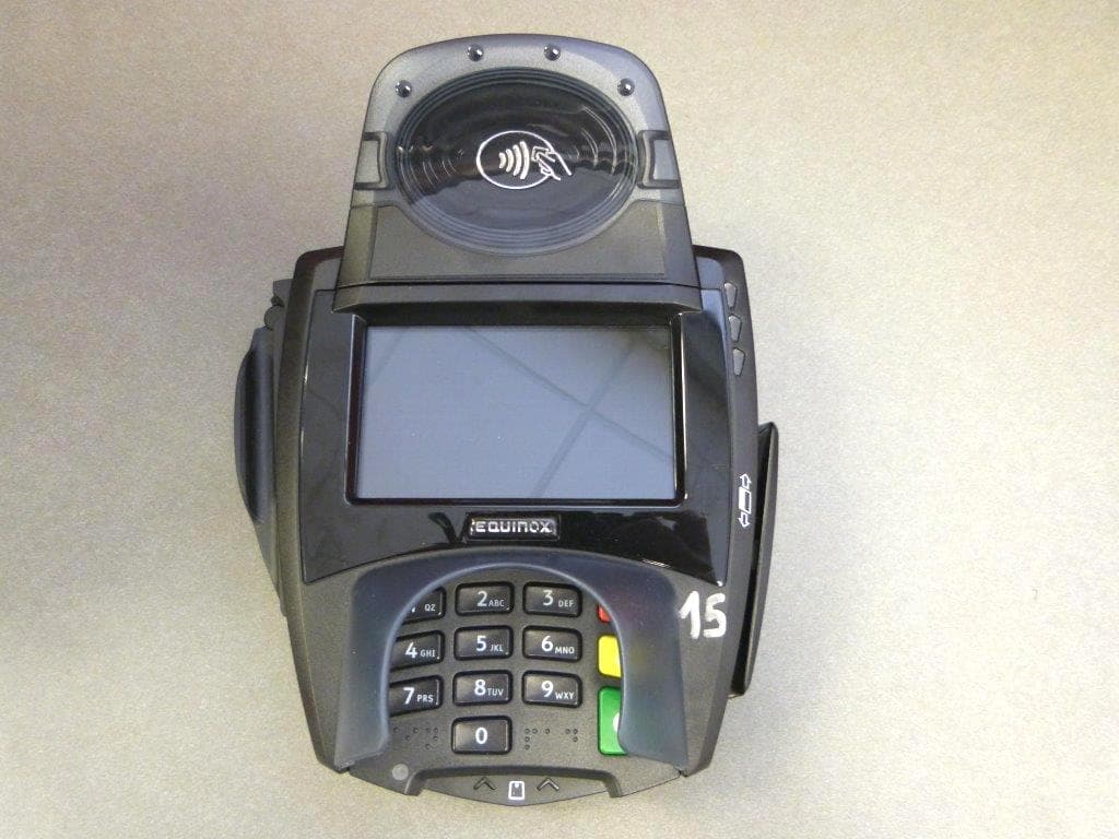
NVA00011
Jan 20, 2015Multilane POS Terminal
Equipment Class
DXX - Part 15 Low Power Communication Device Transmitter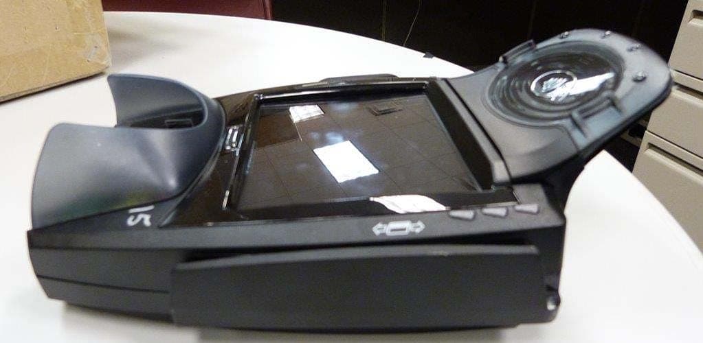
NVA00010
Sep 14, 2014Point of Sale Terminal
Equipment Class
DXX - Part 15 Low Power Communication Device Transmitter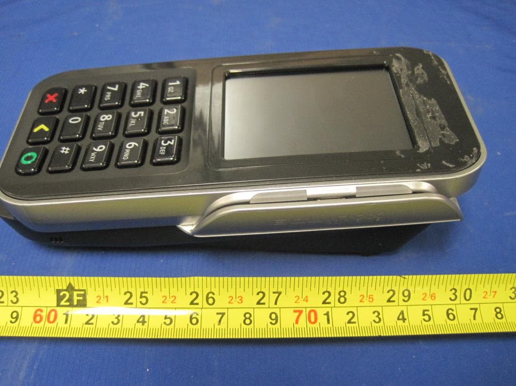
NVA00008
Sep 12, 2013Electronic POS Terminal
Equipment Class
DSS - Part 15 Spread Spectrum Transmitter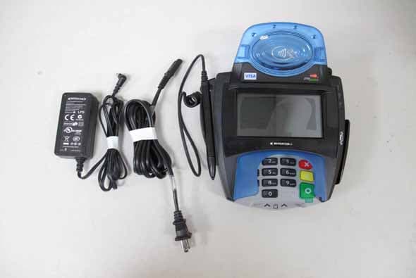
NVA00007
Aug 28, 2011Multilane POS Terminal
Equipment Class
DXX - Part 15 Low Power Communication Device Transmitter
NVA00005
Sep 08, 2010Multilane POS Terminal
Equipment Class
DXX - Part 15 Low Power Communication Device Transmitter