NVA030232-001Point of Sale Terminal
Equinox Payments LLC
Click to zoom
Application Details
- Equipment Class
- DXX - Part 15 Low Power Communication Device Transmitter
- Date of Grant
- Jan 11, 1999
- Application Purpose
- Original Equipment
- Date of Application
- Nov 17, 1998
- Equipment Note
- Point of Sale Terminal
- Frequency Range
- 916.50000000 - 916.50000000
- Company
- Equinox Payments LLC
- Country
- United States
Documents & Files
Document Text
Text extracted from the exhibit documents filed with the FCC. Open a document above to read the original.
Users Manual
HYPERCOM, INC. POS DEVELOPMENT 900 MHz WIRELESS ICE TERMINAL OPERATION INSTRUCTIONS HYPERCOM, INC. POS DEVELOPMENT 900 MHz WIRELESS ICE TERMINAL OPERATION INSTUCTIONS REV: A JANUARY, 1997 2 1. GENERAL PRODUCT DISCRIPTION ................................................................................................ 3 2. OPERATION .................................................................................................................................... 4 2.1 BASIC CONFIGURATION............................................................................................................ 5 3. INSTALLATION EXAMPLES............................................................................................................ 6 F IGURE 1 BASIC CONFIGURATION EXAMPLE.................................................................................... 5 F IGURE 2 INSTALLATION EXAMPLE................................................................................................... 6 HYPERCOM, INC. POS DEVELOPMENT 900 MHz WIRELESS ICE TERMINAL OPERATION INSTUCTIONS REV: A JANUARY, 1997 3 1. GENERAL PRODUCT DISCRIPTION Hypercom’s 900 MHz wireless ICE terminal in its current manifestation will take the standard POS transaction to the customer without the customer losing sight of his/her credit/debit/smart card. It will reduce the transaction time required by the vendor to run a card back and forth between the customer and the central POS terminal. The results of which are increased customer convenience, security and satisfaction, as well as reduced processing cost to the merchant. Features present on the ICE unit are as follows: 1. Signature Capture/Graphics Display. A touch screen display is used to allow a soft key menu and signature capture to be utilized. The Display contains 160 by 80 pixels which allows graphical use. 2. Keypad. A twelve key keypad is present on the unit containing the standard numeric numbers zero through nine. The last two keys are “CLEAR” and “ENTER”. 3. Battery Powered. Ice is capable of running on an internal battery or a 8-12Volt source providing power through the RJ11 port if tethered to a T7 terminal, LP3 loader or other device. The wireless unit is NOT designed to be used in a tethered mode. The unit will power up automatically when power is provided through the RJ11. There is a push button power switch located on the ICE for running on internal battery power. 4. Credit Card Reader. There is a standard track one and track two card reader located on ICE. 5. Smart Card Reader. There is a standard Smart/Memory Card reader located on the side of the unit. 6. SIMMs. Three SIMLocks are located on the bottom of the ICE unit for Vendor Mondex use. The ICE wireless uses an FXI01 900MHz radio transceiver board. This allows the ICE to be portable and the POS transaction can then take place wherever the card users may be. The ICE terminal communicates the transaction data via a 900MHz signal to a host terminal, which in turn communicates to a network. Once the transaction has been approved, the host terminal will inform the customer of the approval via the ICE unit display. Data encryption is provided by the host POS terminal and ICE device. Hypercom’s ICE 900MHz wireless system will consist of the following items: 1. HOST TERMINAL. This may be any of Hypercom’s POS terminal product with a PIN PAD port, and an external communication port (LAN or telephone), using the appropriate software such as T7, T7P, T77, T5000. 2. TERMINAL TRANSCRIVER INTERFACE. Hypercom model FTI 01 or for use with a single terminal transceiver, an adapter cable, Hypercom P/N: 810170-001. 3. TERMINAL TRANSCEIVER(S). Hypercom model FXV 01. 4. CUSTOMER PREMISIS WIREING. (If required.) 5. ICE TERMINAL. This must be an ICE wireless terminal with an FXI01 board and wireless software installed. HYPERCOM, INC. POS DEVELOPMENT 900 MHz WIRELESS ICE TERMINAL OPERATION INSTUCTIONS REV: A JANUARY, 1997 4 2. OPERATION Hypercom’s 900 MHz wireless POS terminal interface system is designed to be transparent to the user. The peripheral POS terminal device operation using the wireless POS terminal interface system is identical to its operation when the connection is through a cable between a peripheral POS terminal device and a host POS terminal. Hypercom’s 900 MHz wireless POS terminal interface system utilize radio transmitters and receivers certified in accordance with Federal Communications Commission (FCC) regulations, (CFR 47 Part 2 and Part 15) for use within the industrial, scientific, and medical band of frequencies between 902 MHz and 928 MHz. THIS DEVICE COMPLIES WITH PART 15 OF THE FCC RULES. OPERATION IS SUBJECT TO THE FOLLOWING TWO CONDITIONS: (1) THIS DEVICE MAY NOT CAUSE HARMFUL INTERFERENCE, AND (2) THIS DEVICE MUST ACCEPT ANY INTERFERENCE RECEIVED, INCLUDING INTERFERENCE THAT MAY CAUSE UNDESIRED OPERATION. HYPERCOM, INC. POS DEVELOPMENT 900 MHz WIRELESS ICE TERMINAL OPERATION INSTUCTIONS REV: A JANUARY, 1997 5 Operational distance between a terminal transceiver and a peripheral POS terminal is greatly affected by their environment. Obstructions such as walls and furniture as well as outside interfering signals may reduce the operational range. Software communication protocols have been implemented with in Hypercom’s 900 MHz wireless POS terminal interface system that should reduce these effects. 2.1 BASIC CONFIGURATION The example in figure 1 shows the basic configuration. The system was designed for a communication distance of from the terminal transceiver to the peripheral terminal device of less than 100 feet. Minimizing the coverage area reduces the possibility of creating interference to other communications systems sharing the same radio spectrum, a violation of FCC regulations. The short range design also reduces the chance of interference from outside sources. PN: 810170-001 SINGLE UNIT CABLE TERMINAL HOST TERMINAL TRANSCEIVER FXV01 PN: 020123-002 I.C.E. TERM INAL P/N: 030232-001 I.C.E. TERM INA…
Text truncated - open the document above for the full version.
Attestation Statements
The duty cycle is calculated as below. There are 1000 bit intervals in a .1 second period. A 50% duty cycle (500 high bits) was assumed to insure worst case scenario as the testing was done before the actual duty cycle was calculated. Sounds to me that the part recommended by RFM to help the receiver sensitivity may be a viable solution. I look forward to seeing if there is any improvement. Here are some snap shots from my data scope (real world). Looking at the short message lengths being used...73 bytes. Almost 30% of the .1 second interval we are quiet (nice for an emission average). Rough calculation ~1000 bit intervals in .1 second period (9600 baud) 73 Start bits (high) 4 STX (high) ~210 (high) Data typ.. ~300 high bits ~%30 of the .1 interval Longest message: 73 BYTES 55 5E 04 06 01 3C 01 01 0B 57 09 45 52 43 4F 4D 20 20 58 10 89 FF 03 30 01 58 10 89 FF 03 30 01 58 10 89 FF 03 30 01 58 10 89 FF 01 30 01 85 00 04 01 35 37 30 38 82 30 0A 31 31 32 33 34 35 36 37 38 39 30 84 20 00 19 A7 Message format 55 = STX 5E = MESSAGE SEQ NUMBER 04 = PACKET SEQ NUMBER 06 = CONTROL (ACK REQ...ETC) 01 = PACKET TYPE (01 = DATA, 02 = ACK, ETC) 3C = MESSAGE LENGTH 01 = MESSAGE ID 01 0B = DESTINATION ADDRESS 57 09 = SOURCE ADDRESS 09 52 43 ............>>>>>DATA<<<<<< LAST TWO BYTES 19 A7 -- CRC16 Shortest message (ACK) 13 BYTES 55 5E 04 00 02 00 00 57 09 01 0B 83 4F Message format 55 = STX 5E = MESSAGE SEQ NUMBER 04 = PACKET SEQ NUMBER 00 = CONTROL (ACK REQ...ETC) 02 = PACKET TYPE (01 = DATA, 02 = ACK, ETC) 00 = MESSAGE LENGTH 00 = MESSAGE ID 57 09 = DESTINATION ADDRESS 01 0B = SOURCE ADDRESS 19 A7 = CRC16
Operational Description
HYPERCOM, INC. POS DEVELOPMENT 900 MHz WIRELESS ICE TERMINAL THEORY OF OPERATION 1. ICE GENERAL DESCRIPTION The ICE unit will be used in Point of Sale “POS” type transactions as the direct interface to the card user. ICE as a product has been broken into many phases of which we are currently closing out the first phase. That is, the current ICE must communicate to a host terminal, whether by a tethered cord or by a wireless transmission, to complete a transaction. In future phases, peripheral devices will be added to increase the ICE functionality such that it can be utilized as a stand-alone unit, capable of doing full transactions. Standard features on the ICE unit will include a touch screen graphical display, a 12button keypad, track one and track two magnetic stripe card reader, and battery operation. Optional features include a SMART/Memory card reader, three SIMLocks, security processor, and a radio transceiver. These options will make the ICE unit very applicable to the specific needs of the customer. Future modules will be created that will increase the functionality of the ICE unit. They will attach to the ICE unit through a 60 pin connector on the back of the unit. 2. FUNCTIONAL BLOCKS The ICE unit can be broken down into various functions. Those functions and their associated descriptions are as follows: TouchPad Graphical Display Touch Screen Graphical Display. The ICE unit contains a 160 by 80 pixel display with multiple font capability. Both text and graphics modes are present on the display. The display itself contains a command register and a data register, which the Z80 processor communicates to via the processor data bus. A back light is used on the display to increase visibility of the display in less than perfect lighting. A resistive touch pad is attached (glued) to the top of the display for signature capture and soft key functionality. When a person touches the display a resistance is created, which also creates a voltage on the x and y axes. From this voltage the software is able to determine the touch location. Track 1 and Track 2 Card Reader. Functionality of this block is to read the data stored in the magnetic stripe of a credit or debit card. Currently our ICE unit will read track 1 and 2 data. There will possibly be track 3 capability in the future, if needed. 123 456 789 0C LEARENTER KEYPAD KEYPAD. The keypad on the ICE unit consists of ten numeric keys ( 0 through 9) and two special function keys. The special function keys are “CLEAR” and “ENTER”. Additional soft keys can be created using the touch screen display and software code. The OS code for the ICE unit continually scans the keypad for a key press during normal operation. Smart Card (OPTIONAL) SMART/Memory Card Reader. Ice will be capable of reading both memory cards and SMART Cards. Memory cards and SMART cards look like a credit card in size, but instead of containing a magnetic stripe they containing a PROM element that must be powered up then read. The name Memory card speaks for itself. The SMART card on the other hand is used as a cash card. Its ultimate goal would be to replace cash. To make it more secure, it can be used in conjunction with the three SIMLocks. SIM LOCK SIM LOCK SIM LOCK (OPTIONAL) SIMLocks. These devices are used in conjunction with SMART cards. A merchant card can be placed in each SIMLock. It then functions as a verification tool and cash register for the merchant when SMART cards are utilized. When a transaction takes place, the dollar amount is subtracted from the SMART card and added on to the Merchant card. At the end of the day the merchant can then call up the bank and transfer that amount into an account. FXI01 PCB (OPTIONAL) FXI01 Transceiver Board. In specific uses, it will be beneficial for the merchant to have a portable ICE unit. The FXI01 transceiver allows just that. Using a 900Mhz signal the radio ICE unit with the FXI01 and the proper software can communicate to a host terminal located at a central site. This allows the transaction to take place at any remote site within range of the host transceiver. NOTE: If the FXI01 used, the RJ11 has no use except for programming and the 60pin connector is blocked off with a plastic cover that is welded in place. RJ11 RS485/Power connector. Externally on the ICE is a RJ11 connector used to provide power (12 Volts) and RS485 communication only when tethered to a T7 terminal or other source. This port is also used for initial configuration load by the LP3 loader. During configuration the ICE terminal disables the RS485 port and allows the load to take place. Once completed the RS485 port can then be enabled. 60 PIN EXT. CONN. 60 Pin Connector. The ICE contains a 60pin connector that will be utilized as a peripheral expansion interface. Currently the data bus, as well as some key control signals, are present at this port to enable communication to some expansion modules currently being developed. BATTERY External Battery. Power for the ICE unit can be provided either through the RJ11 when tethered or through an external 4.0V battery. This external battery is keyed and fits into a slot on the side of the ICE unit. The lifetime of the battery is yet to be fully measured, but should fall in the range of two hours with normal operation when all power save modes are established by software. The battery also has a quick release for easy replacement. Z84C15 Microp rocessor Z8 Microp rocessor RA M FPG A ICE Control and Operation. The brains of the ICE unit are a Zilog Z84C15 microprocessor. Located on a secure module with a 4Mbit memory chip, the microprocessor is used to control all functionality and operation of the ICE unit. A Xilinx FPGA chip is used to reduce glue logic and for control registers needed to control internal and external peripherals. A Zilog Z8 microprocessor can be utilized if additional security is needed. Z84C15 Microprocessor TouchPad Graphical Display Track 1 and Track 2 Card Reader Z8 Microprocessor RAM …
Text truncated - open the document above for the full version.
Test Report
FCC ID: NVA030232-001 Report Number: B81029D1 114 OLINDA DRIVE, BREA, CALIFORNIA 92823 PHONE: (714) 579-0500 FAX: (714) 579-1850 Page 2 of 14 TABLE OF CONTENTS Section / TitlePAGE GENERAL REPORT SUMMARY4 SUMMARY OF TEST RESULTS4 1. PURPOSE5 2. ADMINISTRATIVE DATA6 2.1 Location of Testing6 2.2 Traceability Statement6 2.3 Cognizant Personnel6 2.4 Date Test Sample was Received6 2.5 Disposition of the Test Sample6 2.6 Abbreviations and Acronyms6 3. APPLICABLE DOCUMENTS7 4. Description of Test Configuration8 4.1 Description of Test Configuration - EMI8 5. LISTS OF EUT, ACCESSORIES AND TEST EQUIPMENT10 5.1EUT and Accessory List10 5.2 EMI Test Equipment11 6. TEST SITE DESCRIPTION12 6.1 Test Facility Description12 6.2 EUT Mounting, Bonding and Grounding12 7. Test Procedures13 7.1.1 Radiated Emissions (Spurious and Harmonics) Test13 8. CONCLUSIONS14 FCC ID: NVA030232-001 Report Number: B81029D1 114 OLINDA DRIVE, BREA, CALIFORNIA 92823 PHONE: (714) 579-0500 FAX: (714) 579-1850 Page 3 of 14 LIST OF APPENDICES APPENDIXTITLE AModifications to the EUT BAdditional Models Covered Under This Report CDiagrams, Charts and Photos • Test Setup Diagrams • Radiated and Conducted Emissions Photos • Antenna and Effective Gain Factors DData Sheets LIST OF TABLES TABLETITLE 1 Conducted Emissions Test Results 2 Radiated Emissions Test Results LIST OF FIGURES FIGURETITLE 1 Conducted Emissions Test Setup 2 Plot Map And Layout of Test Site FCC ID: NVA030232-001 Report Number: B81029D1 114 OLINDA DRIVE, BREA, CALIFORNIA 92823 PHONE: (714) 579-0500 FAX: (714) 579-1850 Page 4 of 14 GENERAL REPORT SUMMARY This electromagnetic emission test report is generated by Compatible Electronics Inc., which is an independent testing and consulting firm. The test report is based on testing performed by Compatible Electronics personnel according to the measurement procedures described in the test specifications given below and in the "Test Procedures" section of this report. The measurement data and conclusions appearing herein relate only to the sample tested and this report may not be reproduced in any form unless done so in full with the written permission of Compatible Electronics. This report must not be used to claim product endorsement by NVLAP or any other agency of the U.S. Government. Device Tested:POS Terminal Model: FXI 01 S/N: N/A Product Description:The EUT is a point of sale terminal. Modifications:The EUT was modified in order to meet the specifications. Please see list located in Appendix A. Manufacturer:Hypercom Corporation 2851 West Kathleen Road Phoenix, Arizona 85053 Test Date:October 29, 1998 Test Specifications : EMI requirements FCC Title 47, Part 15 Subpart C, Sections 15.205, 15.207 and 15.249 Test Procedure:ANSI C63.4: 1992 Test Deviations:The test procedure was not deviated from during the testing. SUMMARY OF TEST RESULTS TESTDESCRIPTIONRESULTS 1Conducted RF Emissions, 450 kHz - 30 MHzThis test was not performed because the EUT runs off a four volt battery only and cannot be powered by any device that runs off of the AC public mains. 2Radiated RF Emissions, 10 kHz - 9300 MHzComplies with the of FCC Title 47, Part 15 Subpart C, sections 15.205 and 15.249 FCC ID: NVA030232-001 Report Number: B81029D1 114 OLINDA DRIVE, BREA, CALIFORNIA 92823 PHONE: (714) 579-0500 FAX: (714) 579-1850 Page 5 of 14 1.PURPOSE This document is a qualification test report based on the Electromagnetic Interference (EMI) tests performed on the POS Terminal Model: FXI 01. The EMI measurements were performed according to the measurement procedure described in ANSI C63.4: 1992. The tests were performed in order to determine whether the electromagnetic emissions from the equipment under test, referred to as EUT hereafter, are within the specification limits defined by FCC Title 47, Part 15, Subpart C, sections 15.205, 15.207, and 15.249. FCC ID: NVA030232-001 Report Number: B81029D1 114 OLINDA DRIVE, BREA, CALIFORNIA 92823 PHONE: (714) 579-0500 FAX: (714) 579-1850 Page 6 of 14 2.ADMINISTRATIVE DATA 2.1Location of Testing The EMI tests described herein were performed at the test facility of Compatible Electronics, 114 Olinda Drive, Brea, California 92823. 2.2Traceability Statement The calibration certificates of all test equipment used during the test are on file at the location of the test. The calibration is traceable to the National Institute of Standards and Technology (NIST) . 2.3Cognizant Personnel Hypercom Corporation Robert “Bob” LindyElectronic Engineer, Hypercom POS Development Compatible Electronics Inc. Kyle FujimotoTest Engineer Scott McCutchanLab Manager 2.4Date Test Sample was Received The test sample was received on October 29, 1998 2.5Disposition of the Test Sample The test sample was returned to Hypercom Corporation on October 29, 1998. 2.6Abbreviations and Acronyms The following abbreviations and acronyms may be used in this document. RFRadio Frequency EMIElectromagnetic Interference EUTEquipment Under Test P/NPart Number S/NSerial Number HPHewlett Packard ITEInformation Technology Equipment CMLCorrected Meter Limit LISNLine Impedance Stabilization Network FCC ID: NVA030232-001 Report Number: B81029D1 114 OLINDA DRIVE, BREA, CALIFORNIA 92823 PHONE: (714) 579-0500 FAX: (714) 579-1850 Page 7 of 14 3.APPLICABLE DOCUMENTS The following documents are referenced or used in the preparation of this EMI Test Report. SPECTITLE FCC Title 47, Subpart C. FCC Rules - Radio frequency devices (including digital devices) – Intentional Radiators. ANSI C63.4 1992 Methods of measurement of radio-noise emissions from low-voltage electrical and electronic equipment in the range of 9 kHz to 40 GHz. FCC ID: NVA030232-001 Report Number: B81029D1 114 OLINDA DRIVE, BREA, CALIFORNIA 92823 PHONE: (714) 579-0500 FAX: (714) 579-1850 Page 8 of 14 4.DESCRIPTION OF TEST CONFIGURATION 4.1Description of Test Configuration - EMI Setup and operation of the equipment under test. Specifics of the EUT and Peripherals Tested The POS Terminal Model: FXI 01 (EUT) …
Text truncated - open the document above for the full version.
Contact Information
Applicant
Clint Woodworth(Manager Regulatory Compliance)
Technical Specifications
| # | Rule Parts | Frequency Range | Power Output |
|---|---|---|---|
| 1 | 15C | 916.5 MHz - 916.5 MHz | - |
Other Applications from Equinox Payments LLC
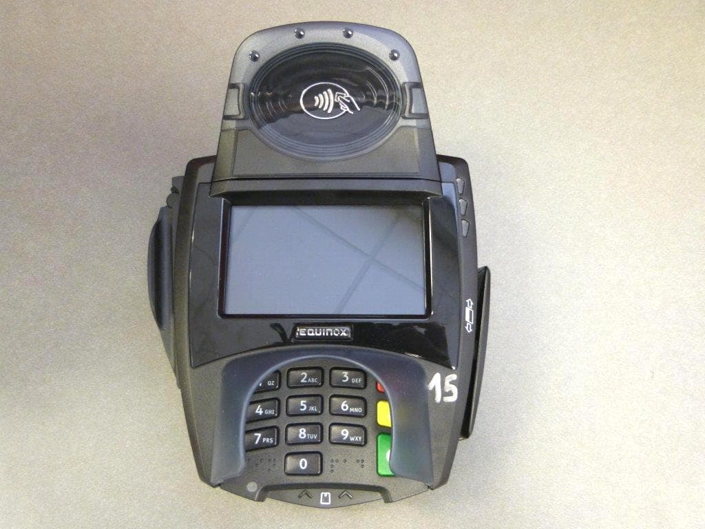
NVA00011
Jan 20, 2015Multilane POS Terminal
Equipment Class
DXX - Part 15 Low Power Communication Device Transmitter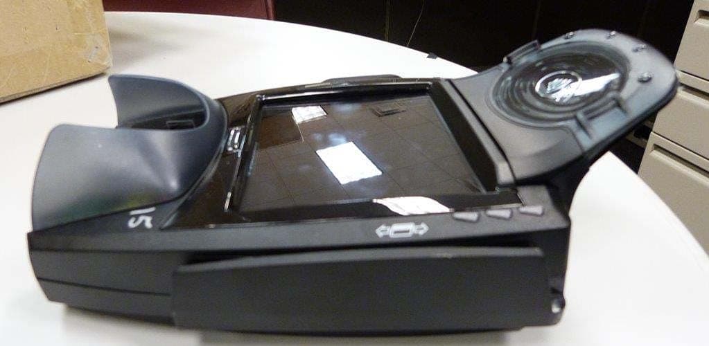
NVA00010
Sep 14, 2014Point of Sale Terminal
Equipment Class
DXX - Part 15 Low Power Communication Device Transmitter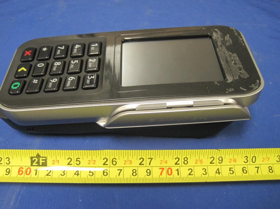
NVA00008
Sep 12, 2013Electronic POS Terminal
Equipment Class
DSS - Part 15 Spread Spectrum Transmitter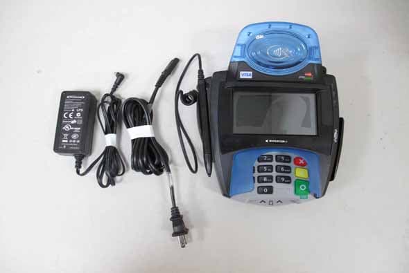
NVA00007
Aug 28, 2011Multilane POS Terminal
Equipment Class
DXX - Part 15 Low Power Communication Device Transmitter
NVA00005
Sep 08, 2010Multilane POS Terminal
Equipment Class
DXX - Part 15 Low Power Communication Device Transmitter