NVRBA14XAmplifier
Westell, Inc.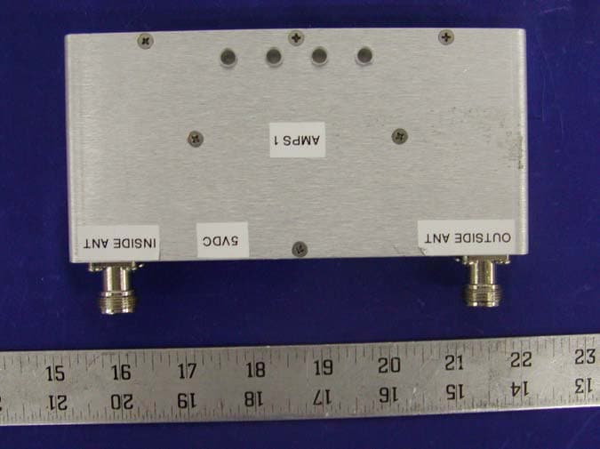
Click to zoom
Application Details
- Equipment Class
- AMP - Amplifier
- Date of Grant
- Aug 10, 2003
- Application Purpose
- Original Equipment
- Date of Application
- Aug 10, 2003
- Equipment Note
- Amplifier
- Frequency Range
- 824.04000000 - 848.92000000
- Company
- Westell, Inc.
- Country
- United States
Documents & Files
Document Text
Text extracted from the exhibit documents filed with the FCC. Open a document above to read the original.
Users Manual
Cellular Specialties, Inc. Model 140 Miniature In-Building Amplifier Operation and Users Manual 1 140 BDA Rev. 1 5/29/03 Table of Contents 1. Product Description Background Functional Description 2. General Specifications 3. Inspection and Installation Inspection of Contents Package Contents Installation Safety 2 140 BDA Rev. 1 5/29/03 1. Product Description Background The performance of a cell phone can be easily degraded when in enclosed structures where signals from a local cell site are not sufficient for reliable phone operation. The Model 140 Miniature In-Building Amplifier (Mini- IBA) was developed by Cellular Specialties, Inc. (CSI) to enhance cellular performance within these enclosed structures. Specifically, the Mini-IBA is designed to cover small areas such as home offices, small workshops, etc. Functional Description The Model 140 amplifier boosts the wireless network’s performance by providing amplification of both transmit and receive signals. The unit receives the portable phone’s signal through an inside antenna, amplifies it and then sends it to an outside antenna. This signal is referred to as the “Uplink”. The amplifier also receives signals from the Cell Site base station through the outside antenna. This signal is amplified and re-radiated to the portable phone and is referred to as the “Downlink”. It is necessary that sufficient signal be available at the outside antenna. The outside antenna is usually a directional type such as a “Yagi”, however an Omni-directional antenna may be used when the structure is located in close proximity to one or more cell sites. Inside antennas are usually Omni- directional although other types, such as low profile wall or ceiling mount, may be used for special installations. As shown in Figure 1, there are four stages of gain in the Downlink and four stages in the Uplink providing nominal gain of 40 dB in each link. The maximum linear output power is 160 milliwatts for the Uplink and 160 milliwatts for the Downlink. These levels are factory set and are maintained by an internal Automatic Gain Control (AGC) circuit. Four LED indicators on the unit indicate: • Green “Power” LED indicates that power is applied and the unit is operating. • Yellow “AGC” LED indicates that the gain of the Uplink and/or Downlink is being reduced to maintain the maximum power 3 140 BDA Rev. 1 5/29/03 output, which prevents spurious radio-frequency emissions from the amplifier. • Yellow “Isolation” LED indicates that the microcontroller in the unit has sensed instability due to insufficient isolation between the inside antenna and the outside antenna, and has reduced the gain of the amplifier. This is done to prevent oscillation, which can interfere with the handsets in the covered area and/or the wireless service provider’s base station. This “degraded mode” will be maintained until the amplifier power is disconnected and reconnected. The outside antenna should be placed as far as practical from the internal antenna, and should not be pointed toward the inside antenna. • Red “Shutdown” LED indicates that the gain of the unit has been reduced to minimum to prevent very strong input signals from overloading the amplifier. The amplifier will attempt to recover from this condition, initially at fifteen intervals and then at four- minute intervals. 4 140 BDA Rev. 1 5/29/03 2. General Specifications All specifications stated as typical unless otherwise noted. Cellular Specialties, Inc. reserves the right to change these specifications at any time without prior notice. Downlink Uplink Frequency Band 851-869 MHz (SMR) 869-894 MHz (Cellular) 806-824 MHz (SMR) 824-849 MHz (Cellular) Linear Gain (dB) 40 40 Typical Power Out (max) Linear * ** +22 dBm +22 dBm Noise Figure 6 dB 6 dB Propagation Delay <150 nsec. <150 nsec. Passband Ripple (max) 4 dB pk-pk 4 dB pk-pk Connectors Type N female Power Requirements +5 Vdc, 1.5 A Temperature -40º F to +122º C; -40º C to +50º C Dimensions 6.1 x 3 x 1 inch; 15.4 x 7.6 x 2.5 cm. Weight (amplifier only) 1.2 lb.; 0.55 kg. Indicator LEDs Power, AGC, Isolation, Shutdown Regulatory Approvals FCCID: NVRBA14X IC: 4307A-BA14X8 NOTES * The manufacturer’s rated output power of this equipment is for single carrier operation. For situations when multiple carrier signals are present, the rating must be reduced by 3.5 dB, especially where the output signal is re-radiated and can cause interference to adjacent band users. This power reduction is to be by means of input power or gain reduction and not by an attenuator at the output of the device. ** Maximum total output power without exceeding the FCC allowable emissions of –13 dBm. 5 140 BDA Rev. 1 5/29/03 3. Inspection and Installation Inspection Inspect the equipment as soon as possible after purchase. If any part of the equipment has been damaged in transit, report the damage to the transportation company and also to the company where purchased. Contents The unit package contains the following: Model 140 Amplifier Power Transformer, 110 volt to 5 volt User Manual Installation Note: The Installer should refer to the Safety Precautions, in the following section, for proper antenna selection and installation The installation of the Mini-IBA is relatively simple. If possible, measurements of the Received Signal Strength Indicator (RSSI) should be recorded as close as possible to the proposed outside antenna location. Optimum performance will be obtained with RSSI readings greater than –85 dBm. With the exact location of the outside antenna and the coordinates of the cell sites closest to the building in which the unit is being installed, the distance and bearings to each of the local cells can be determined. The first choice would be the closest site unless there is blockage in the form of buildings or terrain. If blockage exists, an alternate site may be available. If coordinates are not available, measure the signal strength at the outside antenna output by connecting a phone to the outside ante…
Text truncated - open the document above for the full version.
Cover Letter(s)
July 10, 2003 Federal Communications Commission Office of Engineering and Technology 7435 Oakland Mills Rd. Columbia, MD 21046 Subject: Request for Confidentiality Dear Sir or Madam: Cellular Specialties, Inc. respectfully requests that the schematic diagrams, block diagram, parts list, circuit description, and factory calibration procedure submitted with the application for certification under FCC ID NVRBA14X be withheld from public disclosure. This request is made under the provisions of Section 0.457 (d) of the Commission’s rules and Section 0.552 (b) (4) of the Freedom of Information Act. This product has been developed at considerable expense, and disclosure of this information would place Cellular Specialties, Inc. at a competitive disadvantage. Thank you for your attention to this matter. Sincerely yours, Donald C. Mills Vice President, System Products
External Photos
EXHIBIT C - EUT EXTERNAL PHOTOGRAPHS EUT – AMPS Top View EUT – AMPS Bottom View EUT – AMPS Port View EUT – SMR Top View EUT – SMR Bottom View EUT – SMR Prot View
ID Label/Location Info
EXHIBIT A - FCC PRODUCT LABELING AND WARNING STATEMENT FCC ID Label Specifications: Text is black or white in color and is left justified. Labels are silk-screened and shall be “permanently affixed” at a conspicuous location on the EUT. Proposed Label Location on EUT Bottom View of the EUT / Proposed Label Location FCC Warning Statement A FCC Warning Statement is provided in the product manual. FCC ID: NVRBA14X This device complies with part 15 of the FCC Rules. Operation is subject to the condition that this device does not cause harmful interference. Label Here
Test Report
Note: This test report is specially limited to the above client company and the product model only. It may not be duplicated without prior written consent of Bay Area Compliance Laboratory Corporation. This report must not be used by the client to claim product endorsement by NVLAP or any agency of the U.S. Government. FCC PART 22 & 90 TYPE APPROVAL EMI MEASUREMENT AND TEST REPORT For Cellular Specialties, Inc. 670 N. Commercial St. Manchester NH 03101 FCC ID: NVRBA14X 2003-07-16 This Report Concerns: Original Report Equipment Type: Amplifier Test Engineer: Benjamin Jing Report No.: R0305291 Test Date: 2003-07-09 Reviewed By: Ling Zhang / Prepared By: Bay Area Compliance Laboratory Corporation 230 Commercial Street Sunnyvale, CA 94085 Tel: (408) 732-9162 Fax: (408) 732 9164 Cellular Specialties, Inc. FCC ID: NVRBA14X Report # R0305291Rpt.doc Page 2 of 73 FCC PART 22 & 90 Type Approval report TABLE OF CONTENTS 1 - GENERAL INFORMATION..................................................................................................................................4 1.1 PRODUCT DESCRIPTION FOR EQUIPMENT UNDER TEST (EUT) ..............................................................................4 1.2 OBJECTIVE.............................................................................................................................................................4 1.3 RELATED SUBMITTAL(S)/GRANT(S) ......................................................................................................................4 1.4 TEST METHODOLOGY............................................................................................................................................4 1.5 TEST FACILITY.......................................................................................................................................................4 1.6 TEST EQUIPMENT LIST AND DETAILS.....................................................................................................................5 1.7 LOCAL SUPPORT EQUIPMENT LIST AND DETAILS...................................................................................................5 1.8 EXTERNAL I/O CABLING LIST AND DETAILS.........................................................................................................6 2 - SYSTEM TEST CONFIGURATION.....................................................................................................................7 2.1 JUSTIFICATION.......................................................................................................................................................7 2.2 SCHEMATICS/BLOCK DIAGRAM.............................................................................................................................7 2.3 TEST SETUP BLOCK DIAGRAM...............................................................................................................................7 2.4 EQUIPMENT MODIFICATIONS.................................................................................................................................7 3 - SUMMARY OF TEST RESULTS..........................................................................................................................8 4 – CONDUTED OUTPUT POWER..........................................................................................................................9 4.1 APPLICABLE STANDARD........................................................................................................................................9 4.2 TEST PROCEDURE..................................................................................................................................................9 4.3 TEST EQUIPMENT...................................................................................................................................................9 4.4 TEST RESULTS.....................................................................................................................................................10 5 - EMISSION BANDWIDTH ...................................................................................................................................11 5.1 APPLICABLE STANDARDS.....................................................................................................................................11 5.2 TEST PROCEDURE................................................................................................................................................11 5.3 TEST EQUIPMENT.................................................................................................................................................11 5.4 PLOTS OF OCCUPIED BANDWIDTH.......................................................................................................................11 6 – SPURIOUS EMISSIONS AT ANTENNA TERMINALS..................................................................................31 6.1 APPLICABLE STANDARDS.....................................................................................................................................31 6.2 TEST PROCEDURE................................................................................................................................................31 6.3 TEST EQUIPMENT.................................................................................................................................................31 6.4 TEST RESULTS.....................................................................................................................................................31 6.5 PLOTS OF OUT-OF-BAND EMISSIONS AT ANTENNA TERMINAL............................................................................31 7 - TWO-TONE TEST ................................................................................................................................................44 7.1 APPLICABLE STANDARDS......................…
Text truncated - open the document above for the full version.
Test Report
Cellular Specialties, Inc. FCC ID: NVRBA14X Report # R0305291Rpt.doc Page 31 of 73 FCC PART 22 & 90 Type Approval report 6 – SPURIOUS EMISSIONS AT ANTENNA TERMINALS 6.1 Applicable Standards According to FCC §2.1049, §22.917(a) and §90.210, on any frequency outside of the authorized operating frequency range, the power of any emission shall be attenuated below the transmitter power (P) by at least 43 + 10 log (P) dB. 6.2 Test Procedure The RF output of the transceiver was connected to a spectrum analyzer through appropriate attenuation. The resolution bandwidth of the spectrum analyzer was set at 1 MHz. Sufficient scans were taken to show any out of band emissions up to 10 th harmonic. 6.3 Test Equipment Hewlett Packard HP8566B Spectrum Analyzer Hewlett Packard HP 7470A Plotter Rohde & Schwarz SMIQ03B Signal Generator Rohde & Schwarz AMIQ I/Q Modulation Generator 6.4 Test Results 6.4.1 Test results for FCC Part 22, 824 – 849 MHz Uplink, 869 – 894 MHz Downlink Modulation Mode Channel Frequency (MHz) Measured Low 825.4 < -13dBm Mid 835.1 < -13dBm Up-link High 844.8 < -13dBm Low 870.7 < -13dBm Mid 880.4 < -13dBm CDMA Down-link High 890.1 < -13dBm 6.4.2 Test results for FCC Part 90, 806 – 824 MHz Uplink, 851 – 869 MHz Downlink Modulation Mode Channel Frequency (MHz) Measured Low 810.9 < -13dBm Mid 815.7 < -13dBm Up-link High 818.9 < -13dBm Low 854.5 < -13dBm Mid 859.4 < -13dBm TDMA Down-link High 864.2 < -13dBm 6.5 Plots of Out-of-Band Emissions at Antenna Terminal Please refer to plots hereinafter. Cellular Specialties, Inc. FCC ID: NVRBA14X Report # R0305291Rpt.doc Page 32 of 73 FCC PART 22 & 90 Type Approval report Plots for Part 22, 824 – 849 MHz Uplink, 869 – 894 MHz Downlink Cellular Specialties, Inc. FCC ID: NVRBA14X Report # R0305291Rpt.doc Page 33 of 73 FCC PART 22 & 90 Type Approval report Cellular Specialties, Inc. FCC ID: NVRBA14X Report # R0305291Rpt.doc Page 34 of 73 FCC PART 22 & 90 Type Approval report Cellular Specialties, Inc. FCC ID: NVRBA14X Report # R0305291Rpt.doc Page 35 of 73 FCC PART 22 & 90 Type Approval report Cellular Specialties, Inc. FCC ID: NVRBA14X Report # R0305291Rpt.doc Page 36 of 73 FCC PART 22 & 90 Type Approval report Cellular Specialties, Inc. FCC ID: NVRBA14X Report # R0305291Rpt.doc Page 37 of 73 FCC PART 22 & 90 Type Approval report Cellular Specialties, Inc. FCC ID: NVRBA14X Report # R0305291Rpt.doc Page 38 of 73 FCC PART 22 & 90 Type Approval report Plots for Part 90, 806 – 824 MHz Uplink, 851 – 869 MHz Downlink Cellular Specialties, Inc. FCC ID: NVRBA14X Report # R0305291Rpt.doc Page 39 of 73 FCC PART 22 & 90 Type Approval report Cellular Specialties, Inc. FCC ID: NVRBA14X Report # R0305291Rpt.doc Page 40 of 73 FCC PART 22 & 90 Type Approval report Cellular Specialties, Inc. FCC ID: NVRBA14X Report # R0305291Rpt.doc Page 41 of 73 FCC PART 22 & 90 Type Approval report Cellular Specialties, Inc. FCC ID: NVRBA14X Report # R0305291Rpt.doc Page 42 of 73 FCC PART 22 & 90 Type Approval report Cellular Specialties, Inc. FCC ID: NVRBA14X Report # R0305291Rpt.doc Page 43 of 73 FCC PART 22 & 90 Type Approval report
Test Report
Cellular Specialties, Inc. FCC ID: NVRBA14X Report # R0305291Rpt.doc Page 44 of 73 FCC PART 22 & 90 Type Approval report 7 - TWO-TONE TEST 7.1 Applicable Standards According to IS-138A (3.4.4), Intermodulation products must be attenuated below the rated power of the EUT by at least 43 +10log (P), equivalent to –13 dBm. 7.2 Test Procedure The RF output of the EUT was connected to a spectrum analyzer through appropriate attenuation. The resolution bandwidth of the spectrum analyzer was set at 30 kHz. Sufficient scans were taken to show any out of band emissions up to 10 th harmonic. Two input signals are equal in level (and can be raised equally), were send to the EUT. 7.3 Test Equipment Hewlett Packard HP8566B Spectrum Analyzer Hewlett Packard HP 7470A Plotter Rohde & Schwarz SMIQ03B Signal Generator Rohde & Schwarz AMIQ I/Q Modulation Generator 7.4 Test Results Modulation Mode Channel Measured Up-link Low < -13dBm Down-link Low < -13dBm Up-link Mid < -13dBm Down-link Mid < -13dBm Up-link High < -13dBm CDMA Down-link High < -13dBm 7.5 Plots of Two-Tone Test Result Please refer to plots hereinafter. Cellular Specialties, Inc. FCC ID: NVRBA14X Report # R0305291Rpt.doc Page 45 of 73 FCC PART 22 & 90 Type Approval report Cellular Specialties, Inc. FCC ID: NVRBA14X Report # R0305291Rpt.doc Page 46 of 73 FCC PART 22 & 90 Type Approval report Cellular Specialties, Inc. FCC ID: NVRBA14X Report # R0305291Rpt.doc Page 47 of 73 FCC PART 22 & 90 Type Approval report Cellular Specialties, Inc. FCC ID: NVRBA14X Report # R0305291Rpt.doc Page 48 of 73 FCC PART 22 & 90 Type Approval report Cellular Specialties, Inc. FCC ID: NVRBA14X Report # R0305291Rpt.doc Page 49 of 73 FCC PART 22 & 90 Type Approval report Cellular Specialties, Inc. FCC ID: NVRBA14X Report # R0305291Rpt.doc Page 50 of 73 FCC PART 22 & 90 Type Approval report Cellular Specialties, Inc. FCC ID: NVRBA14X Report # R0305291Rpt.doc Page 51 of 73 FCC PART 22 & 90 Type Approval report Cellular Specialties, Inc. FCC ID: NVRBA14X Report # R0305291Rpt.doc Page 52 of 73 FCC PART 22 & 90 Type Approval report Cellular Specialties, Inc. FCC ID: NVRBA14X Report # R0305291Rpt.doc Page 53 of 73 FCC PART 22 & 90 Type Approval report Cellular Specialties, Inc. FCC ID: NVRBA14X Report # R0305291Rpt.doc Page 54 of 73 FCC PART 22 & 90 Type Approval report 8 – RADIATED SPURIOUS EMISSION 8.1 Test Procedure Requirements: CFR 47, § 2.1053, § 22.917 and § 90.210. 8.2 Test Procedure The transmitter was placed on a wooden turntable, and it was transmitting into a non-radiating load which was also placed on the turntable. The measurement antenna was placed at a distance of 3 meters from the EUT. During the tests, the antenna height and polarization as well as EUT azimuth were varied in order to identify the maximum level of emissions from the EUT. The test was performed by placing the EUT on 3-orthogonal axis. The frequency range up to tenth harmonic of the fundamental frequency was investigated. Remove the EUT and replace it with substitution antenna. A signal generator was connected to the substitution antenna by a non-radiating cable. The absolute levels of the spurious emissions were measured by the substitution. Spurious emissions in dB = 10 lg (TXpwr in Watts/0.001) – the absolute level Spurious attenuation limit in dB = 43 + 10 Log 10 (power out in Watts) 8.3 Test Equipment CDI B100/200/300 Biconical Antennas EMCO Bi-logcon Antenna EMCO 3115 Horn Antenna HP 8566B Spectrum Analyzer Preamplifiers HP8640 Generator Non-radiating Load Cellular Specialties, Inc. FCC ID: NVRBA14X Report # R0305291Rpt.doc Page 55 of 73 FCC PART 22 & 90 Type Approval report 8.4 Test Result For Part 22, 824 – 849 MHz Uplink, 869 – 894 MHz Downlink Up-link: Low Frequency: -23.2 dBm at 1650 MHz Middle Frequency: -22.8 dBm at 1670 MHz High Frequency: -23.1 dBm at 1690 MHz Down-link: Low Frequency: -23.6 dBm at 1740 MHz Middle Frequency: -23 dBm at 1760 MHz High Frequency: -23.2 dBm at 1780 MHz For Part 90, 806 – 824 MHz Uplink, 851 – 869 MHz Downlink Up-link: Low Frequency: -37.3 dBm at 1620 MHz Middle Frequency: -36.8 dBm at 1630 MHz High Frequency: -35.1 dBm at 1640 MHz Down-link: Low Frequency: -37.4 dBm at 1710 MHz Middle Frequency: -37.6 dBm at 1720 MHz High Frequency: -37.1 dBm at 1730 MHz 8.4.1 Test Data for Part 22, 824 – 849 MHz Uplink, 869 – 894 MHz Downlink Up-Link, Low Channel at 825 MHz EUT Generator Standard Indicated Table Test Antenna Substitution AntennaCable Absolute FCC FCC Frequency Ampl. Angle Height Polar FrequencyLevel Polar H/VGain Loss Level Limit Margin MHz dBuV/m Degree Meter H/V MHz dBm CorrecteddBm dB dBm DBm 825 107.3 270 1.5 V 825 12.2 V 0 0.1 12.1 825 106.9 180 1.5 H 825 11.9 H 0 0.1 11.8 1650 63.9 110 1.5 H 1650 -42.7 H 6.8 0.3 -36.2 -13 -23.2 1650 59.8 30 1.2 V 1650 -46.5 V 6.8 0.3 -40 -13 -27 2475 46.7 180 1.2 V 2475 -49.9 V 7.6 0.5 -42.8 -13 -29.8 2475 43.2 270 1.5 H 2475 -51.4 H 7.6 0.5 -44.3 -13 -31.3 Cellular Specialties, Inc. FCC ID: NVRBA14X Report # R0305291Rpt.doc Page 56 of 73 FCC PART 22 & 90 Type Approval report Up-link, Mid. Channel at 835 MHz EUT Generator Standard Indicated Table Test Antenna Substitution AntennaCable Absolute FCC FCC Frequency Ampl. Angle Height Polar FrequencyLevel Polar H/VGain Loss Level Limit Margin MHz dBuV/m Degree Meter H/V MHz dBm CorrecteddBm dB dBm DBm 835 109.9 270 1.5 V 835 12.7 V 0 0.1 12.6 835 109.5 60 1.2 H 835 12.3 H 0 0.1 12.2 1670 64.6 110 1.5 H 1670 -42.3 H 6.8 0.3 -35.8 -13 -22.8 1670 60.5 30 1.2 V 1670 -46.2 V 6.8 0.3 -39.7 -13 -26.7 2505 47.5 180 1.5 V 2505 -49.6 V 7.6 0.5 -42.5 -13 -29.5 2505 43.1 230 1.2 H 2505 -51.2 H 7.6 0.5 -44.1 -13 -31.1 Up-Link, High Channel at 845 MHz EUT Generator Standard Indicated Table Test Antenna Substitution AntennaCable Absolute FCC FCC Frequency Ampl. Angle Height Polar FrequencyLevel Polar H/VGain Loss Level Limit Margin MHz dBuV/m Degree Meter H/V MHz dBm CorrecteddBm dB dBm DBm 845 108.2 330 1.5 V 845 12.4 V 0 0.1 12.3 845 106.7 60 1.5 H 845 11.8 H 0 0.1 11.7 1690 …
Text truncated - open the document above for the full version.
Test Report
Cellular Specialties, Inc. FCC ID: NVRBA14X Report # R0305291Rpt.doc Page 60 of 73 FCC PART 22 & 90 Type Approval report 9 – BAND EDGE TEST 9.1 Applicable Standards According to FCC §2.1049 and §22.917(b), when measuring the emission limits, carrier frequency shall be adjusted as close to the frequency block edges, both upper and lower. 9.2 Test Procedure The RF output of the transceiver was connected to a spectrum analyzer through appropriate attenuation. Adjust the carrier frequency as close to the frequency block edges both upper and lower. Sufficient scans were taken to show any out of band-edge emission. 9.3 Test Equipment Hewlett Packard HP8566B Spectrum Analyzer Hewlett Packard HP 7470A Plotter Rohde & Schwarz SMIQ03B Signal Generator Rohde & Schwarz AMIQ I/Q Modulation Generator 9.4 Plots of Out-of-Band-Edge Emissions at Antenna Terminal Please refer to plots hereinafter. Cellular Specialties, Inc. FCC ID: NVRBA14X Report # R0305291Rpt.doc Page 61 of 73 FCC PART 22 & 90 Type Approval report Band Edge Plots for CDMA Modulation Cellular Specialties, Inc. FCC ID: NVRBA14X Report # R0305291Rpt.doc Page 62 of 73 FCC PART 22 & 90 Type Approval report Cellular Specialties, Inc. FCC ID: NVRBA14X Report # R0305291Rpt.doc Page 63 of 73 FCC PART 22 & 90 Type Approval report Cellular Specialties, Inc. FCC ID: NVRBA14X Report # R0305291Rpt.doc Page 64 of 73 FCC PART 22 & 90 Type Approval report Cellular Specialties, Inc. FCC ID: NVRBA14X Report # R0305291Rpt.doc Page 65 of 73 FCC PART 22 & 90 Type Approval report Band Edge Plots for GSM Modulation Cellular Specialties, Inc. FCC ID: NVRBA14X Report # R0305291Rpt.doc Page 66 of 73 FCC PART 22 & 90 Type Approval report Cellular Specialties, Inc. FCC ID: NVRBA14X Report # R0305291Rpt.doc Page 67 of 73 FCC PART 22 & 90 Type Approval report Band Edge Plots for TDMA Modulation Cellular Specialties, Inc. FCC ID: NVRBA14X Report # R0305291Rpt.doc Page 68 of 73 FCC PART 22 & 90 Type Approval report Cellular Specialties, Inc. FCC ID: NVRBA14X Report # R0305291Rpt.doc Page 69 of 73 FCC PART 22 & 90 Type Approval report 10 – Modulation Characteristics This EUT only is an amplifier, it is not a transmitter. There is no modulating circuit in the EUT and no modulating characteristics measurement required. Cellular Specialties, Inc. FCC ID: NVRBA14X Report # R0305291Rpt.doc Page 70 of 73 FCC PART 22 & 90 Type Approval report 11 - FREQUENCY STABILITY This EUT only is an amplifier, it is not a transmitter. There is no oscillator circuit in the EUT, and no frequency stability measurement required. Cellular Specialties, Inc. FCC ID: NVRBA14X Report # R0305291Rpt.doc Page 71 of 73 FCC PART 22 & 90 Type Approval report 12 - CONDUCTED EMISSION Not Applicable. Cellular Specialties, Inc. FCC ID: NVRBA14X Report # R0305291Rpt.doc Page 72 of 73 FCC PART 22 & 90 Type Approval report 13 - RF EXPOSURE According to §1.1307(b)(1), systems operating under the provisions of this section shall be operated in a manner that ensures that the public is not exposed to radio frequency energy level in excess of the Commission’s guidelines. According to §1.1310 and §2.1093 RF exposure is calculated. Limits for Maximum Permissive Exposure (MPE) Frequency Range (MHz) Electric Field Strength (V/m) Magnetic Field Strength (A/m) Power Density (mW/cm 2 ) Averaging Time (minute) Limits for Occupational Population/Controlled Exposure 30-300 27.5 0.073 0.2 30 300-1500 / / f/1500 30 1500-100,000 / / 1.0 30 f = frequency in MHz * = Plane-wave equivalent power density MPE Prediction Predication of MPE limit at a given distance Equation from page 18 of OET Bulletin 65, Edition 97-01 S = PG/4πR² Where: S = power density P = power input to antenna G = power gain of the antenna in the direction of interest relative to an isotropic radiator R = distance to the center of radiation of the antenna Maximum peak output power at antenna input terminal: 21.4 (dBm ) Maximum peak output power at antenna input terminal: 138.04 (mW) Indoor Antenna: Prediction distance: 20 (cm) Predication frequency: 850 (MHz) Antenna Gain (typical): 8 (dBi) antenna gain: 6.31 (numeric) Power density at predication frequency at 20 cm: 0.173 (mW/cm 2 ) MPE limit for uncontrolled exposure at prediction frequency: 0.57 (mW/cm 2 ) Cellular Specialties, Inc. FCC ID: NVRBA14X Report # R0305291Rpt.doc Page 73 of 73 FCC PART 22 & 90 Type Approval report Outdoor Antenna: Prediction distance: 120 (cm) Predication frequency: 850 (MHz) Antenna Gain (typical): 10 (dBi) antenna gain: 10 (numeric) Power density at predication frequency at 120 cm: 0.00763 (mW/cm 2 ) MPE limit for uncontrolled exposure at prediction frequency: 0.57 (mW/cm 2 ) Test Result The EUT is a mobile device. The predicted power density level of indoor antenna at 20 cm is 0.173 mW/cm²; and the outdoor antenna at 120 c m is 0.00763. They are below the uncontrolled exposure limit of 0.57 mW/cm² at 850 MHz.
Contact Information
Applicant
Joseph K Gage(Compliance Engineer)
Test Firm
Bay Area Compliance LaboratoryJohn Chan
Technical Specifications
| # | Rule Parts | Frequency Range | Power Output | Emission |
|---|---|---|---|---|
| 8 | 22 | 824.04 MHz - 848.92 MHz | 138.00 mW | DXW |
Other Applications from Westell, Inc.

NVRDPSA81090-78
Jan 25, 2021700/800 MHZ DUAL BAND INDUSTRIAL BOOSTER
Equipment Class
B2I - Part 20 Industrial Booster (CMRS)
NVRCSIDRACELAAWS
Aug 23, 2015AWS Repeater
Equipment Class
B2I - Part 20 Industrial Booster (CMRS)
NVRCSICPBHMG-C4
Apr 30, 2013The Co-Pilot Beacon C4
Equipment Class
TNB - Licensed Non-Broadcast Station Transmitter
NVRCSICPBHMG-P4
Apr 28, 2013THE CO-PILOT BEACON P4
Equipment Class
PCB - PCS Licensed Transmitter
NVRCSICPBHMG-AW4
Dec 20, 2012The Co-Pilot Beacon
Equipment Class
TNB - Licensed Non-Broadcast Station Transmitter