NVRBA15X-01Bidirectional Amplifier
Westell, Inc.
Click to zoom
Application Details
- Equipment Class
- AMP - Amplifier
- Date of Grant
- Jul 07, 2003
- Application Purpose
- Original Equipment
- Date of Application
- Jul 07, 2003
- Equipment Note
- Bidirectional Amplifier
- Frequency Range
- 1930.00000000 - 1990.00000000
- Company
- Westell, Inc.
- Country
- United States
Documents & Files
Document Text
Text extracted from the exhibit documents filed with the FCC. Open a document above to read the original.
Users Manual
Cellular Specialties, Inc. Model 150 Miniature In-Building Amplifier Operation and Users Manual 1 150 BDA Rev. 1 5/29/03 Table of Contents 1. Product Description Background Functional Description Circuit Description 2. General Specifications 3. Inspection and Installation Inspection of Contents Package Contents Installation Safety 2 150 BDA Rev. 1 5/29/03 1. Product Description Background The performance of a cell phone can be easily degraded when in enclosed structures where signals from a local cell site are not sufficient for reliable phone operation. The Model 150 In-Building Amplifier (Mini-IBA) was developed to enhance wireless network performance within these enclosed structures. Specifically, the Model 150 is intended to cover relatively small areas such as home offices, workshops, offices etc. Functional Description The Model 150 amplifier boosts the wireless network’s performance by providing amplification of both transmit and receive signals. The unit receives the portable phone’s signal through an inside antenna, amplifies it and then sends it to an outside antenna. This signal is referred to as the “Uplink”. The amplifier also receives signals from the Cell Site base station through the outside antenna. This signal is amplified and re-radiated to the portable phone and is referred to as the “Downlink”. It is necessary that sufficient signal be available at the outside antenna. The outside antenna is usually a directional type such as a “Yagi”, however an Omni-directional antenna may be used when the structure is located in close proximity to one or more cell sites. Inside antennas are usually Omni- directional although other types, such as low profile wall or ceiling mount, may be used for special installations. As shown in Figure 1, there are four stages of gain in the Downlink and four stages in the Uplink for maximum gain of 50 dB in each link. The maximum linear output power is 125 milliwatts for the Uplink and 80 milliwatts for the Downlink. These levels are factory set and are maintained by an internal Automatic Gain Control (AGC) circuit. Four LED indicators on the unit indicate: • Green “Power” LED indicates that power is applied and the unit is operating. • Yellow “AGC” LED indicates that the gain of the Uplink and/or Downlink is being reduced to maintain the maximum power 3 150 BDA Rev. 1 5/29/03 output, which prevents spurious radio-frequency emissions from the amplifier. • Yellow “Isolation” LED indicates that the microcontroller in the unit has sensed instability due to insufficient isolation between the inside antenna and the outside antenna, and has reduced the gain of the amplifier. This is done to prevent oscillation, which can interfere with the handsets in the covered area and/or the wireless service provider’s base station. This “degraded mode” will be maintained until the amplifier power is disconnected and reconnected. The outside antenna should be placed as far as practical from the internal antenna, and should not be pointed toward the inside antenna. • Red “Shutdown” LED indicates that the gain of the unit has been reduced to minimum to prevent very strong input signals from overloading the amplifier. The amplifier will attempt to recover from this condition, initially at fifteen intervals and then at four- minute intervals. 4 150 BDA Rev. 1 5/29/03 Circuit Description Uplink Amplifier The uplink amplifier circuit consists of four stages of gain. Each gain stage is a monolithic integrated circuit (MMIC) mounted to a printed circuit board (PCB). The signal received by the inside antenna is directed to the 1 st MMIC stage by a frequency diplexer, which separates the uplink frequency band (1850 - 1910 MHz) from the downlink frequency band (1930 - 1990 MHz). This signal is amplified by three additional MMIC stages and filtered by a ceramic bandpass filter, then directed to an identical diplexer at the output of the fourth stage. A variable attenuator is provided to implement Automatic Gain Control (AGC) in the Model 150, and is controlled by the Control circuit (described below). All stages are biased for linear operation. The overall gain from the inside antenna terminal to the outside antenna terminal is nominally 50 dB. Each diplexer / filter combination provides more than 65 dB of rejection between the uplink amplifier chain and the downlink. Downlink Amplifier The downlink circuit is identical in operation to the uplink, providing four stages of MMIC amplification. The major differences are the downlink frequency (1930 – 1990 MHz.) and signal flow in the opposite direction. Controller Operation of the Model 150 amplifier is monitored and controlled by a microcontroller. The primary functions of the microcontroller are: maintain linear operation by controlling the gain of the unit to prevent spurious radio- frequency emissions; shut down the amplifier in the event of a severe overload condition which exceeds the range of the AGC circuit; and to detect and reduce the amplifier’s gain to prevent instability of the unit in the event that the isolation between the outside antenna and the inside antenna is insufficient. 5 150 BDA Rev. 1 5/29/03 Power Supply All of the MMIC amplification stages, in both the uplink and downlink, operate from a single supply voltage of +5 Vdc. All internal dc circuits are filtered and de-coupled from the RF circuits. A high-efficiency 115 Volt AC to 5 Volt DC “Wall” supply is provided with the unit. The current requirement at 5 Volts DC is less than 1.2 Amperes. 6 150 BDA Rev. 1 5/29/03 2. General Specifications All specifications stated as typical unless otherwise noted. Cellular Specialties, Inc. reserves the right to change these specifications at any time without prior notice. Downlink Uplink Frequency Band 1930 – 1990 MHz 1850 – 1910 MHz Linear Gain (dB) 50 50 Typical Power Out (max) Linear * ** +19 dBm (80 mW) +21 dBm (125 mW) Noise Figure 6 dB 6 dB Propagation Delay < 150 nsec. < 150 nsec. Passband Ripple (max) 4 dB p…
Text truncated - open the document above for the full version.
Cover Letter(s)
May 21, 2003 Mr. Scott Wentworth Retlif Laboratories 101 New Boston Rd. Goffstown, NH 03045 Re: Adjustment of the Model 150 In-building Amplifier in the Field The CSI Model 150 In-Building Amplifier provides no adjustments to the technician during installation and maintenance activities. Frequency response, gain, and power thresholds are factory set and in no circumstance are they to be adjusted in the field. Regards, Donald C. Mills Vice President, System Products
Cover Letter(s)
May 21, 2003 Federal Communications Commission Office of Engineering and Technology 7435 Oakland Mills Rd. Columbia, MD 21046 Subject: Request for Confidentiality Dear Sir or Madam: Cellular Specialties, Inc. respectfully requests that the schematic diagrams, block diagram, parts list, and circuit descriptions submitted with the application for certification under FCC ID NVRBA15X-01 be withheld from public disclosure. This request is made under the provisions of Section 0.457 (d) of the Commission’s rules and Section 0.552 (b) (4) of the Freedom of Information Act. This product has been developed at considerable expense, and disclosure of this information would place Cellular Specialties, Inc. at a competitive disadvantage. Thank you for your attention to this matter. Sincerely yours, Donald C. Mills Vice President, System Products
ID Label/Location Info
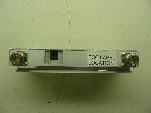
FCC ID: NVRBA15X-01 IC: 4307A-BA15X19 This device complies with Parts 24 and 2 of the FCC rules, and with Industry Canada specification RSS-131. Regulatory compliance label for CSI-BDA150 (PCS Band).
Parts List/Tune Up Info
May 21, 2003 Mr. Scott Wentworth Retlif Laboratories 101 New Boston Rd. Goffstown, NH 03045 Re: Adjustment of the Model 150 In-building Amplifier in the Field The CSI Model 150 In-Building Amplifier provides no adjustments to the technician during installation and maintenance activities. Frequency response, gain, and power thresholds are factory set and in no circumstance are they to be adjusted in the field. Regards, Donald C. Mills Vice President, System Products
RF Exposure Info
Evaluation of the CSI Model 150 BDA For Compliance with FCC Guidelines For Human Exposure to Radio Frequency Electromagnetic Fields 21 May, 2003 General The CSI Model 150 Bi-directional amplifier is considered to be a “mobile” device operating in the Land Mobile Service authorized under part 24. As such, the equipment is required to be evaluated for RF exposure if operated above 1.5 GHz with an effective radiated power (ERP) of 3 watts or more, as defined in 2.1091 of FCC rules. Downlink For the downlink portion of the Model 150 BDA, the maximum rated output power is not greater than +22dbm (100 mW). As stated in the Model 150 Manual, the maximum authorized antenna gain is 8 dBi, corresponding to a high-performance indoor directional antenna. Neglecting cable losses, the worst-case EIRP will be 1.0 watts or an ERP of 0.610 watts, (ERP=EIRP/1.64). This is well below 3 watts, and therefore excludes the downlink from routine evaluation. The Cautions in the Model 150 manual clearly define the antenna selection and installation criteria in order to maintain a minimum 20- centimeter separation. Uplink For the uplink portion of the BDA, the maximum rated output power is not greater than +22 dbm (158 mW). As stated in the Model 150 Manual, the maximum authorized antenna gain is 14 dBi, corresponding to a high-performance outdoor directional antenna. Neglecting cable losses, the worst case EIRP will be 3.98 watts, or an ERP of 2.43 watts (ERP = EIRP / 1.64). This is below 3 watts, and therefore excludes the uplink from routine evaluation. The Cautions in the Model 150 manual clearly define the antenna selection and installation criteria required to maintain a minimum 120-centimeter separation.
Test Report
MODEL 150 POWER PER CHANNEL ChannelsUpLinkDownLink dBmdBm 121.119.2 217.115.2 314.812.9 413.111.2 511.89.9 610.88.9 79.98.0 89.17.2 98.46.5 107.85.9 117.35.4 126.84.9 136.34.4 145.94.0 155.53.6 165.13.2 Power per Channel.xls6/3/2003
Contact Information
Applicant
Joseph K Gage(Compliance Engineer)
Technical Contact
Retlif Testing LaboratoriesScott Wentworth
[email protected]603-497-4600
101 New Boston Road · Goffstown, New Hampshire · United States
Non-Technical Contact
Retlif Testing LaboratoriesScott Wentworth
[email protected]603-497-4600
Test Firm
Retlif Testing LaboratoriesScott Wentworth
Technical Specifications
| # | Rule Parts | Frequency Range | Power Output | Emission |
|---|---|---|---|---|
| 2 | 24 | 1.93 GHz - 1.99 GHz | 80.00 mW | DXW |
Other Applications from Westell, Inc.

NVRDPSA81090-78
Jan 25, 2021700/800 MHZ DUAL BAND INDUSTRIAL BOOSTER
Equipment Class
B2I - Part 20 Industrial Booster (CMRS)
NVRCSIDRACELAAWS
Aug 23, 2015AWS Repeater
Equipment Class
B2I - Part 20 Industrial Booster (CMRS)
NVRCSICPBHMG-C4
Apr 30, 2013The Co-Pilot Beacon C4
Equipment Class
TNB - Licensed Non-Broadcast Station Transmitter
NVRCSICPBHMG-P4
Apr 28, 2013THE CO-PILOT BEACON P4
Equipment Class
PCB - PCS Licensed Transmitter
NVRCSICPBHMG-AW4
Dec 20, 2012The Co-Pilot Beacon
Equipment Class
TNB - Licensed Non-Broadcast Station Transmitter