NVRBA56X-01BiDirectional Amplifier
Westell, Inc.
Click to zoom
Application Details
- Equipment Class
- AMP - Amplifier
- Date of Grant
- Jan 21, 2003
- Application Purpose
- Original Equipment
- Date of Application
- Jan 21, 2003
- Equipment Note
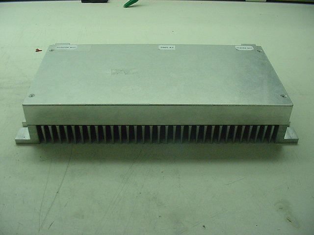
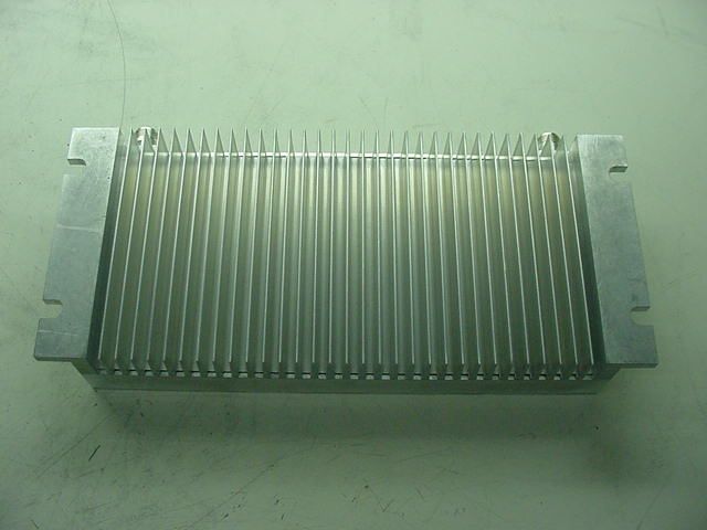
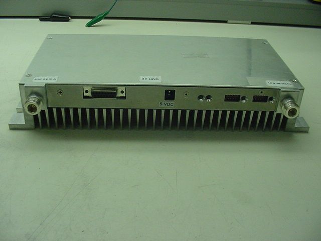
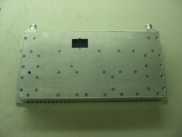
- BiDirectional Amplifier
- Frequency Range
- 851.00000000 - 866.00000000
- Company
- Westell, Inc.
- Country
- United States
Documents & Files
Document Text
Text extracted from the exhibit documents filed with the FCC. Open a document above to read the original.
Users Manual
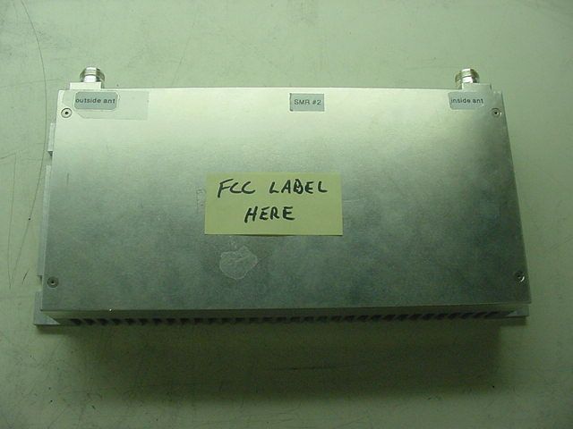
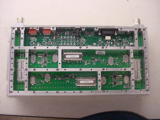
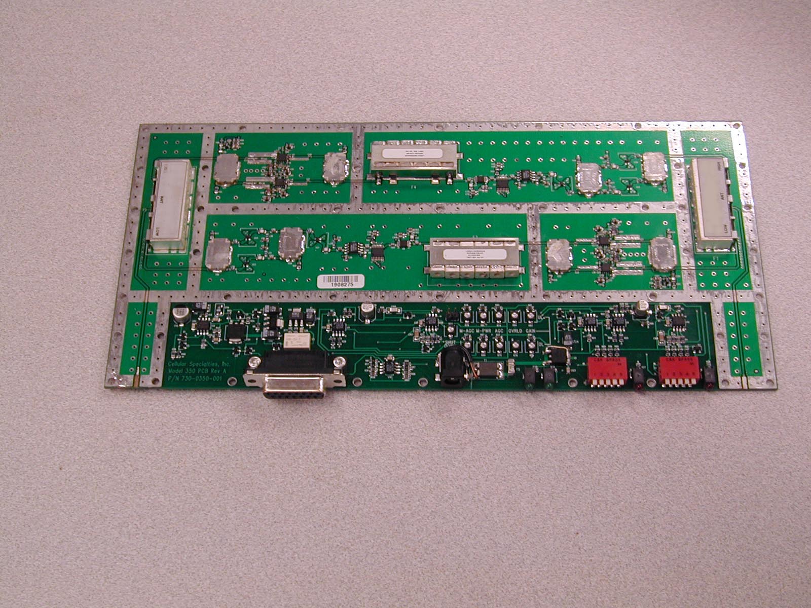
Cellular Specialties, Inc. Model 565SMR In-Building Amplifier Installation and Users Manual The serial number may be found on the label on the rear panel of the unit. For your convenience, note this number below, and retain this manual, along with proof of purchase , to serve as a permanent record of your purchase in the event of a theft, or for future reference. MODEL NUMBER NAME OF COMPANY DATE OF PURCHASE 565 SERIAL NUMBER FCC ID: NVRBA56X-01 IC: 4307A-BA56X8 THIS DEVICE COMPLIES WITH PARTS 90 AND 2 OF THE FCC RULES, AND WITH INDUSTRY CANADA SPECIFICATION RSS-131. The term “IC” before the certification/registration number only signifies that the Industry Canada specifications were met. DISCLAIMER All information and statements contained herein are accurate to the best of the knowledge of Cellular Specialties, but Cellular Specialties makes no warranty with respect thereto, including without limitation any results which may be obtained from the products described herein or the infringement by such products of any proprietary rights of any persons. Use or application of such information or statements is at the user's sole risk, without any liability on the part of Cellular Specialties, Inc. Nothing herein shall be construed as license or of recommendation for use, which infringes upon any proprietary rights of any person. Product material and specifications are subject to change without notice. All sales of the product or products described herein are subject to Cellular Specialties' standard terms of sale and the specific terms of any particular sale. TABLE OF CONTENTS 1.0 SAFETY GUIDELINES 3 2.0 PRODUCT DESCRIPTION 4 MECHANICAL OUTLINE DRAWING 5 3.0 GENERAL SPECIFICATIONS 6 4.0 INSTALLATION 7 5.0 AMPLIFIER ADJUSTMENT 9 6.0 TROUBLESHOOTING 10 MANUAL565 SMR REV A 960-1008-001 2 SAFETY GUIDELINES 1.0 The general safety information in this guideline applies to both operating and service personnel. Specific warnings and cautions will be found in other parts of this manual where they apply, but may not appear in this summary. Failure to comply with these precautions or specific warnings elsewhere in the manual violates safety standards of design, manufacture, and intended use of equipment. Cellular Specialties, Inc. assumes no liability for the customer's failure to comply with these requirements. ! ¾ GROUNDING This amplifier system is designed to operate from single-phase 120VAC power and should always be operated with both the neutral and ground wires properly connected. Do not remove or otherwise alter the grounding lug on the power cord. ¾ EXPLOSIVE ATMOSPHERES To avoid explosion or fire, do not operate this product in the presence of flammable gases or fumes. ¾ LIGHTNING DANGER Do not install or make adjustments to this unit during an electrical storm. ¾ NO USER SERVICEABLE PARTS INSIDE HAZARDOUS VOLTAGES ARE PRESENT WHEN THE COVER IS REMOVED. Opening the chassis will void your warranty. If you suspect a malfunction with this product, call your dealer or the Cellular Specialties Support Line at (603) 626-6677. MANUAL565 SMR REV A 960-1008-001 3 PRODUCT DESCRIPTION Cellular Specialties, Inc. developed the Model 565SMR Bi-Directional Amplifier (BDA) for use in enclosed structures where sufficient signal from local cell sites to operate cell phones was unavailable within the building. It is necessary that sufficient signal be available on the roof of the structure. The BDA is connected to an external antenna, usually on the roof, and to one or more internal antennas placed strategically throughout the area where phone service is desired. The external antenna is an omni-directional antenna. Internal antennas are usually omni-directional although various other types may be used for certain installations. The BDA amplifies both the "uplink" (phone to tower) and "downlink" (tower to phone) signals thus facilitating communications to and from the local cell site. There are four amplification stages on the downlink and four on the uplink for a total of +65dB nominal gain for each link. Both links have manual gain control settings accessed through DIP switches on the rear of the unit plus an AGC control for both the uplink and downlink. There are LED indicators for power on, transmitter on, uplink overload and downlink overload. An automatic amplifier safety shutdown circuit is also provided, which will disable the transmitters for ten seconds should the uplink or downlink overloads be reached to prevent excessive intermodulation and oscillation. The BDA is equipped with an interface connector designed for use with the optional CSI-MHH External Monitor. The pin-out of the MONITOR connector is shown below. Pin Description 1 Alarm Relay - Common 2 N/C 3 Shutdown (Input TTL) 4 Uplink Power 5 Alarm Relay – Active Open 6 N/C 7 Uplink AGC Level 8 Ground 9 Alarm Relay – Active Closed 10 N/C 11 Downlink AGC Level 12 +5 VDC 13 Uplink Overload 14 Downlink Overload 15 Downlink Power 2.0 MANUAL565 SMR REV A 960-1008-001 4 MANUAL565 SMR REV A 960-1008-001 5 OUTLINE DRAWING 3.0 GENERAL SPECIFICATIONS All specifications stated as typical unless otherwise noted. Uplink (Phone to Tower) Downlink (Tower to Phone) Frequency (SMR) 806-821 MHz 851-866 MHz Pass Band Ripple ± 2.5 dB ± 2.5 dB Gain @ Zero Attenuation +65dB +65dB Gain Adjustment Range -30dB -30dB Linear Output Power * ** +27dBm +27dBm Noise Figure 4.5dB 4.5dB Maximum Input Power*** +15dBm +15dBm VSWR 1.7:1 Max Propagation Delay <200 nsec. Impedance 50 Ohms Connectors ‘N’ Female Power Requirements +5 VDC @ 4000mA Size 5.3” x 12.4” x 1.9” Weight 8.8 Lbs., 4 kg Operating Temperature 0 to +45 ° C Indicator LEDs Power, Transmitter On, Uplink Overload, Downlink Overload Controls AGC switch, Uplink and Downlink attenuation switches 0-30dB in 2dB steps. NOTES * The manufacturer’s rated output power of this equipment is for single carrier operation. For situations when multiple carrier signals are present, the rating must be reduced by 3.5 dB, especially where th…
Text truncated - open the document above for the full version.
Cover Letter(s)
November 22, 2002 Federal Communications Commission Office of Engineering and Technology 7435 Oakland Mills Rd. Columbia, MD 21046 Subject: Request for Confidentiality Dear Sir or Madam: Cellular Specialties, Inc. respectfully requests that the schematic diagrams, block diagram, and circuit descriptions submitted with the application for certification under FCC ID NVRBA56X-01 be withheld from public disclosure. This request is made under the provisions of Section 0.457 (d) of the Commission’s rules and Section 0.552 (b) (4) of the Freedom of Information Act. This product has been developed at considerable expense, and disclosure of this information would place Cellular Specialties, Inc. at a competitive disadvantage. Thank you for your attention to this matter. Sincerely yours, Donald C. Mills Vice President, System Products
ID Label/Location Info
FCC ID: NVRBA56X-01 IC: 4307A-BA56X8 This device complies with Parts 90 and 2 of the FCC rules, and with Industry Canada specification RSS-131. Regulatory compliance label for CSI-BDA565 (800 MHz. SMR Band).
Parts List/Tune Up Info
November 22, 2002 Mr. Scott Wentworth Retlif Laboratories 101 New Boston Rd. Goffstown, NH 03045 Re: Adjustment of the Model 565 In-building Amplifier in the Field The CSI Model 565 In-Building Amplifier offers only adjustment of attenuation (below its factory-set maximum gain level) to the technician during installation and maintenance activities. This adjustment is dependent on the physical environment in which the amplifier is to be installed and is described in the Installation and Users Manual. This is the only adjustment accessible without opening the amplifier. Frequency response and gain thresholds are factory set and in no circumstance are they to be adjusted in the field. Regards, Donald C. Mills Vice President, System Products
RF Exposure Info
Evaluation of the CSI Model 565 SMR BDA For Compliance with FCC Guidelines For Human Exposure to Radio Frequency Electromagnetic Fields 18 December 2002 General The CSI Model 565 SMR Bi-directional amplifier is considered to be a “mobile” device operating in the Land Mobile Service authorized under part 90. As such, the equipment is required to be evaluated for RF exposure if operated below 1.5 GHz with an effective radiated power (ERP) of 1.5 watts or more, as defined in 2.1091 of FCC rules. Downlink For the downlink portion of the Model 565 SMR BDA, the maximum rated output power is not greater than +29dbm (794 mW). As stated in the Model 565 SMR Manual, the maximum authorized antenna gain is 3 dBi, corresponding to a typical Omni-Directional antenna. Neglecting cable losses, the worst-case EIRP will be 1.59 watts or an ERP of 0.97 watts, (ERP=EIRP/1.64). This is well below the 1.5 watts and therefore excludes the downlink from routine evaluation. The Cautions in the Model 565 SMR manual clearly define the antenna selection and installation criteria in order to maintain a minimum 20- centimeter separation. Uplink For the uplink portion of the BDA, the maximum rated output power is not greater than +28 dbm (631 mW). As stated in the Model 565 SMR Manual, the maximum authorized antenna gain is 3 dBi, corresponding to a typical Omni-Directional antenna. Neglecting cable losses, the worst case EIRP will be 1.59 watts, or an ERP of 0.97 watts (ERP = EIRP / 1.64). This is well below the 1.5 watts and therefore excludes the uplink from routine evaluation. The Cautions in the Model 565 SMR manual clearly define the antenna selection and installation criteria required to maintain a minimum 20-centimeter separation.
Test Report
MODEL 565 POWER PER CHANNEL ChannelsUpLinkDownLink dBmdBm 127.027.0 223.023.0 320.720.7 419.019.0 517.717.7 616.716.7 715.815.8 815.015.0 914.314.3 1013.713.7 1113.213.2 1212.712.7 1312.212.2 1411.811.8 1511.411.4 1611.011.0 Power per Channel-smr.xls12/18/2002
Contact Information
Applicant
Joseph K Gage(Compliance Engineer)
Technical Contact
Retlif Testing LaboratoriesScott Wentworth
[email protected]603 497-4600
101 New Boston Road · Goffstown, New Hampshire · United States
Non-Technical Contact
Retlif Testing LaboratoriesScott Wentworth
[email protected]603 497-4600
Test Firm
Retlif Testing LaboratoriesScott Wentworth
Technical Specifications
| # | Rule Parts | Frequency Range | Power Output | Emission |
|---|---|---|---|---|
| 2 | 9 | 851 MHz - 866 MHz | 560.00 mW | DXW |
Other Applications from Westell, Inc.

NVRDPSA81090-78
Jan 25, 2021700/800 MHZ DUAL BAND INDUSTRIAL BOOSTER
Equipment Class
B2I - Part 20 Industrial Booster (CMRS)
NVRCSIDRACELAAWS
Aug 23, 2015AWS Repeater
Equipment Class
B2I - Part 20 Industrial Booster (CMRS)
NVRCSICPBHMG-C4
Apr 30, 2013The Co-Pilot Beacon C4
Equipment Class
TNB - Licensed Non-Broadcast Station Transmitter
NVRCSICPBHMG-P4
Apr 28, 2013THE CO-PILOT BEACON P4
Equipment Class
PCB - PCS Licensed Transmitter
NVRCSICPBHMG-AW4
Dec 20, 2012The Co-Pilot Beacon
Equipment Class
TNB - Licensed Non-Broadcast Station Transmitter