NVRCSI-DSP25XAWBidirectional Amplifier
Westell, Inc.
Click to zoom
Application Details
- Equipment Class
- TNB - Licensed Non-Broadcast Station Transmitter
- Date of Grant
- Nov 02, 2010
- Application Purpose
- Original Equipment
- Date of Application
- Nov 02, 2010
- Equipment Note
- Bidirectional Amplifier
- Frequency Range
- 2110.00000000 - 2155.00000000
- Company
- Westell, Inc.
- Country
- United States
Documents & Files
Document Text
Text extracted from the exhibit documents filed with the FCC. Open a document above to read the original.
Users Manual
CSI-DSP85-250-AW, CSI-DSP85-251-AW, CSI-DSP85I-250-AW, CSI-DSP85I-251-AW, CSI-DSP85-250-S-AW, CSI-DSP85-251-S-AW, CSI-DSP85I-250-S-AW, and CSI-DSP85I-251-S-AW Installation Manual Table of Contents Product Registration Information......................................................................................................................... 4 Document Purpose / Intended Users.................................................................................................................. 4 Application......................................................................................................................................................... 4 Safety Guidelines............................................................................................................................................... 4 Important Safety Information...............................................................................................................................5 Terms Used in This Manual................................................................................................................................ 5 Product Introduction........................................................................................................................................... 5 Band Plans........................................................................................................................................................ 6 Filter File Naming Conventions........................................................................................................................... 7 LED Indicator ..................................................................................................................................................... 8 Functional Overview............................................................................................................................................ 8 Local Communication Interface Ports................................................................................................................. 9 Monitoring & Alarms........................................................................................................................................... 9 Ethernet............................................................................................................................................................. 9 USB Interface..................................................................................................................................................... 9 System Set-Up Considerations........................................................................................................................ 10 Attenuator Selection Guidelines:...................................................................................................................... 11 Mounting the Digital Repeater.......................................................................................................................... 12 Optional Accessories....................................................................................................................................... 13 Important Installation Notes.............................................................................................................................. 13 Circuit Operational Description......................................................................................................................... 13 Functional Block Diagram................................................................................................................................ 14 Mechanical Specifcations................................................................................................................................. 15 AC Power Specifcations................................................................................................................................... 15 Operating Power Parameters........................................................................................................................... 16 Environmental Requirements ............................................................................................................................ 16 Mechanical Drawing........................................................................................................................................ 17 System Status:................................................................................................................................................ 18 Web based GUI Session .................................................................................................................................. 18 Local Network:................................................................................................................................................. 19 Program a Filter:.............................................................................................................................................. 20 RF Configuration:............................................................................................................................................. 20 Remote Network:............................................................................................................................................. 21 SNMP Configuration:........................................................................................................................................ 21 System Health:................................................................................................................................................ 22 Install & Upload:.............................................................................................................................................. 22 Reboot:.......................................................................…
Text truncated - open the document above for the full version.
Cover Letter(s)
October 18, 2010 Federal Communications Commission Office of Engineering and Technology 7435 Oakland Mills Rd. Columbia, MD 21046 Subject: Request for Confidentiality Dear Sir or Madam: Cellular Specialties, Inc. respectfully requests that the schematic diagrams, block diagram, and circuit descriptions submitted with the application for certification under FCC ID: NVRCSI-DSP25XAW be withheld from public disclosure. This request is made under the provisions of Section 0.457 (d) of the Commission’s rules and Section 0.552 (b) (4) of the Freedom of Information Act. This product has been developed at considerable expense, and disclosure of this information would place Cellular Specialties, Inc. at a competitive disadvantage. Thank you for your attention to this matter. Sincerely yours, Burt Salkins Burt Salkins Director of Engineering
Cover Letter(s)
October 18, 2010 Retlif Testing Laboratories 101 New Boston Road Goffstown, NH 03045 Attn: Scott Wentworth Ref: AGENT AUTHORIZATION/ANTI-DRUG ABUSE CERTIFICATION Dear Scott, Cellular Specialties, Inc. hereby authorizes Retlif Testing Laboratories, 101 New Boston Road, Goffstown, NH 03045 to act as our agent in all matters pertaining to FCC and Industry Canada Certification of our CSI-DSP85-25X-AW Bidirectional Amplifier. Cellular Specialties, Inc. (The Applicant) Certifies that neither Cellular Specialties, Inc. nor any party to the application is subject to denial of Federal benefits, that include FCC benefits pursuant to Section 5301 of the Anti-Drug Abuse Act of 1988, 21 U.S.C. 862 because of a conviction for possession or distribution of a controlled substance. Sincerely, Burt Salkins Director of Engineering
ID Label/Location Info
MODEL CSI-DSP85-25X-AW Repeater FCC ID and IC LABEL FCC ID: NVRCSI-DSP25XAW This device complies with parts 27 and 2 of the FCC rules and Industry Canada IC: 4307A-DSP25XAW Model No: CSI-DSP85-25X-AW
Parts List/Tune Up Info
18 October 2010 Federal Communications Commission Authorization and Evaluation Division Re: Adjustment of the Model CSI-DSP85-25X-AW In-building Amplifier in the Field The CSI Model DSP85-25X-AW In-Building Amplifier offers only adjustment of gain (below its factory-set maximum gain level) to the technician during installation and maintenance activities. This adjustment is dependent on the physical environment in which the amplifier is to be installed and is described in the Installation and Users Manual. This is the only adjustment accessible without opening the amplifier. Frequency response and gain thresholds are factory set and in no circumstance are they to be adjusted in the field. Regards, Burt Salkins Burt Salkins Director of Engineering
RF Exposure Info
Evaluation of the CSI Model CSI-DSP85-25X-AW BDA For Compliance with FCC Guidelines For Human Exposure to Radio Frequency Electromagnetic Fields 18 October 2010 General The CSI Model CSI-DSP85-25X-AW Bi-directional amplifier is considered to be a dual- band “mobile” device operating in both the Cellular Service authorized under part 27. As such, the equipment is required to be evaluated for RF exposure if operated below 1.5 GHz with an effective radiated power (ERP) of 1.5 watts or more or if operated above 1.5 GHz with an effective radiated power (ERP) of 3.0 watts or more, as defined in 2.1091 of FCC rules. Downlink For the downlink portion of the Model CSI-DSP85-25X-AW BDA, the maximum rated output power is +30.0dbm (1000 mW) in the AWS band (>1.5 GHz). As stated in the Model CSI-DSP85-25X-AW Manual, the maximum authorized indoor antenna gain is 3 dBi, corresponding to a typical Multi-Band Omni-Directional antenna. The Table below shows the results of the calculated ERP, neglecting cable losses. Frequency Power Out Ant Gain EIRP ERP Limit 2110-2155 MHz 30.0 dBm 3 dBi 33.0 dBm 1,216 mW 3.0 W In the above case the ERP is well below the allowable limits excluding the downlink from routine evaluation. The Cautions in the Model CSI-DSP85-25X-AW manual clearly define the antenna selection and installation criteria in order to maintain a minimum 20-centimeter separation. Uplink For the downlink portion of the Model CSI-DSP85-25X-AW BDA, the maximum rated output power is +30.0dbm (1000 mW) in the AWS Band (>1.5 GHz). As stated in the Model CSI-DSP85-25X-AW Manual, the maximum authorized outdoor antenna gain is 14 dBi, corresponding to a typical Multi-Element Yagi-Directional antenna. The Table below shows the results of the calculated ERP this case, neglecting cable losses. Frequency Power Out Ant Gain EIRP ERP Limit 1710-1755 MHz 30.0 dBm 14 dBi 44.0 dBm 15,316 mW 3.0 W As shown in the above table, the level exceeds the allowable limit and must be evaluated for minimum separation distances in order to comply with the exposure limits of 1.1310 of the FCC rules. Using the guidelines in FCC OET Bulletin 65 and Supplement C, the power density at a reasonable distance from the maximum gain antenna was calculated. The minimum safe distance was also determined based on the uncontrolled exposure limits defined in Table 1B of FCC rules 1.1311. The following assumptions are made concerning these calculations: Cellular Band Po = 1000 mw average Cable Loss = 0 dB Ant Gain = 14 dBi Frequency = 1725 MHz Main Beam (worst-case) Rooftop 100% reflection Reasonable Distance = 6 feet (183 cm) Therefore, from OET Bulletin 65, S = (PG)/4πR 2 or S = EIRP/4πR 2 For 100% reflection, a doubling of the field strength can be expected. The above equation can be modified to, S = (2) 2 PG/4πR 2 = EIRP/πR 2 Solving for S at a distance of 6 feet (183 cm) gives, S = (1000) (25)/ π (183) 2 = 0.24 mw/cm 2 From FCC rules 1.1311, Table 1B, the allowable limit for uncontrolled exposure is f(MHz) / 1500. For frequencies above 1500 MHz the limit is 1.0 mw/cm 2 . The calculated values of 0.24 is below both the limit thereby showing compliance under worst-case operating conditions. As in the case of the downlink, the Cautions in the Model CSI-DSP85-25X-AW manual clearly define the antenna selection and installation criteria in order to maintain a conservative 6-foot separation.
Test Report
Test Report No. R-5372N Retlif Testing Laboratories R CERTIFICATION AND SIGNATURES We certify that this report is a true report of the results obtained from the tests of the equipment stated and relates only to the equipment tested. We further certify that the measurements shown in this report were made in accordance with the procedures indicated and vouch for the qualifications of all Retlif Testing Laboratories personnel taking them. Scott Wentworth Branch Manager NVLAP Approved Signatory Todd Hannemann Laboratory Supervisor iNARTE Certified ATL-0255-T Non-Warranty Provision The testing services have been performed, findings obtained, and reports prepared in accordance with generally accepted testing laboratory principles and practices. This warranty is in lieu of all other warranties, either express or implied. Non-Endorsement This test report contains only findings and results arrived at after employing the specific test procedures and standards listed herein. It is not intended to constitute a recommendation, endorsement, or certification of the product or material tested. This report must not be used by the client to claim product endorsement by NVLAP, NIST or any agency of the U.S. Government. 1 of 66 Test Report No. R-5372N Retlif Testing Laboratories R CERTIFICATION APPLICATION SUMMARY Applicant/Manufacturer: Cellular Specialties 670 North Commercial Street Manchester, NH 03101 Equipment under Test (EUT): The EUT is a Digital Repeater System operating in the AWS band Model: CSI-DSP85-25X-AW FCC ID Number: FCC ID: NVRCSI-DSP25XAW IC ID Number: 4307A-DSP25XAW Applicable Test Standards: FCC Parts 2 & 27, RSS-131, Issue 2 Measurement Procedure: ANSI/TIA-603-C-2004 RSS-131, Issue 2 Device Classification: Mobile EUT Frequency Range Band: Uplink: 1710 MHz to 1755 MHz Downlink: 2110 MHz to 2155MHz Power Output Rating for Uplink (WCDMA): 0.916W Certification Grant based on Uplink (CDMA 2000): 1.64W Intermodulation Data Composite Downlink (WCDMA): 0.641W Power Downlink (CDMA 2000): 1.10W Modulation Types: WCDMA (F9W), CDMA 2000 (F9W) RF Exposure + Antenna Installation: See Attached Installation/Users Manual and MPE Evaluation Measurements Required by FCC: See Report Section 1 (Summary of Test Program) and the following Test Report Data Attachments: - Occupied Bandwidth (2.1049) - Spurious Emissions at Antenna Terminals (27.53) - Effective Radiated Power of Spurious Radiation (27.53) - RF Power Output (27.50) - Intermodulation Characteristics - Frequency Stability (27.54) Additional Measurements Required by RSS -131: - Mean Output Power - Passband Gain & Bandwidth - Spurious Emissions (two tone) 2 of 66 Test Report No. R-5372N Retlif Testing Laboratories R SECTION 1 SUMMARY OF TEST PROGRAM OCCUPIED BANDWIDTH Measurement Procedure: For Occupied Bandwidth, measurements were made to compare the input signal to the output signal. The signal generator output was connected to the spectrum analyzer. A WCDMA modulation signal was then applied to the carrier. Waveforms were then noted on an X-Y plot. Next, the signal generator was connected to the EUT and the output of the EUT was connected to the spectrum analyzer. The output waveform after amplification was then compared to the original input signal to ensure that no significant differences occurred between the input signal and the amplified signal. Testing was performed at three frequencies within each passband (uplink and downlink). Testing was repeated with CDMA 2000 Modulation. See Occupied Bandwidth Data. SPURIOUS EMISSIONS AT ANTENNA TERMINALS Measurement Procedure: The signal generator output was connected in turn to the uplink and downlink input ports of the EUT. The input power level was at the maximum level which was ascertained during the Power Output test. A spectrum analyzer was connected to the output of the EUT. The input test frequencies used were three frequencies (low, mid & high) within each passband (uplink and downlink). The level of any spurious emission was recorded. Testing was performed in the frequency range of 30MHz to 22GHz. Testing was performed for both WCDMA and CDMA 2000 modulation types. The spurious emissions limit is -13dBm as specified in FCC Part 27. All emissions were below the specified - 13dBm limit. See attached test data. EFFECTIVE RADIATED POWER OF SPURIOUS RADIATION Measurement Procedure: The test sample was placed on an 80cm high wooden test stand which was located 3 meters from the test antenna on an FCC listed test site. A signal generator was connected to the input of the amplifier. The signal generator output was set to provide the input power level necessary to achieve maximum output power of the amplifier at 3 frequencies (low, mid & high) within each passband (uplink and downlink). The effective radiated power of each out of band spurious emission was measured using the substitution method specified in ANSI/TIA-603-C-2004. The frequency range of the test was 30MHz – 22GHz. The limit for out of band spurious emissions is -13dBm as specified in Part 27. All emissions were below the specified -13dBm limit. See attached test data. 3 of 66 Test Report No. R-5372N Retlif Testing Laboratories R RF POWER OUTPUT (Composite Power) Measurement Procedure: The RF Power Output test was performed using RMS channel power measurements of a single WCDMA channel. The measurements were taken with the AGC turned off at maximum output power with all spurious emissions below the -13dBm limit. Testing was repeated with CDMA 2000 modulation. The measured output power matched the manufacturer’s rated output power. See attached test data. INTERMODULATION CHARACTERISTICS (TWO TONE) Measurement Procedure: Two signals were injected, in turn, to each uplink and downlink frequency band via a two way power combiner. Testing was performed at both the low band edge and high band edge of each pass band. The output of each signal generator was adjusted so that the two output fundamental frequencies were equal in magnitude. Testing …
Text truncated - open the document above for the full version.
Contact Information
Applicant
Joseph K Gage(Compliance Engineer)
Technical Contact
Retlif Testing LaboratoriesScott Wentworth
[email protected]6034974600
101 New Boston Rd · Goffstown · United States
Non-Technical Contact
Retlif Testing LaboratoriesScott Wentworth
[email protected]6034974600
Technical Specifications
| # | Rule Parts | Frequency Range | Power Output | Emission | Tolerance |
|---|---|---|---|---|---|
| 2 | 27 | 2.11 GHz - 2.15 GHz | 1.1 W | F9W | Amp |
Other Applications from Westell, Inc.

NVRDPSA81090-78
Jan 25, 2021700/800 MHZ DUAL BAND INDUSTRIAL BOOSTER
Equipment Class
B2I - Part 20 Industrial Booster (CMRS)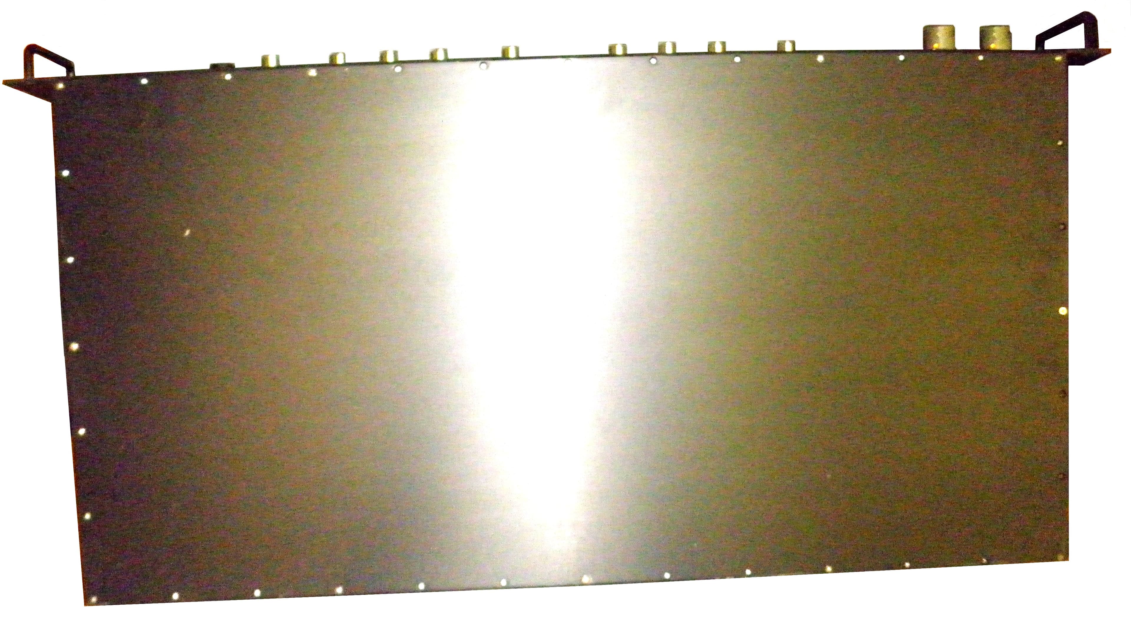
NVRCSIDRACELAAWS
Aug 23, 2015AWS Repeater
Equipment Class
B2I - Part 20 Industrial Booster (CMRS)
NVRCSICPBHMG-C4
Apr 30, 2013The Co-Pilot Beacon C4
Equipment Class
TNB - Licensed Non-Broadcast Station Transmitter
NVRCSICPBHMG-P4
Apr 28, 2013THE CO-PILOT BEACON P4
Equipment Class
PCB - PCS Licensed Transmitter
NVRCSICPBHMG-AW4
Dec 20, 2012The Co-Pilot Beacon
Equipment Class
TNB - Licensed Non-Broadcast Station Transmitter