NVRCSI-DSP85-1W-PBi-directional Amplifier/Repeater
Westell, Inc.
Click to zoom
Application Details
- Equipment Class
- AMP - Amplifier
- Date of Grant
- Jun 06, 2006
- Application Purpose
- Original Equipment
- Date of Application
- Jun 06, 2006
- Equipment Note
- Bi-directional Amplifier/Repeater
- Frequency Range
- 1930.00000000 - 1990.00000000
- Company
- Westell, Inc.
- Country
- United States
Documents & Files
Document Text
Text extracted from the exhibit documents filed with the FCC. Open a document above to read the original.
Test Report
Test Report No. R-4560N-1 FCC ID: NVRCSI-DSP85-1W-P REPORT OF MEASUREMENTS FOR CELLULAR SPECIALTIES, INC. FREQUENCY PROGRAMMABLE REPEATER MODEL: DSP85-1W-P FCC ID: NVRCSI-DSP85-1W-P Test Report No. R-4560N-1 FCC ID: NVRCSI-DSP85-1W-P CERTIFICATION APPLICATION Applicant/Manufacturer: Cellular Specialties 670 North Commercial Street Manchester, NH 03101 Equipment under Test (EUT): The EUT is a Frequency Programmable Repeater used to amplify cellular signals in the PCS bands. Model: DSP85-1W-P FCC ID Number: FCC ID: NVRCSI-DSP85-1W-P Applicable Test Standard: FCC Parts 2 & 24 Device Classification: Mobile EUT Frequency Range Band 1: Uplink: 1850MHz TO 1910MHz Downlink: 1930MHz TO 1990MHz EUT Gain: Uplink: 78.6dB Downlink: 77.8dB Power Output Rating Based Uplink: +27.2dBm=0.5W on max input single channel Downlink: +26.8dBm=0.5W (For Certification Grant): Modulation Type: CDMA, TDMA, GSM RF Exposure + Antenna Installation: See Attached Installation/Users Manual and MPE Evaluation Power Ratings Per Channel: See Power Per Channel Test Data Measurements Required by FCC: See Report Section 1 (Summary of Test Program) and the following Test Report Data Attachments: -RF Power Output -Intermodulation Characteristics (Two-Tone) -Occupied Bandwidth -Spurious Emissions at Antenna Terminals -Effective Radiated Power of Spurious Radiation -Frequency Stability Test Report No. R-4560N-1 FCC ID: NVRCSI-DSP85-1W-P SECTION 1 SUMMARY OF TEST PROGRAM INTERMODULATION CHARACTERISTICS (TWO TONE) Measurement Procedure: Two signals were injected, in turn, to each uplink and downlink frequency band via a two way power combiner. Testing was performed at both the low band edge and high band edge of each pass band. The output of each signal generator was adjusted so that the two output fundamental frequencies were equal in magnitude. Testing was performed for TDMA, CDMA and GSM Modulation types. At the maximum specified input power levels all intermodulation products were at -13dBm or below for each modulation. See attached test data. OCCUPIED BANDWIDTH Measurement Procedure: For Occupied Bandwidth, measurements were made to compare the input signal to the output signal. The signal generator output was connected to the spectrum analyzer. A TDMA modulation signal was then applied to the carrier. Waveforms were then noted on an X-Y plot. Next, the signal generator was connected to the EUT and the output of the EUT was connected to the spectrum analyzer. The output waveform after amplification was then compared to the original input signal to ensure that no significant differences occured between the input signal and the amplified signal. Testing was performed at two frequencies within each passband (uplink and downlink). See Occupied Bandwidth Data. An explanation of the data is as follows: There are two signals superimposed on each plot, one signal is the waveform before modulation, the other is the modulated carrier. In each case the center of the grid shows a narrowband signal projecting out from the center of the modulation envelope. This signal is actually the stored unmodulated signal. Test Report No. R-4560N-1 FCC ID: NVRCSI-DSP85-1W-P SPURIOUS EMISSIONS AT ANTENNA TERMINALS Measurement Procedure: The signal generator output was connected in turn to the uplink and downlink input ports of the EUT. The input power level was at the maximum level which was ascertained during the Power Output test. A spectrum analyzer was connected to the output of the EUT. The input test frequencies used were three frequencies within each passband (uplink and downlink). The level of any spurious emission was recorded. Testing was performed in the frequency range of 30MHz to 20GHz. Testing was performed for TDMA, CDMA and GSM modulation types. The spurious emissions limit is -13dBm as specified in FCC Part 24. All emissions were below the specified - 13dBm limit. See attached test data. EFFECTIVE RADIATED POWER OF SPURIOUS RADIATION Measurement Procedure: The test sample was placed on a 80cm high wooden test stand which was located 3 meters from the test antenna on an FCC listed test site. A signal generator was connected to the input of the amplifier. The signal generator output was set to provide the input power level necessary to achieve maximum output power of the amplifier at 3 frequencies within each passband (uplink and downlink). The effective radiated power of each out of band spurious emission was measured using the substitution method specified in TIA/EIA-603. The frequency range of the test was 30MHz – 20GHz. The limit for out of band spurious emissions is -13dBm as specified in Part 24. All emissions were below the specified -13dBm limit. See attached test data. RF POWER OUTPUT A signal generator was connected in turn to the uplink and downlink input ports of the test sample. The signal generator was set to maximum input rating and the amplifier was operating at maximum gain. The maximum single channel output power for both the uplink and downlink was measured with a spectrum analyzer connected to the output port. The measured output power was 0.5W for each the uplink and downlink which matched the manufacturer’s rated output power. See attached test data. Test Report No. R-4560N-1 FCC ID: NVRCSI-DSP85-1W-P FREQUENCY STABILITY MEASUREMENTS The test sample was placed into a temperature chamber with AC input power supplied through a variable power source. A signal generator was used to provide the input signal and the output was measured with a frequency counter. With the test sample operating at maximum output power the test sample’s output frequency was measured and recorded at the extremes of the temperature range and at 10 degree increments from -30 degrees C to +50 degrees C while the AC input voltage was varied from 85 to 115% of nominal. The output frequency for both the uplink and the downlink stayed within the assigned frequency band. See attached test data. Test Report No. R-4560N-1 FCC ID: NVRCSI-DSP85-1W-P SECTION…
Text truncated - open the document above for the full version.
Test Report
Customer: Cellular Specialties, Inc. Test Sample: Frequency Programmable Repeater Model Number: DSP85-1W-P Notes: CDMA Modulation Date: April 17, 2006 Tech: T. Hannemann Sheet 1 of 1 Customer: Cellular Specialties, Inc. Test Sample: Frequency Programmable Repeater Model Number: DSP85-1W-P Notes: CDMA Modulation Date: April 17, 2006 Tech: T. Hannemann Sheet 1 of 1 Customer: Cellular Specialties, Inc. Test Sample: Frequency Programmable Repeater Model Number: DSP85-1W-P Notes: CDMA Modulation Date: April 17, 2006 Tech: T. Hannemann Sheet 1 of 1 Customer: Cellular Specialties, Inc. Test Sample: Frequency Programmable Repeater Model Number: DSP85-1W-P Notes: CDMA Modulation Date: April 17, 2006 Tech: T. Hannemann Sheet 1 of 1 Customer: Cellular Specialties, Inc. Test Sample: Frequency Programmable Repeater Model Number: DSP85-1W-P Notes: GSM Modulation Date: April 17, 2006 Tech: T. Hannemann Sheet 1 of 1 Customer: Cellular Specialties, Inc. Test Sample: Frequency Programmable Repeater Model Number: DSP85-1W-P Notes: GSM Modulation Date: April 17, 2006 Tech: T. Hannemann Sheet 1 of 1 Customer: Cellular Specialties, Inc. Test Sample: Frequency Programmable Repeater Model Number: DSP85-1W-P Notes: GSM Modulation Date: April 17, 2006 Tech: T. Hannemann Sheet 1 of 1 Customer: Cellular Specialties, Inc. Test Sample: Frequency Programmable Repeater Model Number: DSP85-1W-P Notes: GSM Modulation Date: April 17, 2006 Tech: T. Hannemann Sheet 1 of 1 Customer: Cellular Specialties, Inc. Test Sample: Frequency Programmable Repeater Model Number: DSP85-1W-P Notes: TDMA Modulation Date: April 17, 2006 Tech: T. Hannemann Sheet 1 of 1 Customer: Cellular Specialties, Inc. Test Sample: Frequency Programmable Repeater Model Number: DSP85-1W-P Notes: TDMA Modulation Date: April 17, 2006 Tech: T. Hannemann Sheet 1 of 1 Customer: Cellular Specialties, Inc. Test Sample: Frequency Programmable Repeater Model Number: DSP85-1W-P Notes: TDMA Modulation Date: April 17, 2006 Tech: T. Hannemann Sheet 1 of 1 Customer: Cellular Specialties, Inc. Test Sample: Frequency Programmable Repeater Model Number: DSP85-1W-P Notes: TDMA Modulation Date: April 17, 2006 Tech: T. Hannemann Sheet 1 of 1 Customer: Cellular Specialties, Inc. Test Sample: Frequency Programmable Repeater Model Number: DSP85-1W-P Notes: CDMA Modulation Date: April 17, 2006 Tech: T. Hannemann Sheet 1 of 1 Customer: Cellular Specialties, Inc. Test Sample: Frequency Programmable Repeater Model Number: DSP85-1W-P Notes: CDMA Modulation Date: April 17, 2006 Tech: T. Hannemann Sheet 1 of 1 Customer: Cellular Specialties, Inc. Test Sample: Frequency Programmable Repeater Model Number: DSP85-1W-P Notes: TDMA Modulation Date: April 17, 2006 Tech: T. Hannemann Sheet 1 of 1 Customer: Cellular Specialties, Inc. Test Sample: Frequency Programmable Repeater Model Number: DSP85-1W-P Notes: TDMA Modulation Date: April 17, 2006 Tech: T. Hannemann Sheet 1 of 1 Customer: Cellular Specialties, Inc. Test Sample: Frequency Programmable Repeater Model Number: DSP85-1W-P Notes: TDMA Modulation Date: April 17, 2006 Tech: T. Hannemann Sheet 1 of 1 Customer: Cellular Specialties, Inc. Test Sample: Frequency Programmable Repeater Model Number: DSP85-1W-P Notes: TDMA Modulation Date: April 17, 2006 Tech: T. Hannemann Sheet 1 of 1 Customer: Cellular Specialties, Inc. Test Sample: Frequency Programmable Repeater Model Number: DSP85-1W-P Notes: GSM Modulation Date: April 17, 2006 Tech: T. Hannemann Sheet 1 of 1 Customer: Cellular Specialties, Inc. Test Sample: Frequency Programmable Repeater Model Number: DSP85-1W-P Notes: GSM Modulation Date: April 17, 2006 Tech: T. Hannemann Sheet 1 of 1 Customer: Cellular Specialties, Inc. Test Sample: Frequency Programmable Repeater Model Number: DSP85-1W-P Notes: GSM Modulation Date: April 17, 2006 Tech: T. Hannemann Sheet 1 of 1 Customer: Cellular Specialties, Inc. Test Sample: Frequency Programmable Repeater Model Number: DSP85-1W-P Notes: GSM Modulation Date: April 17, 2006 Tech: T. Hannemann Sheet 1 of 1 Customer: Cellular Specialties, Inc. Test Sample: Frequency Programmable Repeater Model Number: DSP85-1W-P Notes: CDMA Modulation Date: April 17, 2006 Tech: T. Hannemann Sheet 1 of 1 Customer: Cellular Specialties, Inc. Test Sample: Frequency Programmable Repeater Model Number: DSP85-1W-P Notes: CDMA Modulation Date: April 17, 2006 Tech: T. Hannemann Sheet 1 of 1 Customer: Cellular Specialties, Inc. Test Sample: Frequency Programmable Repeater Model Number: DSP85-1W-P Notes: CDMA Modulation Date: April 17, 2006 Tech: T. Hannemann Sheet 1 of 1 Customer: Cellular Specialties, Inc. Test Sample: Frequency Programmable Repeater Model Number: DSP85-1W-P Notes: CDMA Modulation Date: April 17, 2006 Tech: T. Hannemann Sheet 1 of 1 Customer: Cellular Specialties, Inc. Test Sample: Frequency Programmable Repeater Model Number: DSP85-1W-P Notes: GSM Modulation Date: April 17, 2006 Tech: T. Hannemann Sheet 1 of 1 Customer: Cellular Specialties, Inc. Test Sample: Frequency Programmable Repeater Model Number: DSP85-1W-P Notes: GSM Modulation Date: April 17, 2006 Tech: T. Hannemann Sheet 1 of 1 Customer: Cellular Specialties, Inc. Test Sample: Frequency Programmable Repeater Model Number: DSP85-1W-P Notes: GSM Modulation Date: April 17, 2006 Tech: T. Hannemann Sheet 1 of 1 Customer: Cellular Specialties, Inc. Test Sample: Frequency Programmable Repeater Model Number: DSP85-1W-P Notes: GSM Modulation Date: April 17, 2006 Tech: T. Hannemann Sheet 1 of 1 Customer: Cellular Specialties, Inc. Test Sample: Frequency Programmable Repeater Model Number: DSP85-1W-P Notes: TDMA Modulation Date: April 17, 2006 Tech: T. Hannemann Sheet 1 of 1 Customer: Cellular Specialties, Inc. Test Sample: Frequency Programmable Repeater Model Number: DSP85-1W-P Notes: TDMA Modulation Date: April 17, 2006 Tech: T. Hannemann Sheet 1 of 1 Customer: Cellular Specialties, Inc. Test Sample: Frequency Programmable Repeater Model Number: DSP85-1W-P Notes: TDMA Modulation Date: April 17, 2006 Tech:…
Text truncated - open the document above for the full version.
Contact Information
Applicant
Joseph K Gage(Compliance Engineer)
Technical Contact
Retlif Testing LaaboratoriesScott Wentworth
[email protected]603-497-4600
101 New Boston Road · Goffstown, New Hampshire · United States
Non-Technical Contact
Retlif Testing LaaboratoriesScott Wentworth
[email protected]603-497-4600
Test Firm
Retlif Testing LaboratoriesScott Wentworth
Technical Specifications
| # | Rule Parts | Frequency Range | Power Output | Emission | Tolerance |
|---|---|---|---|---|---|
| 6 | 24 | 1.93 GHz - 1.99 GHz | 500.00 mW | DXW | Amp |
Other Applications from Westell, Inc.

NVRDPSA81090-78
Jan 25, 2021700/800 MHZ DUAL BAND INDUSTRIAL BOOSTER
Equipment Class
B2I - Part 20 Industrial Booster (CMRS)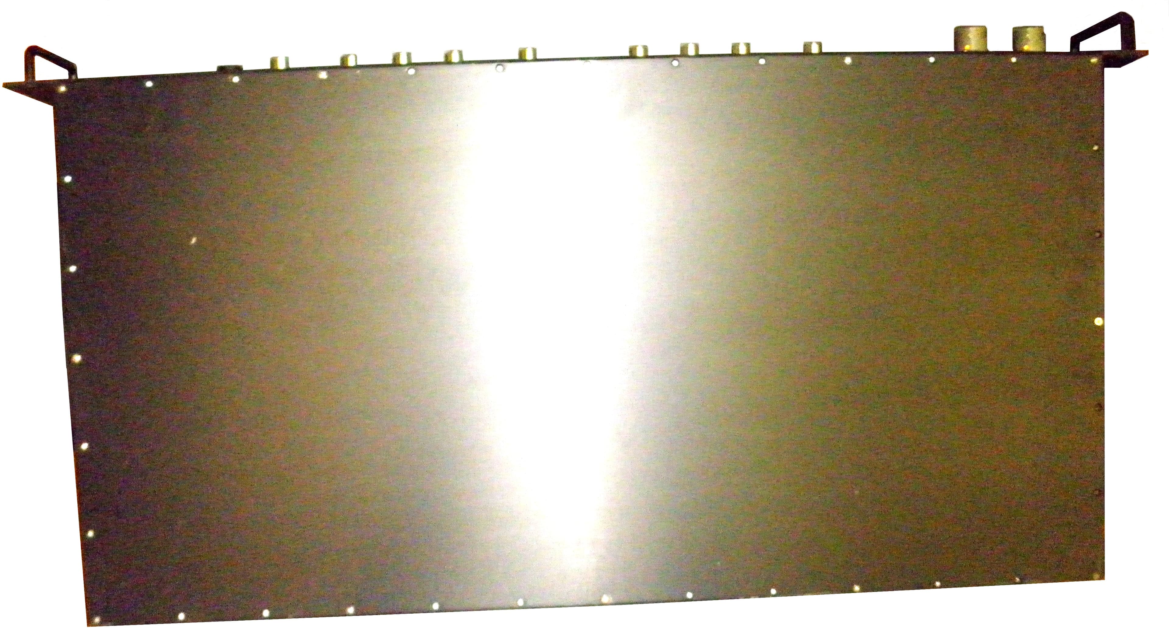
NVRCSIDRACELAAWS
Aug 23, 2015AWS Repeater
Equipment Class
B2I - Part 20 Industrial Booster (CMRS)
NVRCSICPBHMG-C4
Apr 30, 2013The Co-Pilot Beacon C4
Equipment Class
TNB - Licensed Non-Broadcast Station Transmitter
NVRCSICPBHMG-P4
Apr 28, 2013THE CO-PILOT BEACON P4
Equipment Class
PCB - PCS Licensed Transmitter
NVRCSICPBHMG-AW4
Dec 20, 2012The Co-Pilot Beacon
Equipment Class
TNB - Licensed Non-Broadcast Station Transmitter