NVRCSI-DSP85-1W-SDigital Repeater
Westell, Inc.
Click to zoom
Application Details
- Equipment Class
- TNB - Licensed Non-Broadcast Station Transmitter
- Date of Grant
- Feb 01, 2007
- Application Purpose
- Original Equipment
- Date of Application
- Feb 01, 2007
- Equipment Note
- Digital Repeater
- Frequency Range
- 851.00000000 - 869.00000000
- Company
- Westell, Inc.
- Country
- United States
Documents & Files
Document Text
Text extracted from the exhibit documents filed with the FCC. Open a document above to read the original.
Users Manual
Rev 009C REVISED DOCUMENT 2/1/2007 1 CSI Wireless Engine Digital Repeater OPERATIONAL MANUAL Rev 009C REVISED DOCUMENT 2/1/2007 2 Table Of Contents Product Registration/Certification Information ............... 1 Safety Guidelines.......................................................... 1 Product Description ....................................................... 2-4 LED Indicators .................................................. 3 Local Communication Interface Ports............ 3 Pin-out Chart..................................................... 4 Installation...................................................................... 6 Important Safety Information ......................................... 7 Circuit Description................................................ 7-12 Block Diagram.......................................... 9 Specifications............................................10-11 Mechanical Drawings..................................12-13 Performance Adjustment ............................................... 13-27 View Menu Series............................................. 14 View Menu Flow Diagram................................. 17 Configuration Menu Series ............................... 18 Configuration Flow Diagram ............................. 21-27 Troubleshooting ............................................................. 28 Product Warranty........................................................... 29 FCC Information.................................................. 29 Appendix A (Error & Control Messages) ...................30 Appendix B (Interconnect Information) ......................31-32 Product Warranty........................................................... 41 Rev 009C REVISED DOCUMENT 2/1/2007 3 Product Certification/Registration Information The serial number may be found on the label on the rear panel of the unit. For your convenience, note this number below. Retain this manual, along with proof of purchase, to serve as a permanent record of your purchase for future reference or in the event of theft. MODEL NUMBER...................................................................SERIAL NUMBER DATE OF PURCHASE ...........................................................POINT OF SALE COMPANY DISCLAIMER: All information and statements contained herein are accurate to the best of the knowledge of Cellular Specialties, Inc. (CSI), but Cellular Specialties makes no warranty with respect thereto, including without limitation any results that may be obtained from the products described herein or the infringement by such products of any proprietary rights of any persons. Use or application of such information or statements is at the users sole risk, without any liability on the part of Cellular Specialties, Inc. Nothing herein shall be construed as license or recommendation for use, which infringes upon any proprietary rights of any person. Product material and specifications are subject to change without notice. Cellular Specialties’ standard terms of sale and the specific terms of any particular sale apply. Document Purpose The purpose of this document is to provide a step-by step procedure to install and commision a Digital Repeater System. Following the procedures outlined below will minimize risks associated with modifying a live system and preclude service interuptions. Application This guide should be applied whenever a need exists to add Digital Repeater capability to an existing system or when this capability is being added simultaneously with a new installation. Safety Guidelines The general safety information in this guideline applies to both operating and service personnel. Specific warnings and cautions will be found in other parts of this manual where they apply, but may not appear in this summary. Failure to comply with these precautions or specific warnings elsewhere in the manual violates safety standards of design, manufacture, and intended use of equipment. Cellular Specialties, Inc. assumes no liability for the customer’s failure to comply with these requirements: Grounding This amplifier system is designed to operate from 120 VAC @ 3.5A max current and should always be operated with the ground wire properly connected. Do not remove or otherwise alter the grounding lug on the power cord. Explosive Atmospheres This product has an integral circuit breaker, which may cause an electrical flash if the breaker should reset. To avoid explosion or fire, do not operate this product in the presence of flammable gases or fumes. Lightning Danger Do not install or make adjustments to this unit during an electrical storm. No User Serviceable Parts Inside HAZARDOUS VOLTAGES ARE PRESENT WHEN THE COVER IS REMOVED. Opening the chassis will void your warranty. If you suspect a malfunction with this product, call your dealer or the Cellular Specialties Support Line at (603) 626-6677. Rev 009C REVISED DOCUMENT 2/1/2007 4 Product Description Cellular Specialties, Inc. (CSI) developed the Wireless Engine Digital Repeater for use within enclosed structures where sufficient signal from local cell sites to operate cell phones is unavailable. Adequate signal must be available outside the structure as a prerequisite to achieving in-building coverage. The Digital Repeater is connected to an external antenna, usually on the roof, and to one or more internal antennas placed strategically throughout the area where wireless services are desired. The external antenna typically is a directional type such as a “yagi”. Internal antennas are typically omni-directional, although various other types may be used depending on the coverage application. The Frequency Agile Repeater (FAR) amplifies both the “Uplink” (phone to tower) & “Downlink”(tower to phone) signals thus facilitating communications to and from the intended wireless infrastructure. There are seven amplification stages on either the downlink or the uplink creating a total of +85 dB nominal gain on each link. Ga…
Text truncated - open the document above for the full version.
ID Label/Location Info
MODEL DSP85-1W-S Frequency Programmable Repeater FCC ID LABEL FCC ID NVRCSI-DSP85-1W-S IC: 4307A-DSP85-1W-S This device complies with parts 90 and 2 of the FCC rules and with Industry Canada specification RSS-131
Parts List/Tune Up Info
December 7, 2006 Mr. Scott Wentworth Retlif Laboratories 101 New Boston Rd. Goffstown, NH 03045 Re: Adjustment of the Model DSP85-1W-S In-building Amplifier in the Field The CSI Model DSP85-1W-S In-Building Amplifier offers only adjustment of gain (below its factory-set maximum gain level) to the technician during installation and maintenance activities. This adjustment is dependent on the physical environment in which the amplifier is to be installed and is described in the Installation and Users Manual. This is the only adjustment accessible without opening the amplifier. Frequency response and gain thresholds are factory set and in no circumstance are they to be adjusted in the field. Regards, Burt Salkins Burt Salkins Director of Engineering
RF Exposure Info
MPE Compliance-DSP85-S-Rev-2-yagi.doc 1 Evaluation of the CSI Model DSP85-1W-S Frequency Programmable Repeater For Compliance with FCC Guidelines For Human Exposure to Radio Frequency Electromagnetic Fields 7 December 2006 MPE Compliance-DSP85-S-Rev-2-yagi.doc 2 General The CSI Model DSP85-1W-S Repeater is considered to be a “mobile” device operating in the Cellular Service authorized under part 90. As such, the equipment is required to be evaluated for RF exposure if operated below 1.5 GHz with an effective radiated power (ERP) of 1.5 watts or more, as defined in 2.1091 of FCC rules. Downlink For the downlink portion of the Model DSP85-1W-S, the maximum rated output power is +30dBm (1000 mW). As stated in the Model DSP85-1W-S Manual, the maximum authorized antenna gain is 3 dBi, corresponding to an Omni-Directional antenna. Neglecting cable losses, the worst-case EIRP will be 2.0 watts or an ERP of 1.22 watts, (ERP=EIRP/1.64). This is well below the 3.0 watts ERP limit and therefore excludes the downlink from routine evaluation. The Cautions in the Model DSP85-1W-S manual clearly define the antenna selection and installation criteria in order to maintain a minimum 20-centimeter separation. Uplink For the uplink portion of the Model DSP85-1W-S, the maximum rated output power is +30dBm (1000 mW). As stated in the Model DSP85-1W-S Manual, the maximum authorized antenna gain is 14 dBi, corresponding to a Multi Element Yagi-Directional or Corner Reflector antenna. Neglecting cable losses, the worst-case EIRP will be 25.1 watts or an ERP of 15.3 watts. Under these conditions the unit must be evaluated for minimum separation distances in order to comply with the exposure limits of 1.1310 of the FCC rules. Using the guidelines in FCC OET Bulletin 65 and Supplement C, the power density at a reasonable distance from the maximum gain antenna was calculated. The minimum safe distance was also determined based on the uncontrolled exposure limits defined in Table 1B of FCC rules 1.1311. The following assumptions are made concerning these calculations: Po = 1000 mw average Cable Loss = 0 dB Ant Gain = 11.8 dBd (14 dBi) Frequency = 806-824 MHz Main Beam (worst-case) Rooftop 100% reflection Reasonable Distance = 4 feet (120 cm) MPE Compliance-DSP85-S-Rev-2-yagi.doc 3 Therefore, from OET Bulletin 65, S = (PG)/4πR 2 or S = EIRP/4πR 2 For 100% reflection, a doubling of the field strength can be expected. The above equation can be modified to, S = (2) 2 PG/4πR 2 = EIRP/πR 2 Solving for S at a distance of 4 feet (120 cm) gives, S = (1000) (25)/ π (120) 2 = 0.55 mw/cm 2 From FCC rules 1.1311, Table 1B, the allowable limit for uncontrolled exposure is f(MHz)/1500 mw/cm 2 in the frequency range of 300 to 1500 MHz. At 815 MHz this corresponds to 0.55 mw/cm 2 . The calculated value of 0.55 is equal to the limit of 0.55 thereby showing compliance under worst-case operating conditions. As in the case of the downlink, the Cautions in the Model DSP85-1W-S manual clearly define the antenna selection and installation criteria in order to maintain a minimum 4- foot separation.
Test Report
Test Report No. R-4733N-1 FCC ID: NVRCSI-DSP85-1W-S REPORT OF MEASUREMENTS FOR CELLULAR SPECIALTIES, INC. DIGITAL REPEATER MODEL: CSI-DSP-SMR-800 FCC ID: NVRCSI-DSP85-1W-S Test Report No. R-4733N-1 FCC ID: NVRCSI-DSP85-1W-S CERTIFICATION APPLICATION Applicant/Manufacturer: Cellular Specialties 670 North Commercial Street Manchester, NH 03101 Equipment under Test (EUT): The EUT is a Digital Repeater used to amplify signals in the SMR band. Model: CSI-DSP-SMR-800 FCC ID Number: FCC ID: NVRCSI-DSP85-1W-S Applicable Test Standard: FCC Parts 2 & 90 Device Classification: Mobile EUT Frequency Range Band 1: Uplink: 806MHz TO 824MHz Downlink: 851MHz TO 869MHz EUT Gain: Uplink: 84.6dB Downlink: 87.4dB Power Output Rating Based Uplink: +28.6dBm = .724W on max input single channel Downlink: +29.4dBm = .871W (For Certification Grant): Modulation Type: TDMA RF Exposure + Antenna Installation: See Attached Installation/Users Manual and MPE Evaluation Power Ratings Per Channel: See Power Per Channel Test Data Measurements Required by FCC: See Report Section 1 (Summary of Test Program) and the following Test Report Data Attachments: -RF Power Output -Intermodulation Characteristics (Two-Tone) -Occupied Bandwidth -Spurious Emissions at Antenna Terminals -Effective Radiated Power of Spurious Radiation -Frequency Stability Test Report No. R-4733N-1 FCC ID: NVRCSI-DSP85-1W-S SECTION 1 SUMMARY OF TEST PROGRAM INTERMODULATION CHARACTERISTICS (TWO TONE) Measurement Procedure: Two signals were injected, in turn, to each uplink and downlink frequency band via a two way power combiner. Testing was performed at both the low band edge and high band edge of each pass band. The output of each signal generator was adjusted so that the two output fundamental frequencies were equal in magnitude. Testing was performed for TDMA Modulation type. At the maximum specified input power levels all intermodulation products were at -13dBm or below for each modulation. See attached test data. OCCUPIED BANDWIDTH Measurement Procedure: For Occupied Bandwidth, measurements were made to compare the input signal to the output signal. The signal generator output was connected to the spectrum analyzer. A TDMA modulation signal was then applied to the carrier. Waveforms were then noted on an X-Y plot. Next, the signal generator was connected to the EUT and the output of the EUT was connected to the spectrum analyzer. The output waveform after amplification was then compared to the original input signal to ensure that no significant differences occurred between the input signal and the amplified signal. Testing was performed at one frequency within each passband (uplink and downlink). See Occupied Bandwidth Data. An explanation of the data is as follows: There are two signals superimposed on each plot, one signal is the waveform before modulation, the other is the modulated carrier. In each case the center of the grid shows a narrowband signal projecting out from the center of the modulation envelope. This signal is actually the stored unmodulated signal. Test Report No. R-4733N-1 FCC ID: NVRCSI-DSP85-1W-S SPURIOUS EMISSIONS AT ANTENNA TERMINALS Measurement Procedure: The signal generator output was connected in turn to the uplink and downlink input ports of the EUT. The input power level was at the maximum level which was ascertained during the Power Output test. A spectrum analyzer was connected to the output of the EUT. The input test frequencies used were three frequencies within each passband (uplink and downlink). The level of any spurious emission was recorded. Testing was performed in the frequency range of 30MHz to 9GHz. Testing was performed for TDMA modulation types. The spurious emissions limit is - 13dBm as specified in FCC Part 90. All emissions were below the specified -13dBm limit. See attached test data. EFFECTIVE RADIATED POWER OF SPURIOUS RADIATION Measurement Procedure: The test sample was placed on a 80cm high wooden test stand which was located 3 meters from the test antenna on an FCC listed test site. A signal generator was connected to the input of the amplifier. The signal generator output was set to provide the input power level necessary to achieve maximum output power of the amplifier at 3 frequencies within each passband (uplink and downlink). The effective radiated power of each out of band spurious emission was measured using the substitution method specified in TIA/EIA-603. The frequency range of the test was 30MHz – 9GHz. The limit for out of band spurious emissions is -13dBm as specified in Part 90. All emissions were below the specified -13dBm limit. See attached test data. RF POWER OUTPUT A signal generator was connected in turn to the uplink and downlink input ports of the test sample. The signal generator was set to maximum input rating and the amplifier was operating at maximum gain. The maximum single channel output power for both the uplink and downlink was measured with a spectrum analyzer connected to the output port. The measured output power was 0.724W for the uplink and 0.871W for the downlink which matched the manufacturer’s rated output power. See attached test data. Test Report No. R-4733N-1 FCC ID: NVRCSI-DSP85-1W-S FREQUENCY STABILITY MEASUREMENTS The test sample was placed into a temperature chamber with AC input power supplied through a variable power source. A signal generator was used to provide the input signal and the output was measured with a frequency counter. With the test sample operating at maximum output power the test sample’s output frequency was measured and recorded at the extremes of the temperature range and at 10 degree increments from -30 degrees C to +50 degrees C while the AC input voltage was varied from 85 to 115% of nominal. The output frequency for both the uplink and the downlink stayed within the assigned frequency band. See attached test data. Test Method:Customer: Test Sample: Job No: R-4733N-1 Model No: Serial No: Technician: M.Seamans Test Specification: Pa…
Text truncated - open the document above for the full version.
Contact Information
Applicant
Joseph K Gage(Compliance Engineer)
Technical Contact
Retlif Testing LaboratoriesScott Wentworth
[email protected]603-497-4600
101 New Boston Road · Goffstown, New Hampshire · United States
Non-Technical Contact
Retlif Testing LaboratoriesScott Wentworth
[email protected]603-497-4600
Technical Specifications
| # | Rule Parts | Frequency Range | Power Output | Emission | Tolerance |
|---|---|---|---|---|---|
| 2 | 9 | 851 MHz - 869 MHz | 871.00 mW | DXW | Amp |
Other Applications from Westell, Inc.

NVRDPSA81090-78
Jan 25, 2021700/800 MHZ DUAL BAND INDUSTRIAL BOOSTER
Equipment Class
B2I - Part 20 Industrial Booster (CMRS)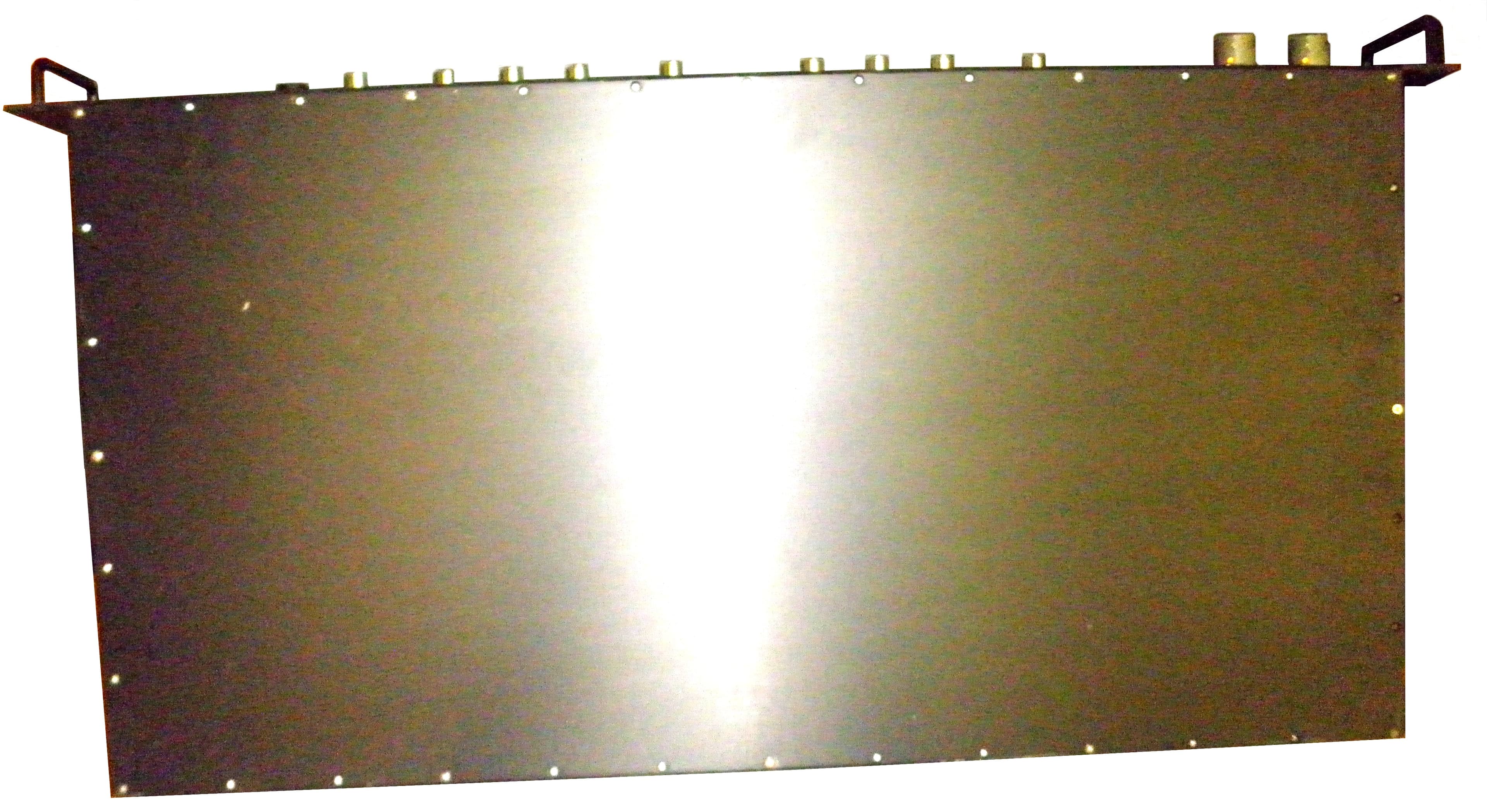
NVRCSIDRACELAAWS
Aug 23, 2015AWS Repeater
Equipment Class
B2I - Part 20 Industrial Booster (CMRS)
NVRCSICPBHMG-C4
Apr 30, 2013The Co-Pilot Beacon C4
Equipment Class
TNB - Licensed Non-Broadcast Station Transmitter
NVRCSICPBHMG-P4
Apr 28, 2013THE CO-PILOT BEACON P4
Equipment Class
PCB - PCS Licensed Transmitter
NVRCSICPBHMG-AW4
Dec 20, 2012The Co-Pilot Beacon
Equipment Class
TNB - Licensed Non-Broadcast Station Transmitter