NVRCSI110-03Amplifier
Westell, Inc.
Click to zoom
Application Details
- Equipment Class
- AMP - Amplifier
- Date of Grant
- Mar 30, 2000
- Application Purpose
- Original Equipment
- Date of Application
- Feb 11, 2000
- Equipment Note
- Amplifier
- Frequency Range
- 824.00000000 - 849.00000000
- Company
- Westell, Inc.
- Country
- United States
Documents & Files
Document Text
Text extracted from the exhibit documents filed with the FCC. Open a document above to read the original.
Users Manual
Note: This report may not be duplicated without prior written consent of Bay Area Compliance Laboratory Corporation. This report must not be used by the client to claim product endorsement by NVLAP or any agency of the U.S. Government. FCC PART 22 TYPE APPROVAL EUT USER MANUAL FOR CELLULAR SPECIALTIES, INC. 670 N. Commercial St. Manchester NH 03101 FCC ID: NVRCSI110-03 February 4, 2000 This Report Concerns: Original Report Equipment Type: Amplifier Test Engineer:John Chan Test Date:January 26, 2000 Reviewed By: John Y. Chan – Engineering Manager Prepared By:Bay Area Compliance Laboratory Corporation 230 Commercial Street, Suite 2 Sunnyvale, CA 94086 (408) 732-9162 Cellular Specialties, Inc. FCC ID: NVRCSI110-03 Report # EUT User manual.docFCC Part 22 Type Approval report Page 2 of 25 TABLE OF CONTENTS 1 - GENERAL INFORMATION.................................................................................................................................3 1.1 PRODUCT DESCRIPTION FOR EQUIPMENT UNDER TEST (EUT)..............................................................................3 1.2 OBJECTIVE............................................................................................................................................................3 1.3 RELATED SUBMITTAL(S)/GRANT(S)......................................................................................................................3 1.4 TEST METHODOLOGY............................................................................................................................................3 1.5 TEST FACILITY......................................................................................................................................................4 1.6 TEST EQUIPMENT LIST..........................................................................................................................................4 1.7 EQUIPMENT UNDER TEST (EUT)...........................................................................................................................5 1.8 SUPPORT EQUIPMENT............................................................................................................................................5 1.9 EUT CONFIGURATION DETAILS AND LIST............................................................................................................5 1.10 EXTERNAL I/O CABLING.....................................................................................................................................5 2 - SYSTEM TEST CONFIGURATION....................................................................................................................6 2.1 JUSTIFICATION......................................................................................................................................................6 2.2 BLOCK DIAGRAM..................................................................................................................................................6 2.3 TEST SETUP BLOCK DIAGRAM..............................................................................................................................7 2.4 EQUIPMENT MODIFICATIONS................................................................................................................................8 APPENDIX A – AGENCY AUTHORIZATION LETTER.....................................................................................9 APPENDIX B – EUT SCHEMATICS AND BLOCKDIAGRAM.........................................................................11 Cellular Specialties, Inc. FCC ID: NVRCSI110-03 Report # EUT User manual.docFCC Part 22 Type Approval report Page 3 of 25 1 - GENERAL INFORMATION 1.1 Product Description for Equipment Under Test (EUT) The Cellular Specialties, Inc., FCC ID NVRCSI110-03 (AMPLIFIER) or the "EUT" as referred to in this report is a device using in enclosed structures where sufficient signal from local cell sites to operate cell phones was unavailable within the building. The device is connected to an external antenna, usually on the roof, and to one or more internal antennas placed strategically throughout the area where phone service is desired. The EUT measures 10” L x 12” W x 3.5” H. 1.2 Objective This type approval report is prepared on behalf of Cellular Specialties, Inc. in accordance with Part 2, Subpart J, Part 15, Subparts A and B, and Part 22 Subpart H, of the Federal Communication Commissions rules. The objective of the manufacturer is to demonstrate compliance with FCC rules for output power, 20 dB bandwidth, occupied bandwidth, spurious emission at antenna terminal, two-tone test, conducted and radiated margin. 1.3 Related Submittal(s)/Grant(s) No Related Submittals 1.4 Test Methodology All measurements contained in this report were conducted with ANSI C63.4 –1992, American National Standard for Methods of Measurement of Radio-Noise Emissions from Low-Voltage Electrical and Electronic Equipment in the range of 9 kHz to 40 GHz. All radiated and conducted emissions measurement was performed at Bay Area Compliance Laboratory, Corp. The radiated testing was performed at an antenna-to-EUT distance of 3 meters. Cellular Specialties, Inc. FCC ID: NVRCSI110-03 Report # EUT User manual.docFCC Part 22 Type Approval report Page 4 of 25 1.5 Test Facility The Open Area Test site used by Bay Area Compliance Laboratory Corporation to collect radiated and conducted emission measurement data is located in the back parking lot of the building at 230 Commercial Street, Suite 2, Sunnyvale, California, USA. Test sites at Bay Area Compliance Laboratory Corporation has been fully described in reports submitted to the Federal Communication Commission (FCC) and Voluntary Control Council for Interference (VCCI). The details of these reports has been found to be in compliance with the requirements of Section 2.948 of the FCC Rules on February 11 and December 10, 1997 and Article 8 of the VCCI regulations o…
Text truncated - open the document above for the full version.
External Photos
Note: This report may not be duplicated without prior written consent of Bay Area Compliance Laboratory Corporation. This report must not be used by the client to claim product endorsement by NVLAP or any agency of the U.S. Government. FCC PART 22 TYPE APPROVAL EUT EXTERNAL PHOTO FOR CELLULAR SPECIALTIES, INC. 670 N. Commercial St. Manchester NH 03101 FCC ID: NVRCSI110-03 February 4, 2000 This Report Concerns: Original Report Equipment Type: Amplifier Test Engineer:John Chan Test Date:January 26, 2000 Reviewed By: John Y. Chan – Engineering Manager Prepared By:Bay Area Compliance Laboratory Corporation 230 Commercial Street, Suite 2 Sunnyvale, CA 94086 (408) 732-9162 Cellular Specialties, Inc. FCC ID: NVRCSI110-03 Report # EUT External photo.docFCC Part 22 Type Approval report Page 2 of 14 TABLE OF CONTENTS 1 - GENERAL INFORMATION.................................................................................................................................3 1.1 PRODUCT DESCRIPTION FOR EQUIPMENT UNDER TEST (EUT)..............................................................................3 1.2 OBJECTIVE............................................................................................................................................................3 1.3 RELATED SUBMITTAL(S)/GRANT(S)......................................................................................................................3 1.4 TEST METHODOLOGY............................................................................................................................................3 1.5 TEST FACILITY......................................................................................................................................................4 1.6 TEST EQUIPMENT LIST..........................................................................................................................................4 1.7 EQUIPMENT UNDER TEST (EUT)...........................................................................................................................5 1.8 SUPPORT EQUIPMENT............................................................................................................................................5 1.9 EUT CONFIGURATION DETAILS AND LIST............................................................................................................5 1.10 EXTERNAL I/O CABLING.....................................................................................................................................5 2 - SYSTEM TEST CONFIGURATION....................................................................................................................6 2.1 JUSTIFICATION......................................................................................................................................................6 2.2 BLOCK DIAGRAM..................................................................................................................................................6 2.3 TEST SETUP BLOCK DIAGRAM..............................................................................................................................7 2.4 EQUIPMENT MODIFICATIONS................................................................................................................................8 3 – EUT PHOTOGRAPHS..........................................................................................................................................9 3.1 EUT: FRONT VIEW...............................................................................................................................................9 3.2 EUT: REAR VIEW...............................................................................................................................................10 3.3 AC-DC POWER ADAPTER FRONT VIEW..............................................................................................................11 3.4 AC-DC POWER ADAPTER REAR VIEW...............................................................................................................12 APPENDIX A – AGENCY AUTHORIZATION LETTER...................................................................................13 Cellular Specialties, Inc. FCC ID: NVRCSI110-03 Report # EUT External photo.docFCC Part 22 Type Approval report Page 3 of 14 1 - GENERAL INFORMATION 1.1 Product Description for Equipment Under Test (EUT) The Cellular Specialties, Inc., FCC ID NVRCSI110-03 (AMPLIFIER) or the "EUT" as referred to in this report is a device using in enclosed structures where sufficient signal from local cell sites to operate cell phones was unavailable within the building. The device is connected to an external antenna, usually on the roof, and to one or more internal antennas placed strategically throughout the area where phone service is desired. The EUT measures 10” L x 12” W x 3.5” H. 1.2 Objective This type approval report is prepared on behalf of Cellular Specialties, Inc. in accordance with Part 2, Subpart J, Part 15, Subparts A and B, and Part 22 Subpart H, of the Federal Communication Commissions rules. The objective of the manufacturer is to demonstrate compliance with FCC rules for output power, 20 dB bandwidth, occupied bandwidth, spurious emission at antenna terminal, two-tone test, conducted and radiated margin. 1.3 Related Submittal(s)/Grant(s) No Related Submittals 1.4 Test Methodology All measurements contained in this report were conducted with ANSI C63.4 –1992, American National Standard for Methods of Measurement of Radio-Noise Emissions from Low-Voltage Electrical and Electronic Equipment in the range of 9 kHz to 40 GHz. All radiated and conducted emissions measurement was performed at Bay Area Compliance Laboratory, Corp. The radiated testing was performed at an antenna-to-EUT distance of 3 meters. Cellular Specialties, Inc. FCC ID: NVRCSI110-03 Report # EUT External photo.docFCC Part 22 Type Approval report Page 4 o…
Text truncated - open the document above for the full version.
ID Label/Location Info
Note: This report may not be duplicated without prior written consent of Bay Area Compliance Laboratory Corporation. This report must not be used by the client to claim product endorsement by NVLAP or any agency of the U.S. Government. FCC PART 22 TYPE APPROVAL EUT FCC ID LABEL LOCATION FOR CELLULAR SPECIALTIES, INC. 670 N. Commercial St. Manchester NH 03101 FCC ID: NVRCSI110-03 February 4, 2000 This Report Concerns: Original Report Equipment Type: Amplifier Test Engineer:John Chan Test Date:January 26, 2000 Reviewed By: John Y. Chan – Engineering Manager Prepared By:Bay Area Compliance Laboratory Corporation 230 Commercial Street, Suite 2 Sunnyvale, CA 94086 (408) 732-9162 Cellular Specialties, Inc. FCC ID: NVRCSI110-03 Report # FCC ID Label Location.docFCC Part 22 Type Approval report Page 2 of 11 TABLE OF CONTENTS 1 - GENERAL INFORMATION.................................................................................................................................3 1.1 PRODUCT DESCRIPTION FOR EQUIPMENT UNDER TEST (EUT)..............................................................................3 1.2 OBJECTIVE............................................................................................................................................................3 1.3 RELATED SUBMITTAL(S)/GRANT(S)......................................................................................................................3 1.4 TEST METHODOLOGY............................................................................................................................................3 1.5 TEST FACILITY......................................................................................................................................................4 1.6 TEST EQUIPMENT LIST..........................................................................................................................................4 1.7 EQUIPMENT UNDER TEST (EUT)...........................................................................................................................5 1.8 SUPPORT EQUIPMENT............................................................................................................................................5 1.9 EUT CONFIGURATION DETAILS AND LIST............................................................................................................5 1.10 EXTERNAL I/O CABLING.....................................................................................................................................5 2 - SYSTEM TEST CONFIGURATION....................................................................................................................6 2.1 JUSTIFICATION......................................................................................................................................................6 2.2 BLOCK DIAGRAM..................................................................................................................................................6 2.3 TEST SETUP BLOCK DIAGRAM..............................................................................................................................7 2.4 EQUIPMENT MODIFICATIONS................................................................................................................................8 3 – FCC PRODUCT LABELING AND WARNING STATEMENT.......................................................................9 3.1 FCC ID LABEL.....................................................................................................................................................9 3.2 PROPOSED LABEL LOCATION ON EUT..................................................................................................................9 3.3 FCC WARNING STATEMENT.................................................................................................................................9 APPENDIX A – AGENCY AUTHORIZATION LETTER...................................................................................10 Cellular Specialties, Inc. FCC ID: NVRCSI110-03 Report # FCC ID Label Location.docFCC Part 22 Type Approval report Page 3 of 11 1 - GENERAL INFORMATION 1.1 Product Description for Equipment Under Test (EUT) The Cellular Specialties, Inc., FCC ID NVRCSI110-03 (AMPLIFIER) or the "EUT" as referred to in this report is a device using in enclosed structures where sufficient signal from local cell sites to operate cell phones was unavailable within the building. The device is connected to an external antenna, usually on the roof, and to one or more internal antennas placed strategically throughout the area where phone service is desired. The EUT measures 10” L x 12” W x 3.5” H. 1.2 Objective This type approval report is prepared on behalf of Cellular Specialties, Inc. in accordance with Part 2, Subpart J, Part 15, Subparts A and B, and Part 22 Subpart H, of the Federal Communication Commissions rules. The objective of the manufacturer is to demonstrate compliance with FCC rules for output power, 20 dB bandwidth, occupied bandwidth, spurious emission at antenna terminal, two-tone test, conducted and radiated margin. 1.3 Related Submittal(s)/Grant(s) No Related Submittals 1.4 Test Methodology All measurements contained in this report were conducted with ANSI C63.4 –1992, American National Standard for Methods of Measurement of Radio-Noise Emissions from Low-Voltage Electrical and Electronic Equipment in the range of 9 kHz to 40 GHz. All radiated and conducted emissions measurement was performed at Bay Area Compliance Laboratory, Corp. The radiated testing was performed at an antenna-to-EUT distance of 3 meters. Cellular Specialties, Inc. FCC ID: NVRCSI110-03 Report # FCC ID Label Location.docFCC Part 22 Type Approval report Page 4 of 11 1.5 Test Facility The Open Area Test site used by Bay Area Compliance Laboratory Corporation to collect radiated and conducted emission measurement data is located in t…
Text truncated - open the document above for the full version.
Internal Photos
Note: This report may not be duplicated without prior written consent of Bay Area Compliance Laboratory Corporation. This report must not be used by the client to claim product endorsement by NVLAP or any agency of the U.S. Government. FCC PART 22 TYPE APPROVAL EUT INTERNAL PHOTO FOR CELLULAR SPECIALTIES, INC. 670 N. Commercial St. Manchester NH 03101 FCC ID: NVRCSI110-03 February 4, 2000 This Report Concerns: Original Report Equipment Type: Amplifier Test Engineer:John Chan Test Date:January 26, 2000 Reviewed By: John Y. Chan – Engineering Manager Prepared By:Bay Area Compliance Laboratory Corporation 230 Commercial Street, Suite 2 Sunnyvale, CA 94086 (408) 732-9162 Cellular Specialties, Inc. FCC ID: NVRCSI110-03 Report # EUT Internal Photo.docFCC Part 22 Type Approval report Page 2 of 12 TABLE OF CONTENTS 1 - GENERAL INFORMATION.................................................................................................................................3 1.1 PRODUCT DESCRIPTION FOR EQUIPMENT UNDER TEST (EUT)..............................................................................3 1.2 OBJECTIVE............................................................................................................................................................3 1.3 RELATED SUBMITTAL(S)/GRANT(S)......................................................................................................................3 1.4 TEST METHODOLOGY............................................................................................................................................3 1.5 TEST FACILITY......................................................................................................................................................4 1.6 TEST EQUIPMENT LIST..........................................................................................................................................4 1.7 EQUIPMENT UNDER TEST (EUT)...........................................................................................................................5 1.8 SUPPORT EQUIPMENT............................................................................................................................................5 1.9 EUT CONFIGURATION DETAILS AND LIST............................................................................................................5 1.10 EXTERNAL I/O CABLING.....................................................................................................................................5 2 - SYSTEM TEST CONFIGURATION....................................................................................................................6 2.1 JUSTIFICATION......................................................................................................................................................6 2.2 BLOCK DIAGRAM..................................................................................................................................................6 2.3 TEST SETUP BLOCK DIAGRAM..............................................................................................................................7 2.4 EQUIPMENT MODIFICATIONS................................................................................................................................8 5 – FCC PRODUCT LABELING AND WARNING STATEMENT.......................................................................9 5.1 FCC ID LABEL.....................................................................................................................................................9 5.2 PROPOSED LABEL LOCATION ON EUT..................................................................................................................9 5.3 FCC WARNING STATEMENT.................................................................................................................................9 3 – EUT PHOTOGRAPHS........................................................................................................................................10 3.1 EUT: ENCLOSURE OFF VIEW..............................................................................................................................10 APPENDIX A – AGENCY AUTHORIZATION LETTER...................................................................................11 Cellular Specialties, Inc. FCC ID: NVRCSI110-03 Report # EUT Internal Photo.docFCC Part 22 Type Approval report Page 3 of 12 1 - GENERAL INFORMATION 1.1 Product Description for Equipment Under Test (EUT) The Cellular Specialties, Inc., FCC ID NVRCSI110-03 (AMPLIFIER) or the "EUT" as referred to in this report is a device using in enclosed structures where sufficient signal from local cell sites to operate cell phones was unavailable within the building. The device is connected to an external antenna, usually on the roof, and to one or more internal antennas placed strategically throughout the area where phone service is desired. The EUT measures 10” L x 12” W x 3.5” H. 1.2 Objective This type approval report is prepared on behalf of Cellular Specialties, Inc. in accordance with Part 2, Subpart J, Part 15, Subparts A and B, and Part 22 Subpart H, of the Federal Communication Commissions rules. The objective of the manufacturer is to demonstrate compliance with FCC rules for output power, 20 dB bandwidth, occupied bandwidth, spurious emission at antenna terminal, two-tone test, conducted and radiated margin. 1.3 Related Submittal(s)/Grant(s) No Related Submittals 1.4 Test Methodology All measurements contained in this report were conducted with ANSI C63.4 –1992, American National Standard for Methods of Measurement of Radio-Noise Emissions from Low-Voltage Electrical and Electronic Equipment in the range of 9 kHz to 40 GHz. All radiated and conducted emissions measurement was performed at Bay Area Compliance Laboratory, Corp. The radiated testing was performed at an antenna-to-EUT distance of 3 met…
Text truncated - open the document above for the full version.
Schematics
Note: This report may not be duplicated without prior written consent of Bay Area Compliance Laboratory Corporation. This report must not be used by the client to claim product endorsement by NVLAP or any agency of the U.S. Government. FCC PART 22 TYPE APPROVAL EUT SCHEMATICS AND BLOCKDIAGRAM FOR CELLULAR SPECIALTIES, INC. 670 N. Commercial St. Manchester NH 03101 FCC ID: NVRCSI110-03 February 4, 2000 This Report Concerns: Original Report Equipment Type: Amplifier Test Engineer:John Chan Test Date:January 26, 2000 Reviewed By: John Y. Chan – Engineering Manager Prepared By:Bay Area Compliance Laboratory Corporation 230 Commercial Street, Suite 2 Sunnyvale, CA 94086 (408) 732-9162 Cellular Specialties, Inc. FCC ID: NVRCSI110-03 Report # EUT Schematics.docFCC Part 22 Type Approval report Page 2 of 15 TABLE OF CONTENTS 1 - GENERAL INFORMATION.................................................................................................................................3 1.1 PRODUCT DESCRIPTION FOR EQUIPMENT UNDER TEST (EUT)..............................................................................3 1.2 OBJECTIVE............................................................................................................................................................3 1.3 RELATED SUBMITTAL(S)/GRANT(S)......................................................................................................................3 1.4 TEST METHODOLOGY............................................................................................................................................3 1.5 TEST FACILITY......................................................................................................................................................4 1.6 TEST EQUIPMENT LIST..........................................................................................................................................4 1.7 EQUIPMENT UNDER TEST (EUT)...........................................................................................................................5 1.8 SUPPORT EQUIPMENT............................................................................................................................................5 1.9 EUT CONFIGURATION DETAILS AND LIST............................................................................................................5 1.10 EXTERNAL I/O CABLING.....................................................................................................................................5 2 - SYSTEM TEST CONFIGURATION....................................................................................................................6 2.1 JUSTIFICATION......................................................................................................................................................6 2.2 BLOCK DIAGRAM..................................................................................................................................................6 2.3 TEST SETUP BLOCK DIAGRAM..............................................................................................................................7 2.4 EQUIPMENT MODIFICATIONS................................................................................................................................8 APPENDIX A – AGENCY AUTHORIZATION LETTER.....................................................................................9 APPENDIX B – EUT SCHEMATICS AND BLOCKDIAGRAM.........................................................................11 Cellular Specialties, Inc. FCC ID: NVRCSI110-03 Report # EUT Schematics.docFCC Part 22 Type Approval report Page 3 of 15 1 - GENERAL INFORMATION 1.1 Product Description for Equipment Under Test (EUT) The Cellular Specialties, Inc., FCC ID NVRCSI110-03 (AMPLIFIER) or the "EUT" as referred to in this report is a device using in enclosed structures where sufficient signal from local cell sites to operate cell phones was unavailable within the building. The device is connected to an external antenna, usually on the roof, and to one or more internal antennas placed strategically throughout the area where phone service is desired. The EUT measures 10” L x 12” W x 3.5” H. 1.2 Objective This type approval report is prepared on behalf of Cellular Specialties, Inc. in accordance with Part 2, Subpart J, Part 15, Subparts A and B, and Part 22 Subpart H, of the Federal Communication Commissions rules. The objective of the manufacturer is to demonstrate compliance with FCC rules for output power, 20 dB bandwidth, occupied bandwidth, spurious emission at antenna terminal, two-tone test, conducted and radiated margin. 1.3 Related Submittal(s)/Grant(s) No Related Submittals 1.4 Test Methodology All measurements contained in this report were conducted with ANSI C63.4 –1992, American National Standard for Methods of Measurement of Radio-Noise Emissions from Low-Voltage Electrical and Electronic Equipment in the range of 9 kHz to 40 GHz. All radiated and conducted emissions measurement was performed at Bay Area Compliance Laboratory, Corp. The radiated testing was performed at an antenna-to-EUT distance of 3 meters. Cellular Specialties, Inc. FCC ID: NVRCSI110-03 Report # EUT Schematics.docFCC Part 22 Type Approval report Page 4 of 15 1.5 Test Facility The Open Area Test site used by Bay Area Compliance Laboratory Corporation to collect radiated and conducted emission measurement data is located in the back parking lot of the building at 230 Commercial Street, Suite 2, Sunnyvale, California, USA. Test sites at Bay Area Compliance Laboratory Corporation has been fully described in reports submitted to the Federal Communication Commission (FCC) and Voluntary Control Council for Interference (VCCI). The details of these reports has been found to be in compliance with the requirements of Section 2.948 of the FCC Rules on February 11 and December 10, 1997 and Article 8 of the VCCI …
Text truncated - open the document above for the full version.
Contact Information
Applicant
Joseph K Gage(Compliance Engineer)
Technical Contact
Bay Area Compliance Lab. Corp.John Y Chan
[email protected]408-7329162
230 Commercial St. Suite 2 · Sunnyvale, California · United States
Non-Technical Contact
Bay Area Compliance Lab. Corp.Belinda Lynn
[email protected]408-7329162
Test Firm
Bay Area Compliance Laboratory CorpJohn Chan
408-732-9162
Technical Specifications
| # | Rule Parts | Frequency Range | Power Output | Emission |
|---|---|---|---|---|
| 2 | 22.901(d) | 824 MHz - 849 MHz | 316.00 mW | EXTENDR |
Other Applications from Westell, Inc.

NVRDPSA81090-78
Jan 25, 2021700/800 MHZ DUAL BAND INDUSTRIAL BOOSTER
Equipment Class
B2I - Part 20 Industrial Booster (CMRS)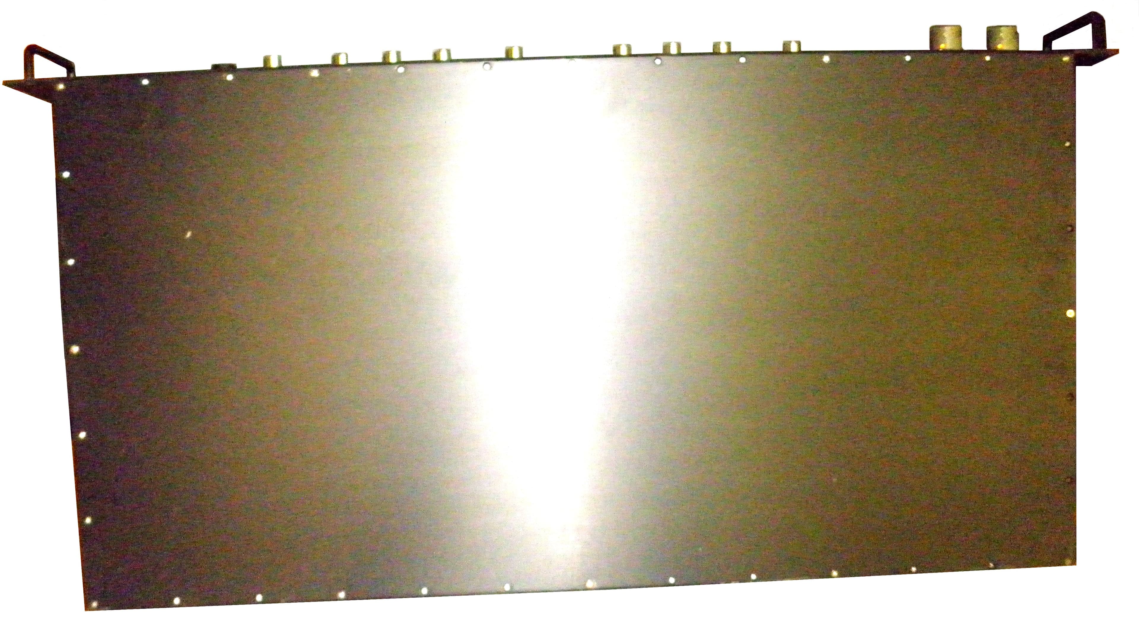
NVRCSIDRACELAAWS
Aug 23, 2015AWS Repeater
Equipment Class
B2I - Part 20 Industrial Booster (CMRS)
NVRCSICPBHMG-C4
Apr 30, 2013The Co-Pilot Beacon C4
Equipment Class
TNB - Licensed Non-Broadcast Station Transmitter
NVRCSICPBHMG-P4
Apr 28, 2013THE CO-PILOT BEACON P4
Equipment Class
PCB - PCS Licensed Transmitter
NVRCSICPBHMG-AW4
Dec 20, 2012The Co-Pilot Beacon
Equipment Class
TNB - Licensed Non-Broadcast Station Transmitter