NVRCSI2000-01Bi-Directional Amplifier
Westell, Inc.
Click to zoom
Application Details
- Equipment Class
- AMP - Amplifier
- Date of Grant
- Aug 14, 2002
- Application Purpose
- Original Equipment
- Date of Application
- Aug 14, 2002
- Equipment Note
- Bi-Directional Amplifier
- Frequency Range
- 1930.00000000 - 1990.00000000
- Company
- Westell, Inc.
- Country
- United States
Documents & Files
Document Text
Text extracted from the exhibit documents filed with the FCC. Open a document above to read the original.
Users Manual
1 PCS2000 manual 06/17/02 Cellular Specialties, Inc. Model PCS2000 Miniature In-Building Amplifier Operation and Users Manual 7 PCS2000 manual 06/17/02 3. Inspection and Installation Inspection Inspect the equipment as soon as possible after purchase. If any part of the equipment has been damaged in transit, report the damage to the transportation company and also to the company where purchased. Contents The unit package contains the following: Model PCS2000 Mini-IBA Power Transformer, 110 volt to 5 volt User Manual Optional Accessories Accessories are available directly from Cellular Specialties, Inc. or any of CSI’s distributors. Exterior High Gain Antenna Interior Omni Antenna Installation Note: The Installer should refer to the Safety Precautions, in the following section, for proper antenna selection and installation The installation of the Mini-IBA is relatively simple. If possible, measurements of the Received Signal Strength Indicator (RSSI) should be recorded as close as possible to the proposed exterior antenna location. Optimum performance will be obtained with RSSI readings greater than –85 dBm. With the exact location of the exterior antenna and the coordinates of the cell sits closest to the building in which the unit is being installed, the distance and bearings to each of the local cells can be determined. The first choice would be the closest site unless there is blockage in the form of buildings or terrain. If blockage exists, an alternate site may be available. 8 PCS2000 manual 06/17/02 If coordinates are not available, measure the RSSI at the external antenna output by connecting a phone to the external antenna and slowly rotating the antenna until a maximum reading is obtained. The Mini-IBA and interior antenna should be centrally located, keeping coaxial cable runs to a minimum. A maximum length of 100 feet of low loss cable is recommended. The actual coax used should be RG-8 type with a flame retardant rating as a minimum. If the coax is run through an area where heating and/or cooling air is channeled, a plenum rated coax should be used. When mounting the amplifier, take care to avoid areas of high heat or extreme cold. In general, do not place the unit on or near the top of high ceilings, by heaters or in cold storage areas. During installation, care must be taken to provide the maximum isolation between interior and exterior antennas. This isolation should be at least 70 dB to prevent any re-generative feedback in the system. Feedback of this nature may cause the amplifier to emit a continuous signal at maximum amplitude and could, in some cases, interfere with the normal operation of the cell site. There are no installation or user adjustments or tuning on this unit. 9 PCS2000 manual 06/17/02 Safety Precautions CAUTION For INDOOR use, an Omni-Directional Antenna with a maximum gain of 8dBi is authorized for use with this unit. Inside antennas must be positioned to observe minimum separation of 20 cm. (~ 8 in.) from all users and bystanders. For the protection of personnel working in the vicinity of inside (downlink) antennas, the following guidelines for minimum distances between the human body and the antenna must be observed. The installation of an INDOOR antenna must be such that, under normal conditions, all personnel cannot come within 20 cm. (~ 8.0 in.) from any inside antenna. Exceeding this minimum separation will ensure that the employee or bystander does not receive RF-exposure beyond the Maximum Permissible Exposure according to section 1.1310 i.e. limits for General Population/Uncontrolled Exposure. For OUTDOOR use, a Directional Antenna up to a maximum gain of 13dBi is authorized for use with this unit. The Outside antenna must be positioned to observe minimum separation of 20 cm. (~ 8 in.) from all users and bystanders. For the protection of personnel working in the vicinity of outside (uplink) antennas, the following guidelines for minimum distances between the human body and the antenna must be observed. The installation of an OUTDOOR antenna must be such that, under normal conditions, all personnel cannot come within 20 cm. (~ 8 in.) from the outside antenna. In all installations, the antenna should never be mounted such that the main beam is directed toward an area where workers or bystanders may be present. Exceeding this minimum separation will ensure that the worker or bystander does not receive RF-exposure beyond the Maximum Permissible Exposure according to section 1.1310 i.e. limits for General Population/Uncontrolled Exposure. ! !
External Photos
EXHIBIT C - EUT EXTERNAL PHOTOGRAPHS Chassis - Top View Chassis - Bottom View Chassis - Front View Chassis - Rear View Power Adapter - Overall View
ID Label/Location Info
EXHIBIT A - FCC PRODUCT LABELING AND WARNING STATEMENT FCC ID Label Specifications: Text is black or white in color and is left justified. Labels are silk-screened and shall be “permanently affixed” at a conspicuous location on the EUT. Proposed Label Location on EUT FCC Warning Statement A FCC Warning Statement is provided in the product manual.
Internal Photos
EXHIBIT C - EUT INTERNAL PHOTOGRAPHS Main Board - Top View Main Board - Bottom View
Operational Description
1 PCS2000 manual 06/17/02 Cellular Specialties, Inc. Model PCS2000 Miniature In-Building Amplifier Operation and Users Manual 2 PCS2000 manual 06/17/02 Table of Contents 1. Product Description Background Functional Description Circuit Description Functional Block Diagram Outline Drawing 2. General Specifications 3. Inspection and Installation Inspection of Contents Package Contents Installation Safety 3 PCS2000 manual 06/17/02 1. Product Description Background The performance of a wireless phone can be easily degraded when in enclosed structures where signals from a local cell site are not sufficient for reliable phone operation. The Model PCS2000 Miniature In-Building Amplifier (Mini-IBA) was developed by Cellular Specialties, Inc. (CSI) to enhance performance within these enclosed structures. Specifically, the Mini-IBA is designed to cover small areas such as home offices, small workshops, etc. Functional Description The Mini-IBA boosts the cellular performance by providing amplification of both transmit and receive signals. The unit receives the portable phone’s signal through an interior antenna, amplifies it and then sends it to an outside antenna. This signal is referred to as the “Uplink”. The Mini-IBA also receives signals from the Cell Site base station through the outside antenna. This signal is amplified and re-radiated to the portable phone and is referred to as the “Downlink”. It is necessary that sufficient signal be available at the external antenna. The external antenna is usually a directional type such as a “Yagi”, however an Omni-directional antenna may be used when the structure is located in close proximity to one or more cell sites. Internal antennas are usually Omni-directional although other types, such as low profile wall or ceiling mount, may be used for special installations. As shown in Figure 1, there are three stages of gain in both the Downlink and Uplink for a typical gain of 40 dB in each link. The maximum linear output power for the Uplink is 100 milliwatts and 30 milliwatts for the Downlink. An LED on the unit indicates the application of power. 4 PCS2000 manual 06/17/02 Circuit Description Uplink The uplink RF circuit consists of three (3) stages of gain. Each gain stage is a monolithic integrated circuit (mmic) mounted to a printed circuit board (PCB). The signal received by the inside antenna is directed to the 1 st mmic stage by a frequency diplexer, which separates the uplink frequency (1850- 1910 MHz) from the downlink frequency (1930-1995 MHz). This signal is amplified by the mmic stages and directed to an identical diplexer at the output of the 2 nd stage. A total of four (4) band-pass Surface Acoustic Wave (SAW) filters are used between active stages to provide adequate isolation of the downlink chain. All stages are biased for linear operation. The overall gain from the inside antenna terminal to the outside antenna terminal is a maximum 40 dB. Each diplexer / filter combination provides 50 dB of rejection between the uplink amplifier chain and the downlink. Downlink The downlink circuit is identical in operation to the uplink. The only differences are the downlink frequency (1930-1945 MHz) and signal flow in the opposite direction. Power Supply All the mmic amplification stages, in both the uplink and downlink, operate from a single supply voltage of +5 Vdc. A “Wall” power supply and dc-dc converter is used to provide a regulated 5 volts from an input of 110 Vac. All internal dc circuits are filtered and de-coupled from the RF circuits. The overall current at 5 Vdc is less than 1.0 Amp. 5 PCS2000 manual 06/17/02 FIGURE 1 Functional Block Diagram FIGURE 2 Outline Drawing 6 PCS2000 manual 06/17/02 2. General Specifications All specifications stated as typical unless otherwise noted. Uplink Downlink Frequency Bands (MHz) PCS 1850-1910 1930-1990 Linear Gain (dB) 40 40 Typical Power Out (max) 1 dB Compression +23 dBm +17 dBm Linear +20 dBm +15 dBm Noise Figure 6 dB 6 dB Propagation Delay <1 microsecond <1 microsecond VSWR <2:1 <2:1 Passband Ripple 5 dB pk-pk 5 dB pk-pk Connectors Type-N Power Requirements +5 Vdc, 1.0 A Dimensions 3.5”x6.5”x1.5” max Weight 1 lbs. Indicator LED “Power-On” Cellular Specialties, Inc. reserves the right to change these specifications at any time without prior notice.
Parts List/Tune Up Info
MODEL PCS2000 BDA Circuit Description Uplink The uplink RF circuit consists of three (3) stages of gain. Each gain stage is a monolithic integrated circuit (mmic) mounted to a printed circuit board (PCB). The signal received by the inside antenna is directed to the 1 st mmic stage by a frequency diplexer, which separates the uplink frequency (1850-1910 MHz) from the downlink frequency (1930- 1995 MHz). This signal is amplified by the mmic stages and directed to an identical diplexer at the output of the 2 nd stage. A total of four (4) band-pass Surface Acoustic Wave (SAW) filters are used between active stages to provide adequate isolation of the downlink chain. All stages are biased for linear operation. The overall gain from the inside antenna terminal to the outside antenna terminal is a maximum 40 dB. Each diplexer / filter combination provides 50 dB of rejection between the uplink amplifier chain and the downlink. Downlink The downlink circuit is identical in operation to the uplink. The only differences are the downlink frequency (1930-1945 MHz) and signal flow in the opposite direction. Power Supply All the mmic amplification stages, in both the uplink and downlink, operate from a single supply voltage of +5 Vdc. A “Wall” power supply and dc-dc converter is used to provide a regulated 5 volts from an input of 110 Vac. All internal dc circuits are filtered and de- coupled from the RF circuits. The overall current at 5 Vdc is less than 1.0 Amp.
Test Report
Note: This test report is specially limited to the above client company and the product model only. It may not be duplicated without prior written consent of Bay Area Compliance Laboratory Corporation. This report must not be used by the client to claim product endorsement by NVLAP or any agency of the U.S. Government. FCC PART 24 TYPE APPROVAL EMI MEASUREMENT AND TEST REPORT For Cellular Specialties, Inc. 670 N. Commercial St. Manchester NH 03101 FCC ID: NVRCSI2000-01 July 24, 2002 This Report Concerns: Original Report Equipment Type: PCS Amplifier Test Engineer: Benjamin Jing Report No.: R0206143 Test Date: July 12, 2002 Reviewed By: Jeff Lee Prepared By: Bay Area Compliance Laboratory Corporation 230 Commercial Street Sunnyvale, CA 94085 Tel: (408) 732-9162 Fax: 9408) 732 9164 Cellular Specialties, Inc. FCC ID: NVRCSI2000-01 Report # R0001071.doc Page 2 of 18 FCC Part 24 Type Approval report TABLE OF CONTENTS 1 - GENERAL INFORMATION..................................................................................................................................4 1.1 PRODUCT DESCRIPTION FOR EQUIPMENT UNDER TEST (EUT) ..............................................................................4 1.2 OBJECTIVE.............................................................................................................................................................4 1.3 RELATED SUBMITTAL(S)/GRANT(S) ......................................................................................................................4 1.4 TEST METHODOLOGY............................................................................................................................................4 1.5 TEST FACILITY.......................................................................................................................................................5 1.6 TEST EQUIPMENT LIST...........................................................................................................................................5 1.7 LOCAL SUPPORT EQUIPMENT LIST AND DETAILS...................................................................................................6 1.8 EXTERNAL I/O CABLING LIST AND DETAILS.........................................................................................................6 2 - SYSTEM TEST CONFIGURATION.....................................................................................................................7 2.1 JUSTIFICATION.......................................................................................................................................................7 2.2 BLOCK DIAGRAM...................................................................................................................................................7 2.3 TEST SETUP BLOCK DIAGRAM...............................................................................................................................7 2.4 EQUIPMENT MODIFICATIONS.................................................................................................................................7 3 - SUMMARY OF TEST RESULTS..........................................................................................................................8 4 - RF POWER OUTPUT .............................................................................................................................................9 4.1 APPLICABLE STANDARD........................................................................................................................................9 4.2 TEST PROCEDURE..................................................................................................................................................9 4.3 TEST EQUIPMENT...................................................................................................................................................9 4.4 TEST RESULTS.......................................................................................................................................................9 4.5 PLOTS OF RF OUTPUT POWER................................................................................................................................9 5 - EMISSION BANDWIDTH ...................................................................................................................................10 5.1 APPLICABLE STANDARDS.....................................................................................................................................10 5.2 TEST PROCEDURE................................................................................................................................................10 5.3 TEST EQUIPMENT.................................................................................................................................................10 5.4 PLOTS OF OCCUPIED BANDWIDTH.......................................................................................................................10 6 - OUT OF BAND EMISSIONS AT ANTENNA TERMINALS ...........................................................................11 6.1 APPLICABLE STANDARDS.....................................................................................................................................11 6.2 TEST PROCEDURE................................................................................................................................................11 6.3 TEST EQUIPMENT.................................................................................................................................................11 6.4 TEST RESULTS.....................................................................................................................................................11 6.5 PLOTS OF OUT-OF-BAND EMISSIONS AT ANTENNA TERMINAL............................................................................11 7 - TWO-TONE TEST…
Text truncated - open the document above for the full version.
Contact Information
Applicant
Joseph K Gage(Compliance Engineer)
Test Firm
Bay Area Compliance LaboratoryJohn Chan
Technical Specifications
| # | Rule Parts | Frequency Range | Power Output | Emission | Tolerance |
|---|---|---|---|---|---|
| 2 | 24,24 | 1.93 GHz - 1.99 GHz | 27.00 mW | EXTEND | Amp |
Other Applications from Westell, Inc.

NVRDPSA81090-78
Jan 25, 2021700/800 MHZ DUAL BAND INDUSTRIAL BOOSTER
Equipment Class
B2I - Part 20 Industrial Booster (CMRS)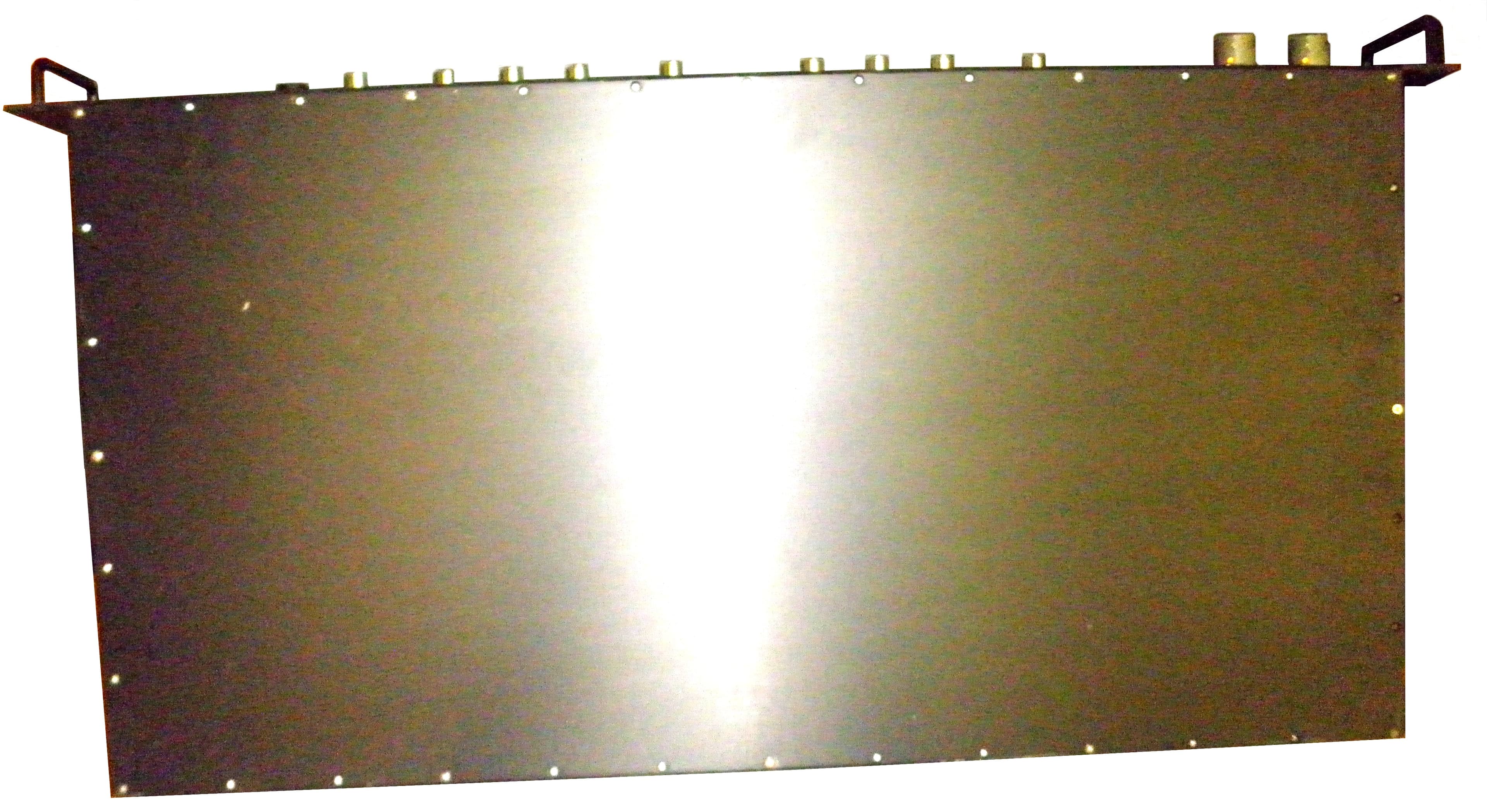
NVRCSIDRACELAAWS
Aug 23, 2015AWS Repeater
Equipment Class
B2I - Part 20 Industrial Booster (CMRS)
NVRCSICPBHMG-C4
Apr 30, 2013The Co-Pilot Beacon C4
Equipment Class
TNB - Licensed Non-Broadcast Station Transmitter
NVRCSICPBHMG-P4
Apr 28, 2013THE CO-PILOT BEACON P4
Equipment Class
PCB - PCS Licensed Transmitter
NVRCSICPBHMG-AW4
Dec 20, 2012The Co-Pilot Beacon
Equipment Class
TNB - Licensed Non-Broadcast Station Transmitter