NWNM104XTimer Console
FarmTek Inc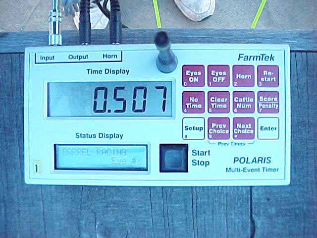
Click to zoom
Application Details
- Equipment Class
- DXX - Part 15 Low Power Communication Device Transmitter
- Date of Grant
- Jan 18, 2005
- Application Purpose
- Original Equipment
- Date of Application
- Jan 18, 2005
- Equipment Note
- Timer Console
- Frequency Range
- 903.37000000 - 921.37000000
- Company
- FarmTek Inc
- Country
- United States
Documents & Files
Document Text
Text extracted from the exhibit documents filed with the FCC. Open a document above to read the original.
Users Manual
1 DOG AGILITY SOFTWARE VERSION 1.0 AKC OR CKC VENUE Standard & JWW Classes Setup Procedure With the Timer stopped, press SETUP to open the menu Press ENTER to select Dog Agility Rules Press ENTER to select AKC or CKC RULES Press ENTER for STANDARD COURSE TIME Key in the STANDARD COURSE TIME using the numbers in the lower left hand corner of each keypad key HINT: Press and hold the clear key to reset the time to “0" in the event you put in the incorrect time Press ENTER after you have selected the correct time HINT: The Maximum Course Time will automatically be set at 1.5 times the Standard Course Time per AKC and CKC Rules Press ENTER for Faults/Second Default is preset at 1 Fault/Second. If you do not have computer scoring, this can be set at 1 Fault/Second for Novice, 2 Faults per second for Open or 3 Faults/Second for Excellent to calculate Time Faults. HINT: Press NEXT CHOICE on the Keypad to pass any menu choice that does not need to be set or reset Press ENTER to Set Finish Eye Press Enter the Finish Eye Menu If the last obstacle is not used on course as any other obstacle, select Stop on Pass 1 If the last obstacle is used once on course before the last jump, press NEXT CHOICE and select Stop on Pass 2 If the last obstacle is used twice on course before the last jump, press NEXT CHOICE twice and select Stop on Pass 3 HINTS: 1 - Press SETUP at any time to exit the SETUP mode 2 - An asterisk will identify the selected mode - e.g. *AKC Rules or *Stop on Pass 1 3 - All parameters can be updated individually and in any order desired 4 - All changes are automatically stored in the timer until changed again in the future Operating Procedures for Human Timer Verify that the eyes are adjusted to the correct jump height at the beginning of the class and with each jump height change. Assuming everything goes normally, the time will automatically start and stop - simply show the time to the scribe to copy down. If the time does not start, press the HORN key to stop the run before the third obstacle. If a dog takes the last obstacle out of sequence or if the Timer stops in error, press RESTART on the keypad to resume timing as if the timer had never been stopped. If a dog is excused or fails to complete the course, press the START/STOP key to stop the time and report “no time” to the scribe. HINTS: 1 - There is no need to clear the time after each run. 2 - If a closed tunnel or a broad jump is the last obstacle, the timer will need to stop the time manually with the START/STOP key when the dog crosses the finish line. 3 - Use the PREV & NEXT keys to scan back and forth through previous times - this can be done and viewed in the lower window even while a dog is running. 2 DOG AGILITY SOFTWARE VERSION 1.0 USDAA, AAC, ASCA and NADAC VENUES Standard & JWW Classes Setup Procedure With the timer stopped, press SETUP to open the menu Press ENTER to select Dog Agility Rules Press ENTER to select USDAA, AAC, ASCA or NADAC RULES Press ENTER for STANDARD COURSE TIME Key in the STANDARD COURSE TIME using the numbers in the lower left hand corner of each keypad key HINTS: Press and hold the clear key to reset the time to “0" in the event you put in the incorrect time If you leave STANDARD COURSE TIME at 0.00, be sure to select No Game Horns in the Game Horn Menu Press ENTER after you have selected the correct time Press ENTER for MAXIMUM COURSE TIME Key in the MAXIMUM COURSE TIME using the numbers in the lower left hand corner of each keypad key HINT: If you leave this set at 0.00, there will not be a maximum course time Press ENTER after you have selected the correct time Press ENTER for Faults/Second Default is preset at 1 Fault/Second. HINT: Press NEXT CHOICE on the Keypad to pass any menu choice that does not need to be set or reset Press ENTER to Set Finish Eye Press Enter If the last obstacle is not used on course as any other obstacle, select Stop on Pass 1 If the last obstacle is used once on course before the last jump, press NEXT CHOICE and select Stop on Pass 2 If the last obstacle is used twice on course before the last jump, press NEXT CHOICE twice and select Stop on Pass 3 Press SETUP to exit the Setup menu HINTS: 1 - Press SETUP at any time to exit the SETUP mode 2 - An asterisk will identify the selected mode - e.g. *AKC Rules or *Stop on Pass 1 3 - All parameters can be updated individually and in any order desired 4 - All changes are automatically stored in the timer until changed again in the future Operating Procedures for Human Timer Verify that the eyes are adjusted to the correct jump height at the beginning of the class and with each jump height change. Assuming everything goes normally, the time will automatically start and stop - simply show the time to the scribe to copy down. If the time does not start, press the HORN key to stop the run before the third obstacle. If a dog takes the last obstacle out of sequence or if the Timer stops in error, press RESTART on the keypad to resume timing as if the timer had never been stopped. If a dog is excused or fails to complete the course, press the START/STOP key to stop the time and report “no time” to the scribe. HINTS: 1 - There is no need to clear the time after each run. 2 - If a closed tunnel or a broad jump is the last obstacle, the timer will need to stop the time manually with the START/STOP key when the dog crosses the finish line. 3 - Use the PREV & NEXT keys to scan back and forth through previous times - this can be done and viewed in the lower window even while a dog is running. 3 Gambler’s Class Setup Procedure If the start line is the length of the ring, place the timer at either end of the start line With the timer stopped, press SETUP to open the menu Press ENTER to select Dog Agility Rules Press ENTER to select USDAA, AAC, ASCA or NADAC RULES Press NEXT CHOICE to skip STANDARD COURSE TIME Press NEXT CHOICE to skip MAXIMUM COURSE TIME Press NEXT CHOICE to skip Faults/Second Press NEXT CHOICE to skip Set Finish Eye Press …
Text truncated - open the document above for the full version.
Cover Letter(s)
scott To: '[email protected]'; '[email protected]' Cc: '[email protected]' Subject: FCC ID: NWNM104X 12/23/2004 Mr. Fujimoto: In order for processing of this application (FCC ID: NWNM104X) to continue, the following issue(s) will have to be addressed: 1) Please indicate the type of modulation the system utilizes If the device uses pulsed modulation, please submit plots of the duty cycle, accompanied by the calculations used for determining the percentage. 2) Please indicate the procedure used for determining the average level of the emissions, where appropriate. 3) Please submit data showing compliance of the device at and/or just outside the band edges of the 902 to 928 MHz band. 4) The block diagram submitted is not sufficient. As per section 2.1033(b)(5) of the rules, the block diagram shall show “the frequency of all oscillators in the device. The signal path and frequency shall be indicated at each block. The tuning range(s) and intermediate frequency(ies) shall be indicated at each block.” Please resubmit. 5) The schematic diagram submitted is not sufficient. It does not show the values of any components. Also, there is no schematic for the RF section. Please resubmit. 6) The internal photos show what appears to be a metal shield over the RF section. Please provide photos with the shield removed. 7) The modification letter does not indicate that the modifications will be implemented into product models. Please submit a new letter. 8) Please indicate what the “input” port is used for, and to what it is typically connected. 9) Please indicate whether the cables with ferrites for all three ports (input, output, horn) are provided for each device. If cables are not provided for one or more of these ports, please indicate how compliance will be maintained if the user plugs in his own cable. If cables are provided for all ports, please indicate by what method the applicant has taken to prevent the user from plugging in an alternate cable without ferrites. Is the connector a non‐standard type? Are instructions provided? Please explain in detail. The item(s) indicated above must be submitted before processing can continue on the above referenced application. Failure to provide the requested information within 60 days of the original e‐mail date may result in application dismissal and forfeiture of the filing fee. Also, please note that partial responses increase processing time and should not be submitted. Please upload responses and/or exhibits to the electronic filing website. Your correspondence number is NWNM104X‐1. Best regards, Scott McCutchan Operations Manager Compatible Electronics TCB (714) 579‐0500 Direct: (714) 579‐1489 Fax: (714) 579‐1850 [email protected] Best regards, Scott McCutchan Engineering Manager Compatible Electronics, Inc. (714) 579-0500 Direct: (714) 579-1489 Fax: (714) 579-1850 [email protected] 12/23/2004 Correspondence by Project Project Number: 2135132874 Correspondence Number Memo NWNM104X-1 1) Please indicate the type of modulation the system utilizes If the device uses pulsed modulation, please submit plots of the duty cycle, accompanied by the calculations used for determining the percentage. Response: The EUT uses FSK modulation -- which is not pulse modulation. 2) Please indicate the procedure used for determining the average level of the emissions, where appropriate. Response: The frequencies above 1 GHz were averaged manually by narrowing the video filter (VBW) down to 10 Hz and putting the sweep time on AUTO on the EMI Receiver to keep the amplitude reading calibrated. 3) Please submit data showing compliance of the device at and/or just outside the band edges of the 902 to 928 MHz band. Response: There were NO emissions detected at 902 MHz and 928 MHz. Please note the 20 dB bandwidth of each signal was only 511 kHz. 4) The block diagram submitted is not sufficient. As per section 2.1033(b)(5) of the rules, the block diagram shall show “the frequency of all oscillators in the device. The signal path and frequency shall be indicated at each block. The tuning range (s) and intermediate frequency(ies) shall be indicated at each block.” Please resubmit. Response: Please see the Revised Block Diagram exhibit. 5) The schematic diagram submitted is not sufficient. It does not show the values of any components. Also, there is no schematic for the RF section. Please resubmit. Response: The schematics have been revised -- a separate pa ge will show the component values of each location. 6) The internal photos show what appears to be a metal shield over the RF section. Please provide photos with the shield removed. Response: Please see the Internal Photo exhibit for this. 7) The modification letter does not indicate that the modifications will be implemented into product models. Please submit a new letter. Response: Please see the revised Modification letter exhibit 8) Please indicate what the “input” port is used for, and to what it is typically connected. Response: Please see the exhibit showing definitions of ports. 9) Please indicate whether the cables with ferrites for all three ports (input, output, horn) are provided for each device. If cables are not provided for one or more of these ports, please indicate how compliance will be maintained if the user plugs in his own cable. If cables are provided for all ports, please indicate by what method the applicant has taken to prevent the user from plugging in an alternate cable without ferrites. Is the connector a non- standard type? Are instructions provided? Please explain in detail. Response: Please see the revised owner's manual. The EUT will be provided with cables and a statement to the effect not using the cables provided will void FCC compliance.
Test Report
Report Number: B41203A1 FCC Part 15 Subpart B and FCC Section 15.249 Test Report Timer Console Model: Polegro Brea Division 114 Olinda Drive Brea, CA 92823 (714) 579-0500 Agoura Division 2337 Troutdale Drive Agoura, CA 91301 (818) 597-0600 Silverado Division 19121 El Toro Road Silverado, CA 92676 (949) 589-0700 Lake Forest Division 20621 Pascal Way Lake Forest, CA 92630 (949) 587-0400 Page 1 of 16 FCC PART 15, SUBPART B and C TEST REPORT for TIMER CONSOLE MODEL: POLEGRO Prepared for FARMTEK, INC. 1000-D HIGHWAY 78 NORTH WYLIE, TEXAS 75098 Prepared by:_____________________ KYLE FUJIMOTO Approved by:____________________ MICHAEL CHRISTENSEN COMPATIBLE ELECTRONICS INC. 114 OLINDA DRIVE BREA, CALIFORNIA 92823 (714) 579-0500 DATE: DECEMBER 7, 2004 REPORT APPENDICES TOTAL BODY A B C D E PAGES 16 2 2 2 20 19 61 This report shall not be reproduced except in full, without the written approval of Compatible Electronics. Report Number: B41203A1 FCC Part 15 Subpart B and FCC Section 15.249 Test Report Timer Console Model: Polegro Brea Division 114 Olinda Drive Brea, CA 92823 (714) 579-0500 Agoura Division 2337 Troutdale Drive Agoura, CA 91301 (818) 597-0600 Silverado Division 19121 El Toro Road Silverado, CA 92676 (949) 589-0700 Lake Forest Division 20621 Pascal Way Lake Forest, CA 92630 (949) 587-0400 Page 2 of 16 TABLE OF CONTENTS Section / Title PAGE GENERAL REPORT SUMMARY 4 SUMMARY OF TEST RESULTS 4 1. PURPOSE 5 2. ADMINISTRATIVE DATA 6 2.1 Location of Testing 6 2.2 Traceability Statement 6 2.3 Cognizant Personnel 6 2.4 Date Test Sample was Received 6 2.5 Disposition of the Test Sample 6 2.6 Abbreviations and Acronyms 6 3. APPLICABLE DOCUMENTS 7 4. DESCRIPTION OF TEST CONFIGURATION 8 4.1 Description Of Test Configuration - EMI 8 4.1.1 Cable Construction and Termination 9 5. LISTS OF EUT, ACCESSORIES AND TEST EQUIPMENT 10 5.1 EUT and Accessory List 10 5.2 EMI Test Equipment (Part 1) 11 5.3 EMI Test Equipment (Part 2) 12 6. TEST SITE DESCRIPTION 13 6.1 Test Facility Description 13 6.2 EUT Mounting, Bonding and Grounding 13 7. TEST PROCEDURES 14 7.1 Conducted Emissions Test 14 7.2 Radiated Emissions (Spurious and Harmonics) Test 15 8. CONCLUSIONS 16 Report Number: B41203A1 FCC Part 15 Subpart B and FCC Section 15.249 Test Report Timer Console Model: Polegro Brea Division 114 Olinda Drive Brea, CA 92823 (714) 579-0500 Agoura Division 2337 Troutdale Drive Agoura, CA 91301 (818) 597-0600 Silverado Division 19121 El Toro Road Silverado, CA 92676 (949) 589-0700 Lake Forest Division 20621 Pascal Way Lake Forest, CA 92630 (949) 587-0400 Page 3 of 16 LIST OF APPENDICES APPENDIX TITLE A Laboratory Recognitions B Modifications to the EUT C Additional Models Covered Under This Report D Diagrams, Charts, and Photos • Test Setup Diagrams • Radiated Emissions Photos • Antenna and Effective Gain Factors E Data Sheets LIST OF FIGURES FIGURE TITLE 1 Plot Map and Layout of the 3 Meter Radiated Test Site 2 Plot Map And Layout of the 10 Meter Radiated Test Site Report Number: B41203A1 FCC Part 15 Subpart B and FCC Section 15.249 Test Report Timer Console Model: Polegro Brea Division 114 Olinda Drive Brea, CA 92823 (714) 579-0500 Agoura Division 2337 Troutdale Drive Agoura, CA 91301 (818) 597-0600 Silverado Division 19121 El Toro Road Silverado, CA 92676 (949) 589-0700 Lake Forest Division 20621 Pascal Way Lake Forest, CA 92630 (949) 587-0400 Page 4 of 16 GENERAL REPORT SUMMARY This electromagnetic emission test report is generated by Compatible Electronics Inc., which is an independent testing and consulting firm. The test report is based on testing performed by Compatible Electronics personnel according to the measurement procedures described in the test specifications given below and in the "Test Procedures" section of this report. The measurement data and conclusions appearing herein relate only to the sample tested and this report may not be reproduced without the written permission of Compatible Electronics, unless done so in full. This report must not be used to claim product endorsement by NVLAP, NIST or any other agency of the U.S. Government. Device Tested: Timer Console Model: Polegro S/N: N/A Product Description: See Expository Statement Modifications: The EUT was modified in order to meet the specifications. Please see the list located in Appendix B. Manufacturer: FarmTek, Inc. 1000-D Highway 78 North Wylie, Texas 75098 Test Dates: December 2 and 3, 2004 Test Specifications : EMI requirements CFR Title 47, Part 15 Subpart B; and Subpart C, Sections 15.205, 15207, 15.209 and 15.249 Test Procedure: ANSI C63.4: 2003 Test Deviations: The test procedure was not deviated from during the testing. SUMMARY OF TEST RESULTS TEST DESCRIPTION RESULTS 1 Conducted RF Emissions, 150 kHz - 30 MHz This test was not performed because the EUT operates on 4 “AA” batteries only and cannot be plugged into the AC public mains. 2 Radiated RF Emissions, 10 kHz - 9300 MHz Complies with the Class A limits of CFR Title 47, Part 15, Subpart B; and the limits of Subpart C, sections 15.205, 15.209, and 15.249. Report Number: B41203A1 FCC Part 15 Subpart B and FCC Section 15.249 Test Report Timer Console Model: Polegro Brea Division 114 Olinda Drive Brea, CA 92823 (714) 579-0500 Agoura Division 2337 Troutdale Drive Agoura, CA 91301 (818) 597-0600 Silverado Division 19121 El Toro Road Silverado, CA 92676 (949) 589-0700 Lake Forest Division 20621 Pascal Way Lake Forest, CA 92630 (949) 587-0400 Page 5 of 16 1. PURPOSE This document is a qualification test report based on the Electromagnetic Interference (EMI) tests performed on the Timer Console Model: Polegro. The EMI measurements were performed according to the measurement procedure described in ANSI C63.4: 2003. The tests were performed in order to determine whether the electromagnetic emissions from the equipment under test, referred to as EUT hereafter, are within the Class A specification limits defined by CFR Title 47, Part 15, Subpart B; and the limits defined in Subpart C, sections 1…
Text truncated - open the document above for the full version.
Contact Information
Applicant
Mike Douglas(President)
Technical Contact
Compatible ElectronicsKyle Fujimoto
[email protected]714-579-0500
114 Olinda Drive · Brea, California · United States
Test Firm
Compatible ElectronicsScott McCutchan
714-579-0500Fax: 714-579-1850
Technical Specifications
| # | Rule Parts | Frequency Range | Power Output |
|---|---|---|---|
| 1 | 15C | 903.37 MHz - 921.37 MHz | - |
Other Applications from FarmTek Inc
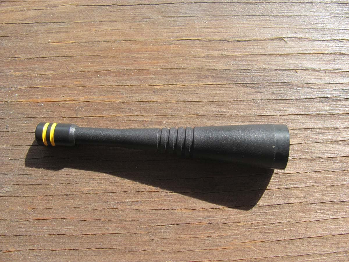
NWNMI043
Feb 23, 2011Polaris Timer Console
Equipment Class
DXT - Part 15 Low Power Transceiver, Rx Verified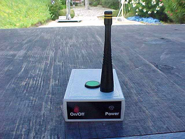
NWNMI046
Jul 19, 2005Wireless Photo-Receiver
Equipment Class
DXX - Part 15 Low Power Communication Device Transmitter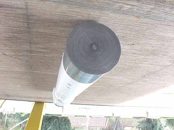
NWNM106X
Mar 15, 2004Light Curtain
Equipment Class
DXX - Part 15 Low Power Communication Device Transmitter
NWNMI052-2RB
Nov 19, 1998CSR - Scanning Receiver
Equipment Class
CSR - Scanning Receiver
NWNMI050-2RB
Oct 01, 1998DXX - Part 15 Low Power Communication Device Transmitter
Equipment Class
DXX - Part 15 Low Power Communication Device Transmitter