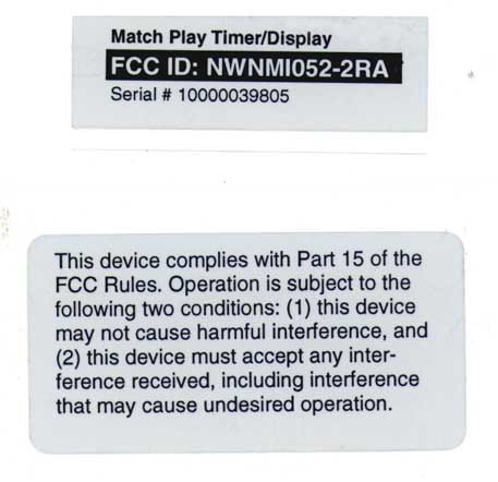
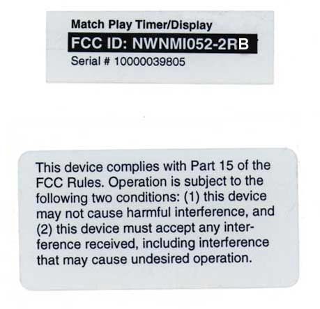
NWNMI052-2RB
FarmTek Inc
Click to zoom
Application Details
- Equipment Class
- CSR - Scanning Receiver
- Date of Grant
- Nov 19, 1998
- Application Purpose
- Original Equipment
- Date of Application
- Sep 22, 1998
- Frequency Range
- 903.30000000 - 921.30000000
- Company
- FarmTek Inc
- Country
- United States
Documents & Files
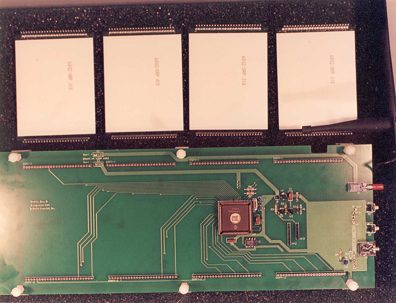
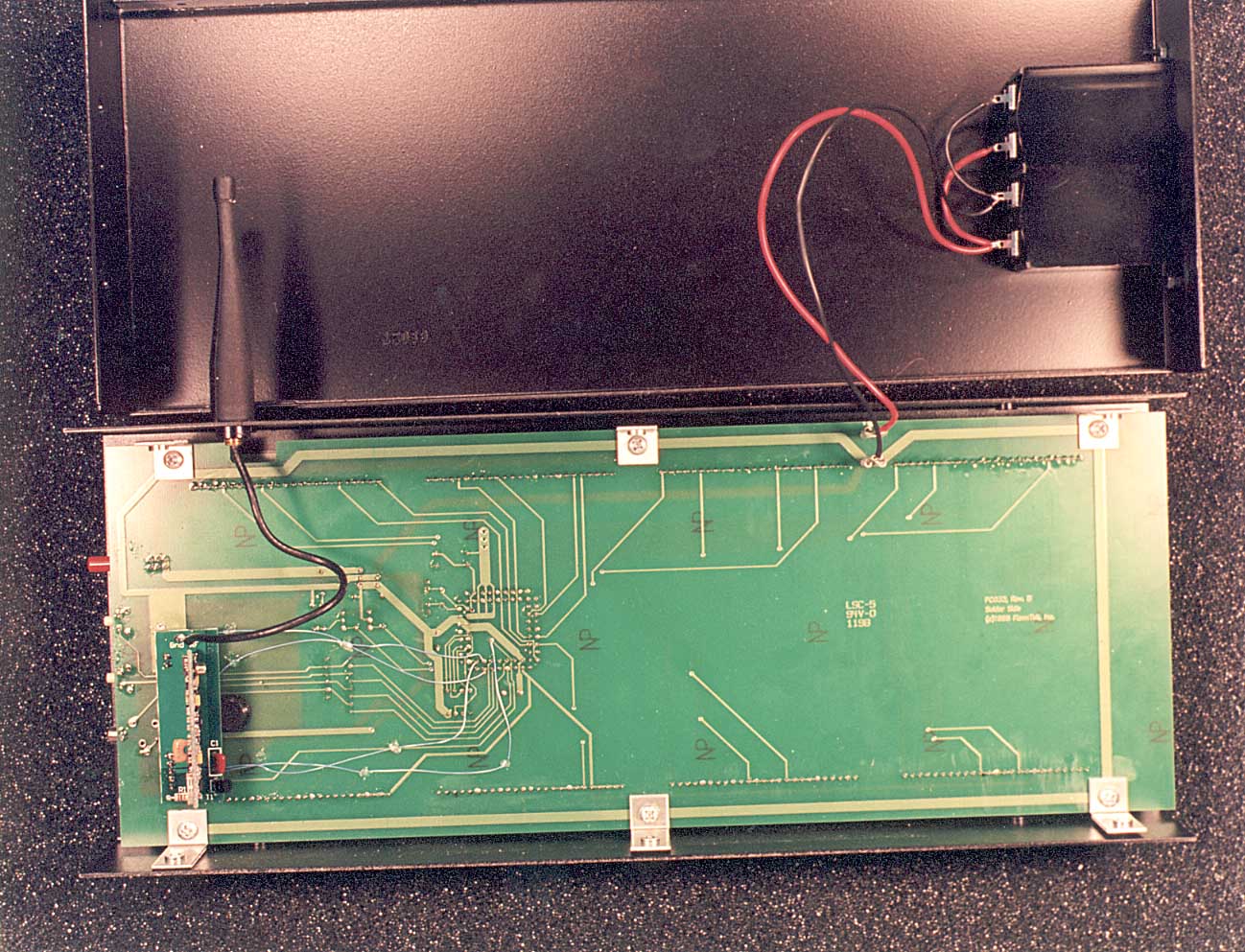
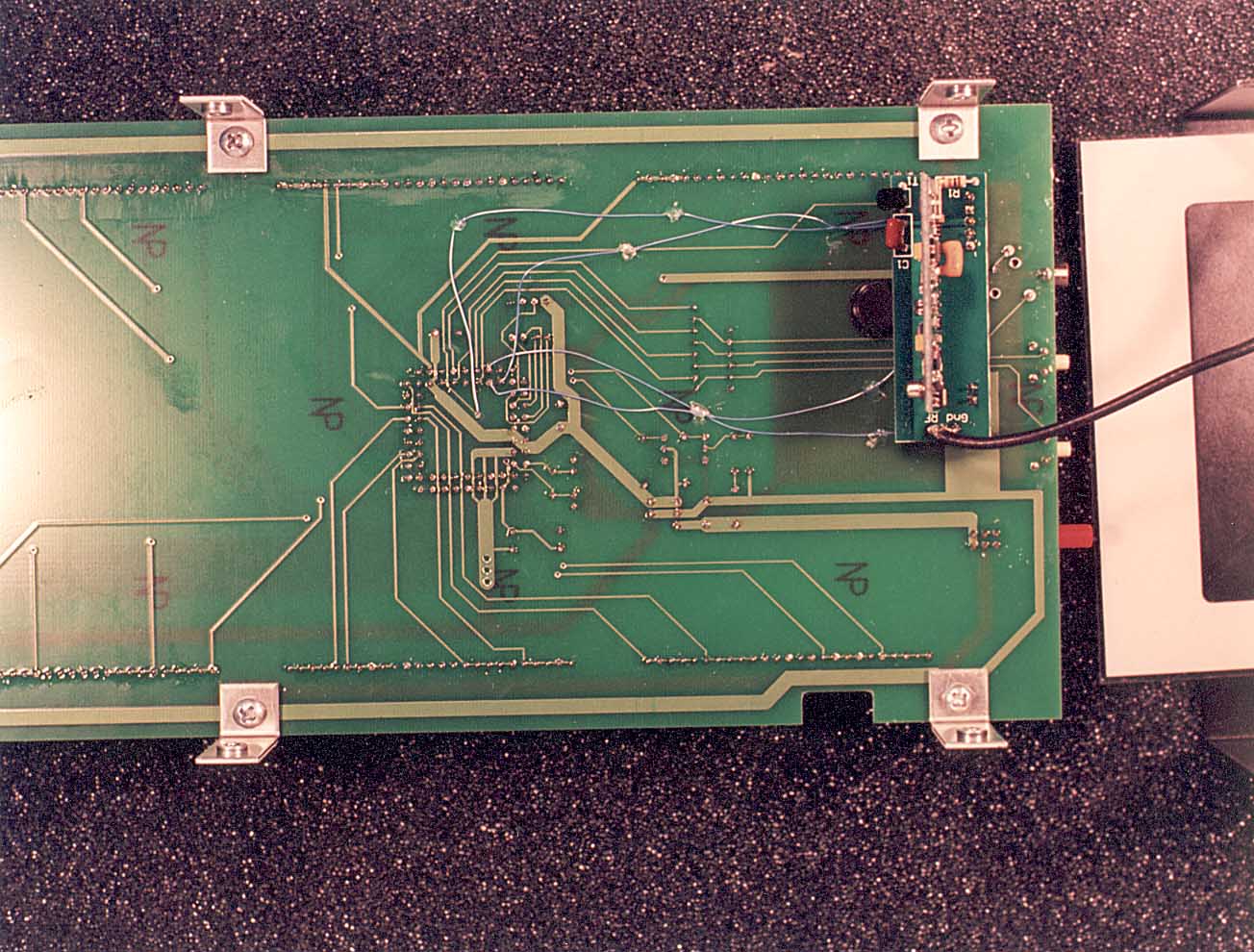
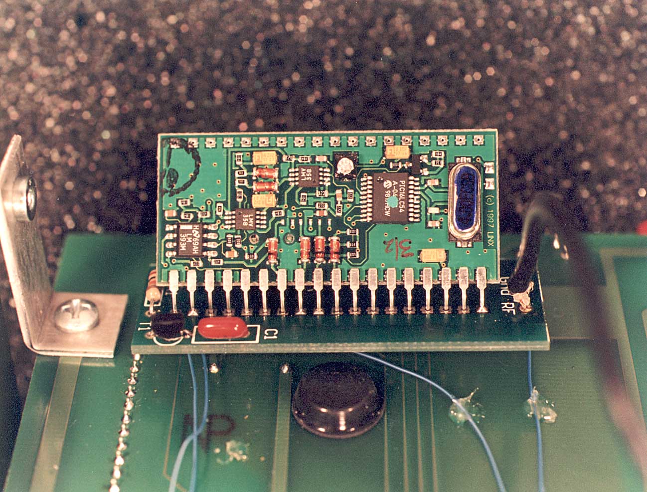
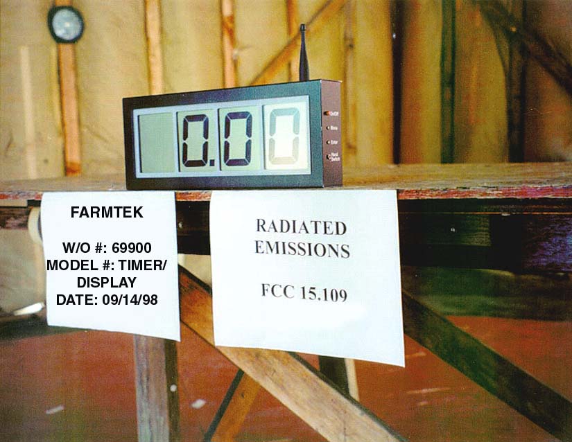
Document Text
Text extracted from the exhibit documents filed with the FCC. Open a document above to read the original.
Users Manual
Match Play Timer User's Manual Page 1 FCC Information NOTE : This equipment has been tested and found to comply with the limits for a Class B digital device, pursuant to Part 15 of the FCC Rules. These limits aredesigned to provide reasonable protection against harmful interference whenthe equipment is operated in a residential installation. This equipment gener-ates, uses, and can radiate radio frequency energy and, if not installed and usedin accordance with the instruction manual, may cause harmful interference toradio communications. However, there is no guarantee that interference willnot occur in a particular installation. If this equipment does cause harmful in-terference to radio or television reception, which can be determined by turningthe equipment off and on, the user is encouraged to try to correct the interfer-ence by one or more of the following measures: (1) Reorient or relocate the re-ceiving antenna. (2) Increase the separation between the equipment and the re-ceiver. (3) Consult the dealer or an experienced radio/TV technician for help.CAUTION : Changes made or modifications not expressly approved by the party responsible for FCC compliance of this equipment could void the user’sauthority to operate the equipment. Introduction The Match Play Electronic Timer makes timing of track events quickand easy! The timer is best suited for sprint events which start at point“A” and finish at point “B.” A photosensor pair (“electric eye”) is usedat the starting point to automatically start timing when a runner crossesthe starting line. A second photosensor pair is used at the finish line toautomatically stop timing when the runner crosses the finish line. Aseparate timing unit displays the time on a four digit display which islarge enough to be easily read from 20 to 30 feet in in door and outdoor lighting conditions. To make setup and operation simple, all units oper-ate from internal batteries, and a wireless link is used from the photo-sensor to the timing unit to signal the timer to start or stop. The MatchPlay Electronic Timer consists of the following major components: Quantity Description 2 Photo-transmitter (light source) 2 Photo-receiver (light detector) 4 Adjustable stands (to mount photo-transmittersand receivers) 1 Timing unit (four digit timing/display unit) 1 Hand-held start/stop push-button with 25 footcord to connect to the timing unit. Match Play Timer User's Manual Page 2 Preparation For Use 1) Attach each of the four electric eyes to the yellow stands by screw- ing the electric eye onto the top of the stand – tighten gently! Loos- ening the knob at the top of the stand just ½ turn allows the electriceye to be positioned at any angle as required for alignment 2) Place the electric eyes about 10 feet apart and across from each other as shown in the illustration to form the start line and the finishline. The electric eyes with the green dot form the start line. Theelectric eyes with the red dot form the finish line. 3) Turn on each electric eye by pressing the On/Off button. The red Power light illuminates when the unit is on. 4) Align each pair of electric eyes so they face each other squarely (alignment is not very critical). Adjust the stand height so the run-ners’ hips and/or torso break the beam. 5) Place the time display where it is easily seen by the record-keeper and the runners as they finish the course. Make sure the time display is at least 10 feet away from the closest Photo-Receiver (electric eye with the antenna). Turn on the time display by pressing the On/Off button. A time of “0.00” is displayed when the unit is first turned on. 6) If needed, connect the hand switch to the time display by plugging the 25 foot cable into the Hand Switch jack on the side of the time display. The hand switch is required to manually start and stop thetimer if the electric eyes are not used. The hand switch can also beused to clear the timer when required. Match Play Timer User's Manual Page 3 Timer Operation Operation of the timer is hands-free. Crossing the start line automati-cally starts timing for a runner. Crossing the finish line stops timing forthe runner and displays the runner’s time. Up to 16 runners can be onthe course at the same time. Multiple runners on course must be spaced far enough apart so they do not pass each other and so they finish atleast one second apart.If the timer gets out of sequence for any reason (a runner is passed, anextra beam break, etc), the times of all runners on course become inva-lid. Have all runners exit the course and then clear the timer. The sim-plest way to clear the timer is to: a) Press and hold down the hand switch button until the display clears to 0.00 , or... b) Turn the time display unit off and back on. Time Display The timer displays either the running time of the lead runner on thecourse, or the final time of the most recent runner. A runner’s final timeis displayed immediately when the finish line is crossed. After five sec-onds without finish line activity, the running time of the lead runner isagain displayed. If no runners are on course, then the most recent finishtime remains displayed.Times are displayed to the finest resolution possible on the four digitdisplay: Elapsed Time Resolution Display Less than 1 min. .01 sec. 00.00 to 59.99 1 to 10 minutes .1 sec. 1.00.0 to 9.59.9 10 to 60 minutes 1 sec. 10.00 to 59.59 1 to 10 hours 10 sec. 1.00.0 to 9.59.5 Hand Switch Operation Stopwatch OperationThe timer can be used as a stopwatch without using the electric eyes.Connect the hand switch to the time display by plugging the 25 foot ca-ble into the Hand Switch jack on the right side of the time display. Press the hand switch to start timing from zero (no reset required), thenpress it again to stop the timer. Match Play Timer User's Manual Page 4 Hand Switch with Electric EyesIf required, the timer can be operated with one pair of electric eyes ofinstead of two pairs. Place the electric eyes across the start line as…
Text truncated - open the document above for the full version.
Attestation Statements
II* þ ̃ º r ª ² ( È È a@a@a@a@a@a@a@a@a@a@a@a@a@a@a@a@a@a@a@a@a@a@a@a@a@a@a@a@a@a@a@a @a@a@a@a@a@a@a@a@a@a@a@a@a@a@a@a@a@a@a@a@a@a@a@a@a@a@a@a@a@a@a@a@a@a@a@a@a@a@a@a @a@a@a@a@a@a@a@a@a@a@a@a@a@a@a@a@a@a@a@a@a@a@]Àê î‡Í«]À¤ Y]À¤ Ykš|ªV ? œ2A¶K a@a@a@a@a@a@a@a@a@a@a@a@a@a@a@a@a@a@a@a@a@a@a@a@a@a@a@a@a@a@a@a@a@a@a@7U v ̈07T ÃT 7T ÃT 7S ]ª 7S ]ª 7R ]ª 7R `l7 `H\À Ø0ÌH2 ¶ ]el f$ ̧Û `] el ̧f¤ ̧Û `] el ̧f“ Xm @] Ø0Í&1q¶ ] Ø0Í&1a¶ @\ ̃el f$ °Û \ ̃»S Xb£l \ ̃ö ̈1aEFØ \ ̃Ò ¬ì°s Ô! ÌQƒl ]XªÁz Æál- 0qÌAƒl ]Xª ‰Œq`QÁ b üAƒl ]X¡ G‚ð Þ)Ã?‹Â ` ]XÂ Ï XkxÎ <\ ̧Û ]XÁƒ~ ì5¼t ü< Û ]@ áx^ ìL bp³ ...áÀ ÆØ*]@ Áf> âpN ... ̃¾/ Ä 6ÁP]@ ÁÐ|!Å ̃¾/ âÐ|1Ä 6ÁX]@(./ f9‹ÂøÎ< °V]@( & @è9‹ÃñN< Ô Ø+\ Ð... s cá| `. m‚À\ ªÃ? f: ...àÊÀ\ Û \¡ g f9‹ÂðeX0 m‚Ð\  ~ æ/ Ã*À‚ãl \Á‡ ð¤ bÌ|/ Œ ° \ ¥ÄñðÈ bÌ|/Œ ƒˆ0m P\ ¥ÇAðÈ cø_ A\Aƒl \ ¢ qðÈ 1x_ 1lTãl \ Ë ‚ठƒ ̃¼9ŒãÁà• ° \ ̧¢ ̃ ̃) ̃³ 1f. ... ̈m °\ ̧¢ ñ8a bÌ|,ÄÁ8|-Cl \ ̧¢ ü2 ̃è> ³...á4 aH\ ̧Ë ~ æ/ á£Åá4 aH\ ̧Á‚Œ ÌY‹Ã@ 1ÌB Í 30^4 ̃[n ̈\@¡ @³ cáH è9ˆ@Ù©Â¥ $Á *c(— \@ª À¶2 ̃è> 0D ‚ lÔç xœZ J DŸ] \ {+ ,lÚéÀš{b-5,Gzyt 7 5=8 OìE; ̈— @7 6º•$0÷uEÿÕiÛéF¹ 706j{P¾/c...Ö¥ yÞ8ü‡‘¼r¡ ûóúן5Í@706jw¡;À– Ö§a è ÁPô Âx·`™Eb8ìY 7H6hÂ!åvVw'ÏÛ·n(8w[ Ã8vîÆî+®Ê(nࢊF`\á’ Ù¢ }Ô]]Õu(yu ]EÐbÒêîîÊ(»Îûûºì¤d\á’ Ù ÂgóÓî꺔]w}ÝGö :ê/âê;ÿº øˆó_ \á’ © ï Ÿ ÕÔ¢ï ̈ ̄þ/«  ÑDG’ø\á’ Ù£N/Ÿ§ éêQwÔQ ÅÎ/œ â/ è §a.à\á’ ¢4QÎ~t_§©ß×QEÔsÔQ|à X[ïÁrá®j] ’ Ù¥ãÑÏzt]'Ïß×w ßôsÑ- {‚DGgu÷øï äfkªGâùé÷ý]J.»¾ÿ£ù èç¼ G ÷DŠò ŒÀkªT¢þÿ ̄ý=J.úŠ/ïù ç¾z|]= WE- WßôŒÀkª>vò»+¿OS¿þ¢‹û±¡Î‡•ÝEÜQýtOu ÿÈÐkª‡À ̧ /ugïë ̈¢êÛ ̃g g ;-Ý VwßvQ]” k’ à /szÔ¢ ë»ïû h xœ%ö ö Ü \Ôk¬Ô£ /ñ_üØö¢ô9Ps.ð ½ ‡ ®8l]' -Õé{l]μ ̄ð9¹hl_μ« = ̧ lEμ¶9 mÁ l_μ±Fæà mDlœa@l©æ l©F ]8 Xa>Oj fÂÀ^°p b ̈œÚ ^°p ^ ̧œÚ ^»cÁ"sj ^»cÁ"sj ^ ̧fÿHƒ¾'FÙ ^»Qz-- œt <±×@_ d ^»@ ̃1Ã=* ºÚz ØFÉh^»K+8vwN¥”PÆPwC¹²Z^°Kú».² ;ø /Cî.›% ^°B+²ë¹Ó¾ xx ñtÙ,^°è;²ïùÓ¾qƒ ̄þ6É ^»P—eßó¼ Å/_ûÍ’@^»A ]— Îðw ½ ï6I ^ ̧7ÝÙuÜïdQ ̄ýæÉ ^ ̧;«²ïùÓጠ̄þ.›% ^ ̧;«²ïùÓ¾zá•ÿÅÓd°^ ̧; Ùwüé¼¢· _Å•í‘p^ ̧6ã‹.» C âÆñ ÿÛ á¶E ^»AGoe ßó %Ý<E ø-Í‘p]?©ß ̄ÿ¢ ýOŒ ?ýþÙ ng¶” ng¶” ne¶• a@a@a@a@a@a@a@nN< î §™²P\@Cúg-±à*ý»iÝñNmà\`ZAÓ ¤x »c“N> pû'P¦ 9Ì$Í {\`Y²»aÇ...- M7øL Á;Wx Q8. 1®à\d è?º <)lri¿–A»²È#ú ÕÃÀ ̃Üñ»\p\d è?¿ =åûÏÁqPß™Œ ê î ÿäÍT²è‹?³ }u ̃K,òË%Í@\g è?þ =ÂðßqØ „®{ ̄¬L wø#5Oïâ<¾È¹÷õÀïó"ú/×5\f ª = Þ ø(wc‡ ÝsÜú‡ ÍÝßÙ»f...Ù|‹/² wõÀàâ/¢úF \`ˆƒμa‚öò·”Ye–VòÖ»¬¡åo(¿»¶h]— Ǫ² wõá="/¢úF ]8SÁÈ- ½Ý]ÔYÿwW -wYEô]Eü_3B®ýÓ©õ\÷~àJ·?‡uÑ}#@];·H9 † Å>îî »èçi[Ë(¾‹ ̈¿‹æhU×9Ú¿«âëœ > Ò»é \b÷8;S"= å ÑL[¿ƒ³ Ûê+ çÑ Í ýÙÏÕΪ‹¬8pÃ';7d<±ÈÐ\Å8: ̧ˆô Çô\ ùð ~¢ xþ¿ø f‚Ó 83¥-w‡ è ¾ ̄ú Û” \Å8: ̧ˆô _ôXwß> È íë è¿ Fh,s- A¢ÒÊa nþ"ó Y \Å8;©ÄG¢Óþë}ÝüA/} dô_ÄÍYª¾C Ð ˆ:ÎùÁØô ‘ ^ºtàïç -Š}ÿÝw÷uwáÓº-Êjÿ¢ê)¦h_UñÞ– äAÁóƒ-ˆ¤h]=Õ ï¹‘-»«ÿºî²ÊïÈ qõô _Õÿ3B®þøö°7ŸÑ| óß\úæ ];·H;Ý°ãÖíßýÙYÝo,ˆ qý•ÿ]nÝÌл¬¾=T ë+¾ ùï¢ ésP\`CÁÓ ¤{ gýœ XL C=Îa3úÂàFh]ôS ØK¬²Ë[+±Å¥msP\@¤aÔ X÷ ßøì¢Á<aÄ] }ý„ÿ ÍR¼ZG È%âp]Ba v f;\p6 Úe= ú 2QÌs 8¾& `« ̧6 še1.I ̈ˆªÇSkØ6 úi•d‘¶ 6 ®i•Ê¹· 6 Ó,Õ#n6(& ̃.§›xmj ¦a@a@a@\ ̧Åμ ]ãÍ ” \@Q9` ÍÖ a< ́æ6 ̧= *3i \a¹‰Ë!ˆ|ÓƒÀ\ ‹Äi ÑÑÎ Æs.ôD2%ì];æ% Ǻ r†wÎ HU§*>a p *qQP_ qÀ]=8J3 í W c™õ“HU§#ØÔ Ç º›º9±Ï s\Ô]> Í §t3šI Ø ‘ S<¾i ã îåx Ye¥× ë²Ç#@]=P -...Á|Rq À d_|? ¶ ¶ »Q } Z]X¿u Ò4];ÑÃÆî ënñ»W @wd_tÿY4...dóȇ~ôˆ¾‹ í û ̈¾‘ ]8ÑevPò‹;ºQ @W‰—ÙGÍͤ- UD Íé îøˆeÿÖ§HÐ\`Oÿ» ̧º ÕÝ( ́`w„ºuÑø !pÿ\ƒ? ̈š×Î"v ÔäKš \ ̧@è¿‹ ̈ OQhÀ ̄vâ ü ¤* õÄ4 hWN *.§P×5]Xæ8ˆº‚ûå dbŸÍéÏgÖ6 'Y ÒVè8§ NÏu;ƹ ̈\ ØHˆº±l $@¤äóÓâÏ- M![[ ÈŸñÉéÐPú¥Ôï æ ]:E -ˆ‹® „ˆ '' ùÁÞù¤+Ô-ƒ ƒ œã‹ê]NC‘ ^ ̧ó¾â"èíá9 Ú¼d÷Î ÷Í!_P o DQ΂Š}.§†äf^ ̧óßÅü]"xN;¶ §:.œ ïšB¾-ñÏèbsô ü:}/þÒ‘ ̃^·Iî®Ê. þ/ÔGº Rú.‘åóHWÑÎçpKèéÅÐwÔ¾ê:R3];ú,we Qe WWQó Qå•Äxñ ́...- *Xú } Ñu§õ/ºŠ| \`$7 ‰wPÝàL«¦æÄH ø+H[Ò=w» ́xâçu½.©}•ßHÐ\@N wcË« ...êºqá x¡þ#HZ ‡:íLsÆç Þ® é·yd¹ ̈\ -åò¶E;u°ó H« C ÑÅP '‹Xˆ ̈/„\Ôn μVb ˆ¹ ̈5Ün ¶Š@n ¶Š@a@a@a@a@a@a@a@a@a@a@a@a@a@a@a@a@a@a@a@a@a@a@a@a@a@a@a@a@a@a@a@a@a@a@a@a@a@a@] Àè >: _ˆÝL]À¤ rY]À¤ Yk!: P¡ ¾üc§ p3 9, mÔ® ‡1ÁjK a@a@a@a@a@a@a@a@a@a@a@a@a@a@a@a@a@a@a@a@a@a@a@a@a@a@a@a@a@a@a@a@a@a@a@l‹ˆ1”*ñ¥¥§ ®¾ l” ̃6+W È « ̧l•A ™Õ :W}wù.8l•J1kV - ë.úíqÀl•J1kV Rë.³ùsPl•J1kD< S ëþ\Ôl•J1h<x :)Ðú\Ôl•Vp]Øí§ˆÞ §M½:î× l•]cêϤñ *tÛÓ-Þ» l•]uÖ_Œ‘Ä Mûzv úðl•]uÖ>ÆGî ©{w÷ öl•]ußÜ„Tò ©{‹ï%àl•]u×;ÄT] G±ÛÇã]Àl•]uÜë Eéý è òs\pl•]u×Ö‹ßs1 c¿1ÝÖkš l•]uÝ'ËÞ «“ÚYó\Ôl•]uÝ'@ï ÕÉí,þ\Ôl•]uÝ T Wieòæ l•]uÙÌ T Tú ¹ ̈lŠQý ́A*©¡ Pwß.jlŠ1ïn;g‚U^Ó Ú0ê].jlŠ• Ü [ÚvE¤‹5Çl‹Aá¢0béû ̈_a½ ]ÀmW¬¦ä mV–vä mU¬mÃm ŸXÛèm ¼m ͦm › a@a@a@a@a@a@a@a@a@a@a@a@a@a@a@a@a@a@a@a@a@a@a@a@a@a@a@a@a@a@a@a@a@a@a@a@a@ a@a@a@a@a@a@a@a@a@a@a@a@a@a@a@a@a@a@a@a@a@a@a@a@a@a@a@a@a@a@a@\ètøè|xœ +[*‹}ÛŹã{PÈ\àÀC-iÁöU Æ ûøjj ] í\ T|{*‹c7Ç¿†¦¡ ] ú ̧ èÏ. k ] ú ̧ ÐÑÊ¥¼hšÅ@] Z ́dr×Þ26±P] Z d= ́·l=¬T] ³;-›¢ŠÊq Ó» øxñÙ÷ Š ‡Ãå3:‡G£Ñ{? TWuE76"B½ ̈ \Šk...ùÏ...³ Ç D †;à c Ìq ̧òÇlqãøw”V8 ñ¹tò @ ̧c Çf98ùäöocñq¹μ \‹ëòÏ-vìG®ìƒ e... v ;º± ìû·}Ùa÷–
Operational Description
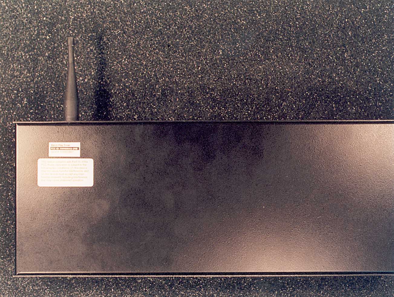
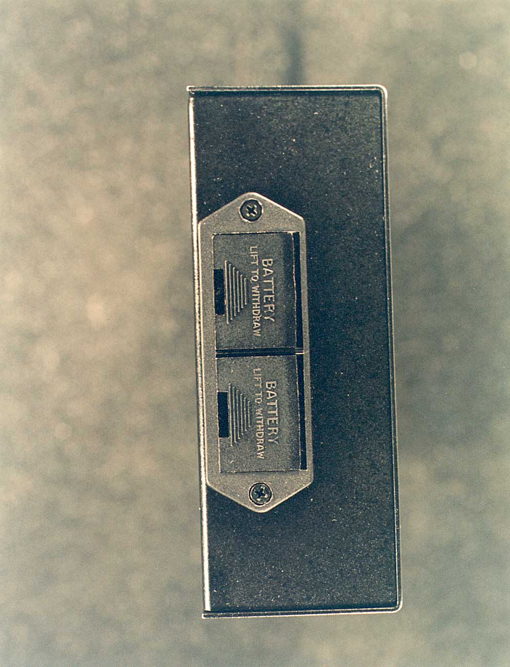
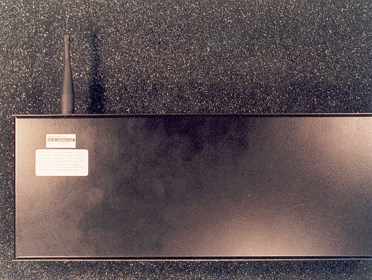
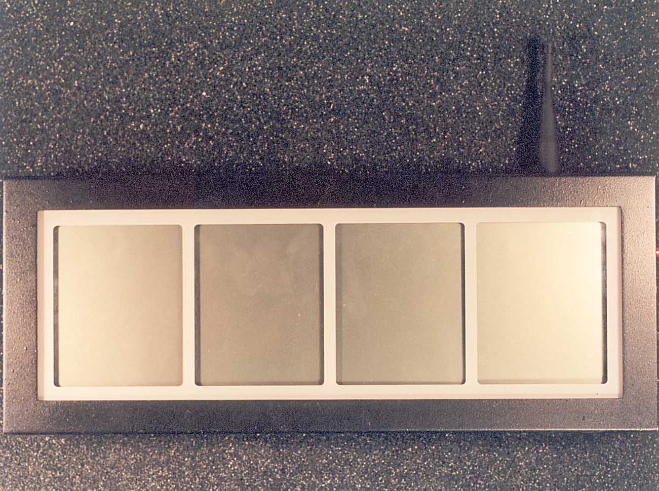
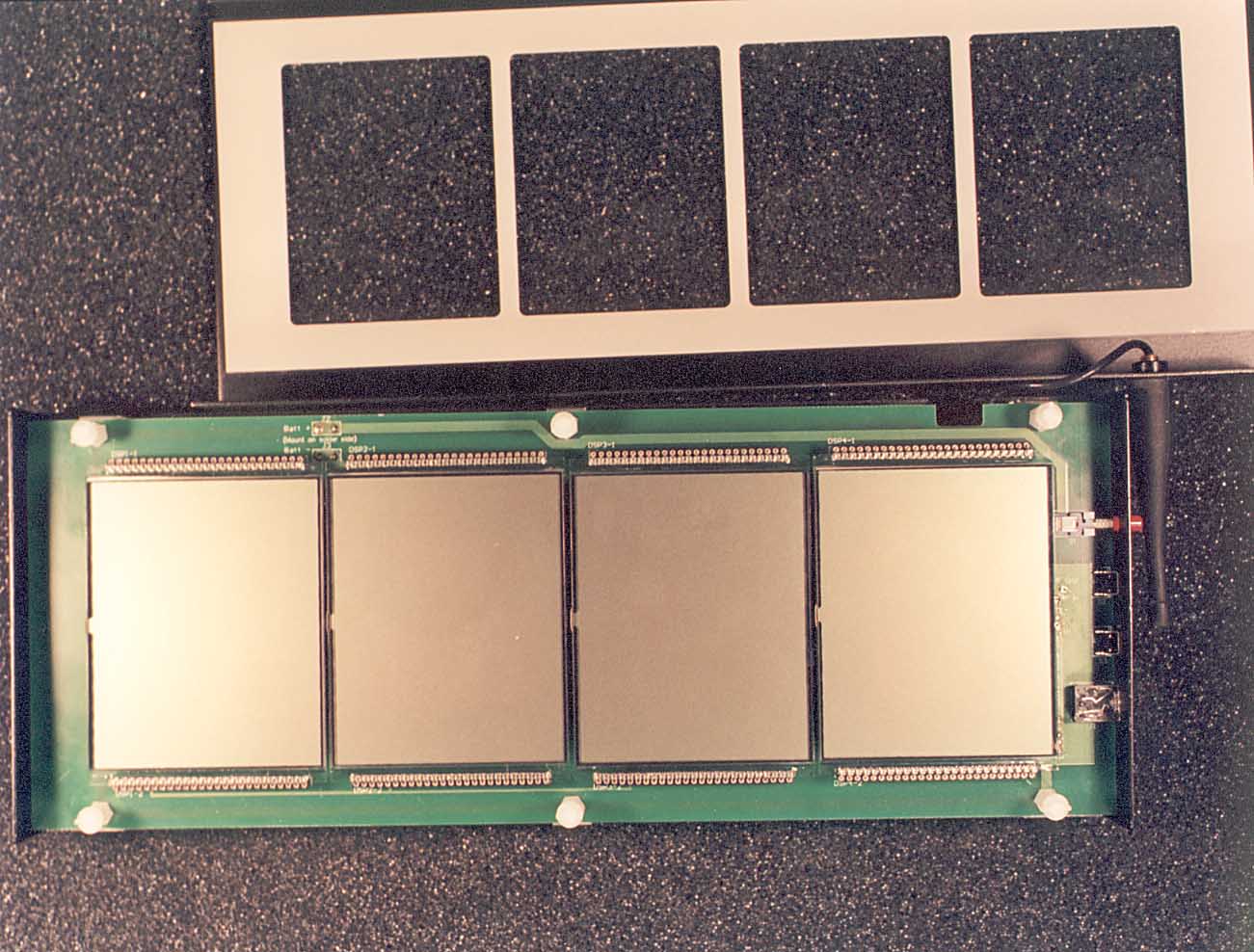
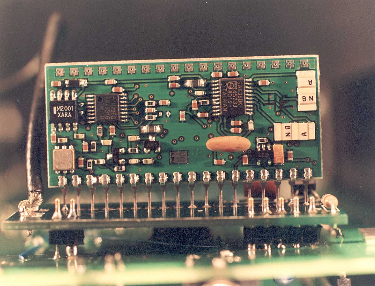
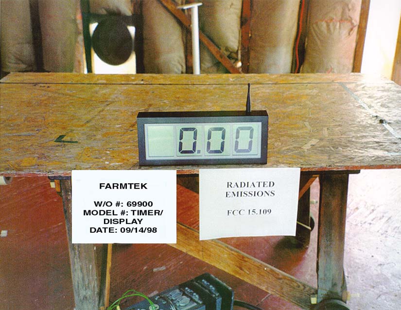
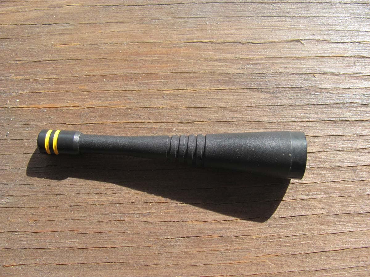
Match Play Timer RF OverviewFarmTek, Inc. 07/13/01Page 1 Introduction The Match Play Timer is used to time track and field events which start at point “A” and finish at point “B” (such as a 100 yard dash). A photosensor pair is used at the starting point to automati- cally start timing when a runner crosses the starting line. A second photosensor pair is used at the finish line to automatically stop timing when the runner crosses the finish line. Timing is per- formed by a unit separate from the photosensors. To make setup and operation simple, all units operate from internal, disposable batteries and a one-way wireless link is used from the photo- sensor to the timing unit to signal the timer to start or stop. Wireless Radio Link The wireless radio link used in the Match Play Timer is a one-way link from each photo-receiver to the timing/display unit. The wireless link operates under FCC regulations Part 15, Section 249: • Operating frequency is selectable on the following eight channels: ChannelFrequencyChannelFrequency 0903.34912.3 1906.35915.3 2907.86919.8 3909.37921.3 • Both the radio transmitter and receiver are frequency synthesized with a crystal stabilized phase locked loop (PLL) to eliminate the need for periodic adjustment or tuning. • To improve interference rejection in noisy radio environments, FSK (Frequency Shift Keying) modulation is used instead of AM or OOK (On/Off Keying). • Full ¼ wave whips are used on both the transmitter and receiver. Match Play Timer RF OverviewFarmTek, Inc. 07/13/01Page 2 When the light beam is broken, the photo-receiver transmits an identifying message to the Tim- ing Unit to indicate that the beam was broken. The message is repeated 28 times on one channel and then 28 times again on a second channel (425 ms on each channel for a total of 850 ms transmission time). Photo-Receiver (contains RF Transmitter) The photo-receiver detects the infrared beam of light that is emitted by the opposing photo- transmitter. When the photo-receiver detects a broken beam, it transmits a message to the main timing unit via a one-way radio link. The following table outlines specifications particular to the photo-receiver: PackagingPlastic case approximately 2.5 x 3.8 x 1.0 inches with an easily accessible battery compartment. PowerA 9 volt alkaline battery provides a minimum of 80 hours of operation. Radio Link8 channel, 900 Mhz, FSK transmitter. A ¼ wave, flexible antenna exits through the top of the case. The transmitter activates whenever the unit de- tects the infrared beam has been broken. Timing / Display Unit (contains RF Receiver) The main timing unit functions as both the timing and display mechanism. Time is displayed on a four digit, liquid crystal display (LCD), with 3 inch tall digits. The timing unit is automatically started and stopped by the start and finish line photosensors via a one-way radio link to the tim- ing unit. PackagingMetal case approximately 14 x 6 x 2 inches with an easily accessible battery compartment. PowerThe unit is powered by two 9 volt alkaline batteries. The batteries provide a minimum of 80 hours of operation. Radio Link8 channel, 900 Mhz, FSK receiver. A ¼ wave, flexible antenna exits through the top of the case.
Test Report
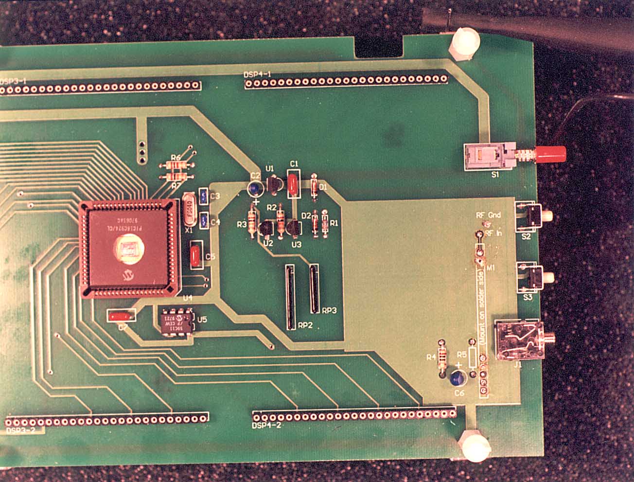
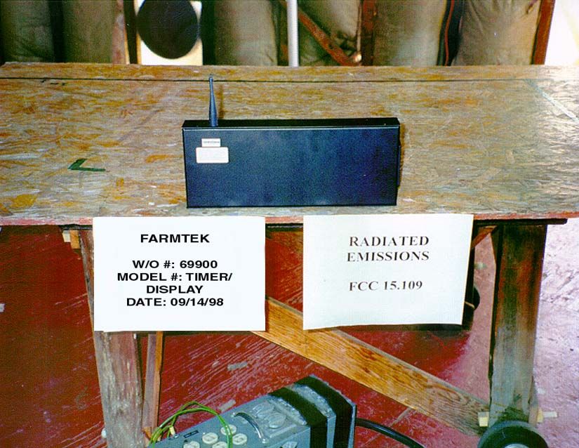
Page 1 of 17 Report No: FB98-129 CERTIFICATION TEST REPORT FOR THE TIMING DEVICE, MATCH PLAY TIMER FCC PART 15, SUBPART B CLASS B COMPLIANCE DATE OF ISSUE: AUGUST 27, 1998 PREPARED FOR: FarmTek, Inc. 5113 Heritage Sachse, TX 75048 P.O. No: Check #8155 W.O. No: 68,604 PREPARED BY: Monika Lopez CKC Laboratories, Inc. 5473A Clouds Rest Mariposa, CA 95338 Date of test: September 14, 1998 Report No: FB98-129 DOCUMENTATION CONTROL: _____________________________ Tracy Phillips Documentation Control Supervisor CKC Laboratories, Inc. APPROVED BY: _____________________________ Dennis Ward Director of Laboratories CKC Laboratories, Inc. This report contains a total of 17 pages and may be reproduced in full only. Partial reproduction may only be done with the written consent of CKC Laboratories, Inc. Page 2 of 17 Report No: FB98-129 TABLE OF CONTENTS Administrative Information..........................................................................................3 Summary Of Results....................................................................................................4 Equipment Under Test (EUT) Description...................................................................4 Measurement Uncertainty............................................................................................4 Peripheral Devices.......................................................................................................4 Report Of Measurements.............................................................................................5 Table 1: Six Highest Radiated Emission Levels................................................5 Table A : List Of Test Equipment................................................................................6 EUT Setup...................................................................................................................7 Test Instrumentation And Analyzer Settings................................................................7 Table B : Analyzer Bandwidth Settings Per Frequency Range..........................7 Spectrum Analyzer Detector Functions.............................................................8 Peak......................................................................................................8 Quasi-Peak...........................................................................................8 Average................................................................................................8 Test Methods...............................................................................................................9 Radiated Emissions Testing..............................................................................9 Sample Calculations.....................................................................................................10 Appendix A : Information About The Equipment Under Test......................................11 I/O Ports...........................................................................................................12 Crystal Oscillators............................................................................................12 Printed Circuit Boards......................................................................................12 Required EUT Changes To Comply.................................................................12 Photograph Showing Radiated Emissions.........................................................13 Photograph Showing Radiated Emissions.........................................................14 Photograph Showing Radiated Emissions.........................................................15 Appendix B : Measurement Data Sheets......................................................................16 Page 3 of 17 Report No: FB98-129 CKC Laboratories, Inc. has Certificates of Accreditation from the following agencies: DATech (Germany); A2LA (USA); FCC (USA); VCCI (Japan); BCIQ (Taiwan); HOKLAS (Hong Kong). CKC Laboratories, Inc. has Letters of Acceptance through an MRA for the following agencies: ACA/NATA (Australia); SABS (South Africa); SWEDAC (Sweden); TUV Rheinland-Germany; TUV Rheinland- Korea; TUV Rheinland-Russia; Radio Communication Agency (RA); NEMKO (Norway). ADMINISTRATIVE INFORMATION DATE OF TEST: September 14, 1998 PURPOSE OF TEST: To demonstrate the compliance of the Timing Device, Match Play Timer, with the FCC Part 15, Subpart B requirements for Class B devices. MANUFACTURER: FarmTek, Inc. 5113 Heritage Sachse, TX 75048 REPRESENTATIVE: Mike Douglas TEST LOCATION: CKC Laboratories, Inc. 5473A Clouds Rest Mariposa, CA 95338 TEST PERSONNEL: Skip Doyle TEST METHOD: ANSI C63.4 1992 FREQUENCY RANGE TESTED: 30 MHz - 10 GHz EQUIPMENT UNDER TEST:Timing Device Manuf: FarmTek, Inc. Model: Match Play Timer Serial: 10000019807 FCC ID: NWNMI052-2RB Page 4 of 17 Report No: FB98-129 SUMMARY OF RESULTS The FarmTek, Inc. Timing Device, Match Play Timer, was tested in accordance with ANSI C63.4 1992 for compliance with the Class B requirements of Part 15, Subpart B of the FCC Rules. As received, the above equipment was found to be fully compliant with the Class B limits of FCC Part 15, Subpart B for radiated emissions. EQUIPMENT UNDER TEST (EUT) DESCRIPTION Electronic timer for track events (RF receiving unit) with remote photo-sensors for automatic start/stop (RF transmitting unit). MEASUREMENT UNCERTAINTY Associated with data in this report is a ±4dB measurement uncertainty. PERIPHERAL DEVICES The EUT was not tested with peripheral devices. Page 5 of 17 Report No: FB98-129 REPORT OF MEASUREMENTS The following Table 1 reports the six highest radiated emissions levels recorded during the tests performed on the Timing Device, Match Play Timer. The data sheet from which this table was compiled are contained in Appendix B. Table 1: Six Highest Radiated Emission Levels METERCORRECTION FACTORSCORRECTEDSPEC FREQUENCYREADINGAntAmpCableDistREADINGLIMITMARGINNOTES MHzdBμVdBdBdBdBdBμ…
Text truncated - open the document above for the full version.
Contact Information
Applicant
Mike Douglas(President)
Technical Contact
CKC Laboratories, Inc.Tracy Phillips
[email protected]209-966-4257
5473A Clouds Rest · Mariposa, California · United States
Non-Technical Contact
CKC Laboratories, Inc.Joyce Walker
[email protected]209-966-5240
Test Firm
CKC Laboratories, Inc.Steve Behm
Technical Specifications
| # | Rule Parts | Frequency Range | Power Output |
|---|---|---|---|
| 1 | 15B | 903.3 MHz - 921.3 MHz | - |
Other Applications from FarmTek Inc
NWNMI043
Feb 23, 2011Polaris Timer Console
Equipment Class
DXT - Part 15 Low Power Transceiver, Rx Verified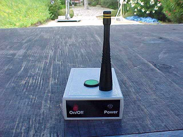
NWNMI046
Jul 19, 2005Wireless Photo-Receiver
Equipment Class
DXX - Part 15 Low Power Communication Device Transmitter
NWNM104X
Jan 18, 2005Timer Console
Equipment Class
DXX - Part 15 Low Power Communication Device Transmitter
NWNM106X
Mar 15, 2004Light Curtain
Equipment Class
DXX - Part 15 Low Power Communication Device Transmitter
NWNMI050-2RB
Oct 01, 1998DXX - Part 15 Low Power Communication Device Transmitter
Equipment Class
DXX - Part 15 Low Power Communication Device Transmitter