NY5MAA01Remote Pendant for healthcare system
Mytrex Inc.
Click to zoom
Application Details
- Equipment Class
- DSC - Part 15 Security/Remote Control Transmitter
- Date of Grant
- May 21, 2015
- Application Purpose
- Original Equipment
- Date of Application
- May 21, 2015
- Equipment Note
- Remote Pendant for healthcare system
- Frequency Range
- 417.95000000 - 417.95000000
- Company
- Mytrex Inc.
- Country
- United States
Documents & Files
Document Text
Text extracted from the exhibit documents filed with the FCC. Open a document above to read the original.
Users Manual
myActiveAlert User Instructions Version 1.0b April 27, 2015 Mytrex, Inc. 10321 Beckstead Lane South Jordan, UT 84095 2 | P a g e Introduction The myActiveAlert is a personal emergency response pendant manufactured by Mytrex, Inc. that features patented and clinically validated automatic fall detection algorithms developed by BioSensics LLC. Additional key features and benefits of the BioSensics technology include patented algorithms designed to reduce false alarms, monitoring the number of steps taken, and notifying providers when the pendant is not worn by the subscriber. The myActiveAlert also incorporates a water resistant HELP button to request help at the press of a button. The myActiveAlert may be operated in one of two modes: Basic and Enhanced. In either mode the device may be programmed to transmit a periodic supervisory or heartbeat signal to the Mytrex personal emergency response system (PERS); such as an MXD or MXD3G. This transmission enables the base unit to monitor the radio link, battery condition and activity level of the user. Detecting a Fall When the algorithms determine a fall may have occurred, the LED begins to flash slowly. A few seconds later the LED will flash quicker. Within a few seconds the LED will turn on steady and a FALL ALERT signal is transmitted to the PERS. A red LED indicates low battery and green indicates a good battery. During the FALL ALERT signal transmission, the LED will always illuminate steady for approximately two seconds. Note: Due to the many types of falls that can occur, the user should always press the HELP button whenever help is needed and not rely solely upon the determination of the fall detection algorithms. See “Other Notices”. Sending a HELP ALERT Signal To send a HELP ALERT signal to the PERS, press and release the HELP button on the face of the myActiveAlert. The signal for help is transmitted as soon as the button is pressed and will continue to transmit for an additional two seconds after releasing the HELP button. The LED will illuminate for the entire duration of the signal transmission according to Table 1. Clearing the FALL ALERT When the algorithms determine a fall may have occurred, the LED begins to flash slowly. While the LED is flashing, the algorithms continue to monitor movement. Transmission of the FALL ALERT signal is prohibited and the LED is turned off if the algorithms determine the user has taken three steps. Once the LED turns on steady, the FALL ALERT signal cannot be cancelled. Battery Monitoring The myActiveAlert periodically monitors the internal battery voltage. If the voltage is below a certain threshold, a LOW BATTERY signal is transmitted to the PERS. Once a low battery is reported, the myActiveAlert should be replaced within two weeks. 3 | P a g e Button Only Mode The myActiveAlert is shipped in the Button Only Mode. Movements are not monitored (fall detection disabled) in this mode which greatly extends the battery life. However, pressing the HELP button on the face of the myActiveAlert will cause a HELP ALERT signal to be transmitted. The signal is transmitted for approximately two seconds after the button is released and the LED flashes slowly. Green indicates a good battery and red indicates a low battery. Basic Mode This mode of operation includes the functionality of the HELP button, automatic fall detection, battery monitoring, and if desired, supervisory or heartbeat transmissions. To enable the Basic Mode of operation, the HELP button must be pressed 7 times within a 3-second period. Once the Basic mode is enabled, the LED will illuminate steadily when the HELP button is pressed as indicated in Table 1. NOTE: If supervisory (heartbeat) transmissions are enabled, it is important that your dealer activates the supervisory mode in the PERS as well. Enhanced Mode This mode includes all of the same functionalities of the basic mode. In addition, the activity of the subscriber (number of steps taken) and non-compliance alert signals (subscriber not wearing the myActiveAlert) may be transmitted to the PERS. To enable the Enhanced Mode of operation, the HELP button must be pressed 5 times within a 3- second period. Once the Enhanced mode is enabled, the LED will flash quickly when the HELP button is pressed as indicated in Table 1. NOTE: If supervisory (heartbeat) transmissions are enabled, it is important that your dealer activates the supervisory mode in the PERS as well. LEDs The myActiveAlert has a red and a green LED to indicate various modes of operation as shown in Table 1. The indicated LED status is applicable to both the Basic and Enhanced modes of operation. Table 1: LED Status definitions Green Battery Good Steady Basic Mode Flash Quickly Enhanced Mode Red Battery Low Steady Basic Mode Flash Quickly Enhanced Mode Battery Life Expectancy The battery of the myActiveAlert is not replaceable. The life expectancy is variable and is dependent upon which features are enabled and the operating parameters chosen. In addition, the higher the activity level of the subscriber, the lower the battery life expectancy. 4 | P a g e Specifications Dimension: 2.165” x 1.468” x 0.603” RF Transmission Frequency: 418 MHz Operating Temperature: -10ºC to 60ºC Battery Type: CR2450 Lithium Battery Life: 1 year or more (2 years in Basic non-supervised mode) Battery Voltage: 3.0V FCC ID: NY5MAA01 IC: 9663A-MAA01 FCC and Industry Canada Notice This device complies with part 15 of the FCC Rules and Industry Canada license-exempt RSS standard(s). Operation is subject to the following two conditions: (1) this device may not cause harmful interference, and (2) this device must accept any interference received, including interference that may cause undesired operation. Le présent appareil est conforme aux CNR d’Industrie Canada applicables aux appareils radio exempts de licence. L’exploitation est autorisée aux deux conditions suivantes: (1) l’appareil ne doit pas produire de brouillage, et (2) l’ut…
Text truncated - open the document above for the full version.
External Photos
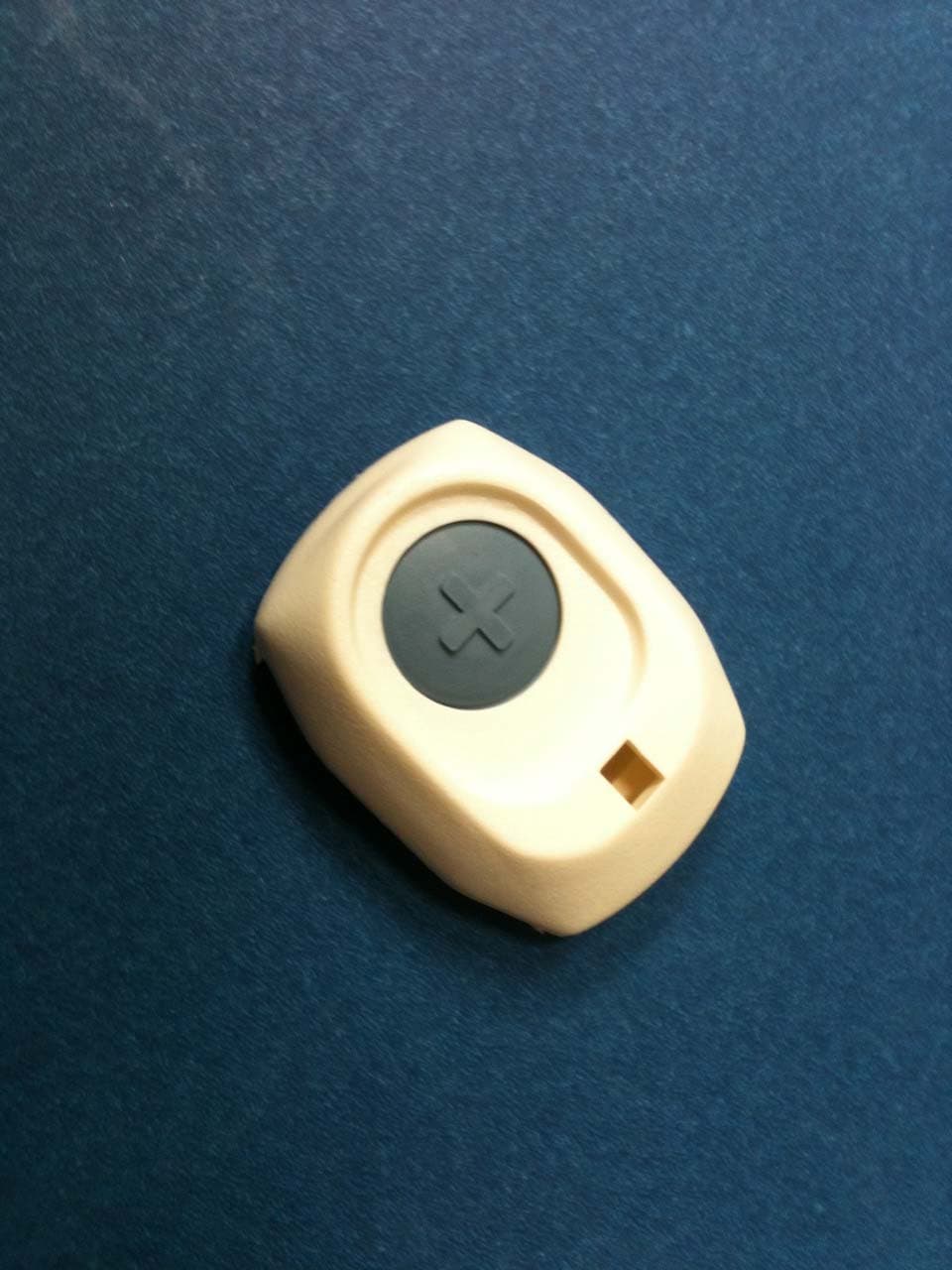
External Photographs Front View of the EUT Back View of the EUT
ID Label/Location Info
Sample Drawing of label to be placed on the bottom of the myActiveAlert pendant: Dimensions approximately 0.7” x 0.48” F Model: myActiveAlert FCC ID: NY5MAA01 IC: 9663A-MAA01 See Manual S/N:XXXXXX
Internal Photos
Internal Photographs View of the Front Side of the PCB View of the Back Side of the PCB
Test Report
Nemko-CCL, Inc. 1940 West Alexander Street Salt Lake City, UT 84119 801-972-6146 Test Report Certification Test Of: myActiveAlert Test Specifications: FCC Part 15, Subpart C FCC ID: NY5MAA01 Test Report Serial No: 280149-4.1 Applicant: Mytrex, Inc. 10321 South Beckstead Lane South Jordan, UT 84095 U.S.A Date of Test: March 5, 2015 Report Issue Date: May 7, 2015 Accredited Testing Laboratory By: NVLAP Lab Code 100272‐0 Nemko-CCL, Inc. TEST REPORT: 280149-4.1 REPORT ISSUE DATE: 05/07/2015 Page 2 of 28 TRF-15.231SUBC Issue 4 March. 2015 CERTIFICATION OF ENGINEERING REPORT This report has been prepared by Nemko-CCL, Inc. to document compliance of the device described below with the certification requirements of FCC Part 15, Subpart C. This report may be reproduced in full. Partial reproduction of this report may only be made with the written consent of the laboratory. The results in this report apply only to the sample tested. - Applicant: Mytrex, Inc. - Manufacturer: Mytrex, Inc. - Brand Name: Mytrex - Model Number: myActiveAlert - FCC ID: NY5MAA01 On this 7 th day of May 2015, I, individually and for Nemko-CCL, Inc., certify that the statements made in this engineering report are true, complete, and correct to the best of my knowledge, and are made in good faith. Although NVLAP has accredited the Nemko-CCL, Inc. EMC testing facilities, this report must not be used to claim product certification, approval, or endorsement by NVLAP, NIST, or any agency of the federal government. Nemko-CCL, Inc. Tested by: Norman P. Hansen Test Technician Reviewed by: Thomas C. Jackson Certification Manager Nemko-CCL, Inc. TEST REPORT: 280149-4.1 REPORT ISSUE DATE: 05/07/2015 Page 3 of 28 TRF-15.231SUBC Issue 4 March. 2015 TABLE OF CONTENTS PAGE SECTION 1.0 CLIENT INFORMATION .................................................................................4 SECTION 2.0 EQUIPMENT UNDER TEST (EUT)..................................................................5 SECTION 3.0 TEST SPECIFICATION, METHODS & PROCEDURES .............................6 SECTION 4.0 OPERATION OF EUT DURING TESTING..................................................10 SECTION 5.0 SUMMARY OF TEST RESULTS ...................................................................11 SECTION 6.0 MEASUREMENTS, EXAMINATIONS AND DERIVED RESULTS ..........12 APPENDIX 1 TEST PROCEDURES AND TEST EQUIPMENT .........................................19 APPENDIX 2 PHOTOGRAPHS ................................................................................................21 Nemko-CCL, Inc. TEST REPORT: 280149-4.1 REPORT ISSUE DATE: 05/07/2015 Page 4 of 28 TRF-15.231SUBC Issue 4 March. 2015 SECTION 1.0 CLIENT INFORMATION 1.1 Applicant: Company Name: Mytrex, Inc. 10321 South Beckstead Lane South Jordan, UT 84095 U.S.A Contact Name: Richard Bangerter Title: President 1.2 Manufacturer: Company Name: Mytrex, Inc. 10321 South Beckstead Lane South Jordan, UT 84095 U.S.A Contact Name: Richard Bangerter Title: President Nemko-CCL, Inc. TEST REPORT: 280149-4.1 REPORT ISSUE DATE: 05/07/2015 Page 5 of 28 TRF-15.231SUBC Issue 4 March. 2015 SECTION 2.0 EQUIPMENT UNDER TEST (EUT) 2.1 Identification of EUT: Brand Name: Mytrex Model Number: myActiveAlert Serial Number: None Dimensions: 2.165 cm x 1.468 cm x 0.603 cm 2.2 Description of EUT: myActiveAlert is a device worn by an individual that is used to notify a monitoring system that assistance is needed. myActiveAlert has a 418 MHz transmitter that uses Manchester encoding. It is powered by a CR2450 battery and uses a trace as the antenna. This report covers the transmitter circuitry of the device subject to FCC Part 15, Subpart C. The circuitry of the device, subject to FCC Part 15, Subpart B is covered in Nemko-CCL, Inc. report 280149-9. 2.3 EUT and Support Equipment: Brand Name Model Number Serial Number FCC ID Number or Compliance Description Name of Interface Ports / Interface Cables BN: Mytrex MN: myActiveAlert SN: None NY5MAA01 Security/Remot e control transmitter See Section 2.4 2.4 Interface Ports on EUT: There are no interface ports on the EUT. 2.5 Modification Incorporated/Special Accessories on EUT: The following modifications were made to the EUT by the Client during testing to comply with the specification. This report is not complete without an accompanying signed attestation, that the product will have all of the documented modifications incorporated into the product when manufactured and placed on the market. 1. The transmitter filter circuit had 0 ohms resistors placed by 2 – 12 nH inducotrs and the unused pads in the filter circuit loaded with 4 – 3.0 pF capacitors. Nemko-CCL, Inc. TEST REPORT: 280149-4.1 REPORT ISSUE DATE: 05/07/2015 Page 6 of 28 TRF-15.231SUBC Issue 4 March. 2015 SECTION 3.0 TEST SPECIFICATION, METHODS & PROCEDURES 3.1 Test Specification: Title: FCC PART 15, Subpart C (47 CFR 15) Section 15.203, Section 15.207, and Section 15.231 Periodic operation in the band 40.66-40.70 MHz and above 70 MHz Purpose of Test: The tests were performed to demonstrate initial compliance. 3.2 Methods & Procedures: 3.2.1 §15.203 An intentional radiator shall be designed to ensure that no antenna other than that furnished by the responsible party shall be used with the device. The use of a permanently attached antenna or of an antenna that uses a unique coupling to the intentional radiator shall be considered sufficient to comply with the provisions of this Section. The manufacturer may design the unit so that a broken antenna can be replaced by the user, but the use of a standard antenna jack or electrical connector is prohibited. This requirement does not apply to carrier current devices or to devices operated under the provisions of Sections 15.211, 15.213, 15.217, 15.219, or 15.221. Further, this requirement does not apply to intentional radiators that must be professionally installed, such as perimeter protection systems and some field disturbance sensors, or to other intentional radiators which, in accordance…
Text truncated - open the document above for the full version.
Test Setup Photos
Setup Photographs Front View Radiated Disturbance Worst Case Configuration – Vertical Back View Radiated Disturbance Worst Case Configuration – Vertical Back View Radiated Disturbance – On Edge Configuration Front View Radiated Disturbance – Horizontal Configuration
Contact Information
Applicant
Richard M Bangerter(President)
Test Firm
Nemko-CCL incThomas Jackson
Technical Specifications
| # | Rule Parts | Frequency Range | Power Output |
|---|---|---|---|
| 1 | 15.231 | 417.95 MHz - 417.95 MHz | - |
Other Applications from Mytrex Inc.
NY5RA3TX
Dec 21, 2010Remote pendant for healthcare system
Equipment Class
DSC - Part 15 Security/Remote Control Transmitter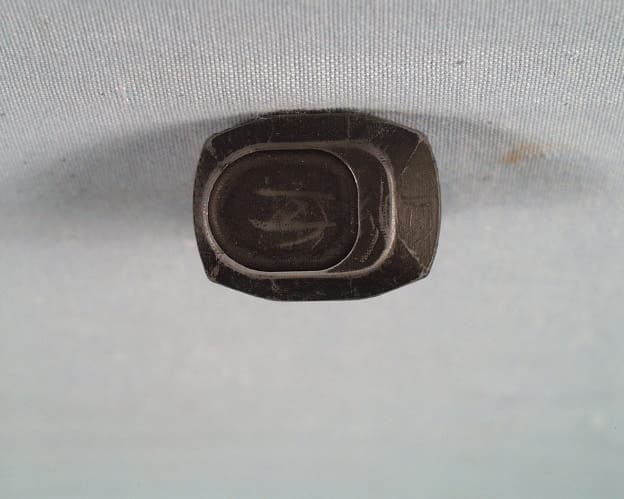
NY5RA3T
Aug 09, 1998Medical Emergency Transmitter
Equipment Class
DXX - Part 15 Low Power Communication Device Transmitter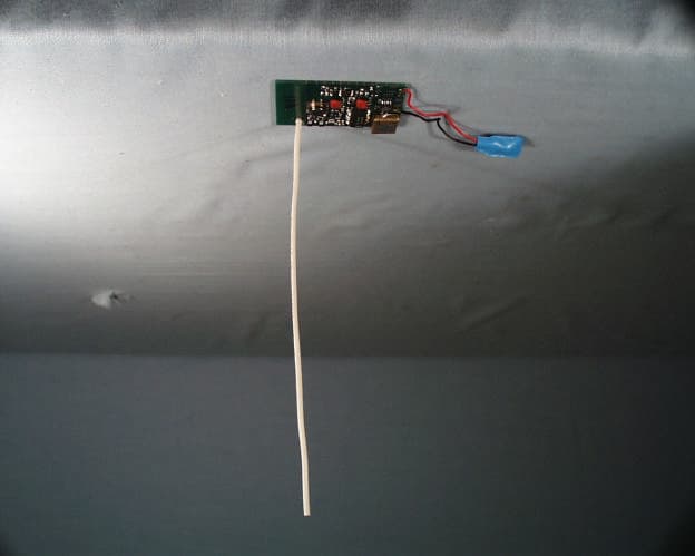
NY5RA3R
Aug 04, 1998Receiver for Medical Emergency Application
Equipment Class
CYY - Communications Receiver used w/Pt 15 Transmitter