NY5RA3TMedical Emergency Transmitter
Mytrex Inc.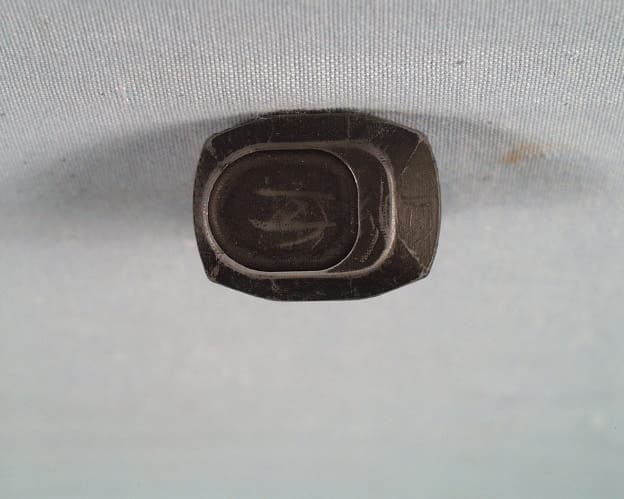
Click to zoom
Application Details
- Equipment Class
- DXX - Part 15 Low Power Communication Device Transmitter
- Date of Grant
- Aug 09, 1998
- Application Purpose
- Original Equipment
- Date of Application
- Jul 06, 1998
- Equipment Note
- Medical Emergency Transmitter
- Frequency Range
- 418.00000000 - 418.00000000
- Company
- Mytrex Inc.
- Country
- United States
Documents & Files
Document Text
Text extracted from the exhibit documents filed with the FCC. Open a document above to read the original.
Users Manual
COMMUNICATION CERTIFICATION LABORATORYTEST REPORT: 73-6557 FCC ID: NY5RA3T Exhibit 8: User’s Manual RA3T TRANSMITTER GENERAL DESCRIPTION: RA3T transmitter is designed to send a coded transmission to any standard 418 MHz ASK receiver manufactured by Mytrex, Inc. The RA3T may be worn around the neck or on the wrist and is activated by pressing the button on the front of the transmitter. When the RA3T is activated, the LED on the front is i11ununated to provide an indication of the battery status. A green LED indicates the battery voltage is above 4.5 volts. A red LED indicates the battery voltage is below 4.5 volts. Typically the transmitter will function another year depending on the frequency and length of use each day. An automatic telephone dialer used in the medical industry is a typical application that might utilize an RA3T transmitter and an RA3R series receiver. The receiver would be used to activate the dialer to begin calling for help in response to a user pressing the Panic button on the RA3T. NOTES: The RA3T transmitter is designed and tested to high specific standards. However, due to laws of physics, vagaries of radio transmissions and the limited output power allowed by the FCC, there are some limitations to be considered: · All receivers may be blocked by radio signals occurring on or near their operating frequencies, regardless of the code selected. · A receiver can only respond to one transmitter signal at a time regardless of the number of codes in the Valid Code List. Wireless equipment should be tested regularly to determine if there are sources of interference and to protect against faults. . NOTIFICATIONS: · This device complies with part 15 of the FCC Rules. Operation is subject to the following two conditions: (1) this device may not cause harmful interference, and (2) this device must accept any interference received, including interference that may cause undesired operation. These limits are designed to provide reasonable protection against harmful interference in a residential installation. This equipment generates, uses and can radiate radio frequency energy and, if not installed and used in accordance with the instructions, may cause harmful interference to radio communications. However, there is no guarantee that interference will not occur in a particular installation. If this equipment does cause harmful interference to radio or television reception, which can be determined by turning the equipment off and on, the user is encouraged to try to correct the interference by one or more of the following measures: · Reorient or relocate the receiving antenna. · Increase the separation between the equipment and receiver. · Comnect the equipment into an outlet on a circuit different from that to which the receiver is connected. COMMUNICATION CERTIFICATION LABORATORYTEST REPORT: 73-6557 FCC ID: NY5RA3T · Consult the dealer or an experienced radio/TV technician for help. Important: Changes or modifications to this unit not expressly approved by the responsible party for compliance may void the user's authority to operate the equipment. Infrequently used radio links should be tested regularly to protect against undetected interference or fault. A general knowledge of radio and its vagaries should be gained prior to acting as a wholesale distributor or dealer, and these facts should be communicated to the ultimate user.
Cover Letter(s)
COMMUNICATION CERTIFICATION LABORATORYTEST REPORT: 73-6557 FCC ID: NY5RA3T Exhibit 13: Cover Letters July 6, 1998 FEDERAL COMMUNICATIONS COMMISSION Equipment Authorization Division 7435 Oakland Mills Road Columbia, MD 21046 To Whom It May Concern: Enclosed is a FCC Part 15 Certification application for the Mytrex Inc. Model RA3T, FCC ID NY5RA3T. Please let me know if I can be of further assistance. Sincerely yours, COMMUNICATION CERTIFICATION LABORATORY Joseph W. Jackson V.P. Marketing COMMUNICATION CERTIFICATION LABORATORYTEST REPORT: 73-6557 FCC ID: NY5RA3T
External Photos
COMMUNICATION CERTIFICATION LABORATORYTEST REPORT: 73-6557 FCC ID: NY5RA3T Exhibit 3: Photographs of Overall Appearance Front View of the RA3T Back View of the RA3T
ID Label/Location Info
COMMUNICATION CERTIFICATION LABORATORYTEST REPORT: 73-6557 FCC ID: NY5RA3T Exhibit 1: FCC ID Label Equipment Identification Label The label of the Mytrex Inc. Model RA3T will be place on the RA3T as shown is the photograph on the following page. Photograph showing label placement
Internal Photos
COMMUNICATION CERTIFICATION LABORATORYTEST REPORT: 73-6557 FCC ID: NY5RA3T Exhibit 9: Internal Photographs Component Side COMMUNICATION CERTIFICATION LABORATORYTEST REPORT: 73-6557 FCC ID: NY5RA3T Solder Side
Test Report
COMMUNICATION CERTIFICATION LABORATORYTEST REPORT: 73-6557 FCC ID: NY5RA3T Exhibit 6: Test Report TEST REPORT FROM: COMMUNICATION CERTIFICATION LABORATORY 1940 W. Alexander Street Salt Lake City, Utah 84119-2039 Type of Report: Certification TEST OF: RA3T FCC ID: NY5RA3T To FCC PART 15, Subpart C Section 15.231 Test Report Serial No: 73-6557 Applicant: Mytrex Inc. 7050 Union Park Avenue Suite 590 Midvale, UT 84047 Date of Test: June 16, 1998 Issue Date: July 6, 1998 COMMUNICATION CERTIFICATION LABORATORYTEST REPORT: 73-6557 FCC ID: NY5RA3T CERTIFICATION OF ENGINEERING REPORT This report has been prepared by Communication Certification Laboratory to determine compliance of the device described below with the notification requirements of FCC Part 15, Subpart C Section 15.231. This report may be reproduced in full, partial reproduction may only be made with the written consent of the laboratory. The results in this report apply only to the sample tested. -Applicant:Mytrex Inc. - Manufacturer:Mytrex Inc. -Brand Name:RESCUE ALERT -Model Number:RA3T -FCC ID:NY5RA3T On this 6 th day of July 1998, I, individually, and for Communication Certification Laboratory, certify that the statements made in this engineering report are true, complete, and correct to the best of my knowledge, and are made in good faith. Although NVLAP has recognized that the Communication Certification Laboratory EMC testing facilities are in good standing, NVLAP does not endorse the product described in this report. COMMUNICATION CERTIFICATION LABORATORY Checked by: Anh T. Wride Telecom Engineering Director Tested by: Roger J. Midgley EMC Engineering Manager COMMUNICATION CERTIFICATION LABORATORYTEST REPORT: 73-6557 FCC ID: NY5RA3T SECTION 1.0 CLIENT INFORMATION 1.1 Client Information: Company Name: Mytrex Inc. 7050 Union Park Avenue Suite 590 Midvale, UT 84047 Contact Name:Richard M. Bangerter Title:President Department: COMMUNICATION CERTIFICATION LABORATORYTEST REPORT: 73-6557 FCC ID: NY5RA3T SECTION 2.0 EQUIPMENT UNDER TEST (EUT) 2.1 Identification of EUT: Trade Name:RESCUE ALERT Model Name or Number:RA3T Serial Number:N/A Options Fitted:N/A Country of Manufacture:U.S.A. 2.2 Description of EUT: The RA3T transmitter is designed to send a coded transmission to any standard 418 MHz ASK receiver manufactured by Mytrex, Inc. The RA3T may be worn around the neck or on the wrist and is activated by pressing the button on the front of the transmitter. When the RA3T is activated, the LED on the front is i11ununated to provide an indication of the battery status. A green LED indicates the battery voltage is above 4.5 volts. A red LED indicates the battery voltage is below 4.5 volts. Typically the transmitter will function another year depending on the frequency and length of use each day. An automatic telephone dialer used in the medical imdustry is a typical application that might utilize an RA3T transmitter and an RA3R series receiver . The receiver would be used to activate the dialer to begin calling for help in response to a user pressing the Panic button on the RA3T 2.3 Modification Incorporated/Special Accessories on EUT: There were no modifications or special accessories required to comply with the specification. COMMUNICATION CERTIFICATION LABORATORYTEST REPORT: 73-6557 FCC ID: NY5RA3T SECTION 3.0 TEST SPECIFICATION, METHODS & PROCEDURES 3.1 Test Specification: Title:FCC PART 15, Subpart C (47 CFR 15). Section 15.231 Periodic operation in the band 40.66-40.70 MHz and above 70 MHz. Purpose of Test: The tests were performed to demonstrate Initial compliance. 3.2 Methods & Procedures: 3.2.1 '' 15.231 (a) The provision of this section are restricted to periodic operation within the band 40.66-40.70 MHz and above 70 MHz. Except as chow in paragraph (e) of this section, the intentional radiator is restricted to the transmission of a control signal such as those used with alarm systems, door openers, remote switches, etc. Radio control of toys in not permitted. Continuous transmissions, such as voice or video, and data transmissions are not permitted. The prohibition against data transmissions does not preclude the use of recognition codes. Those codes are used to identify the sensor that is activated or to identify the particular component as being part of the system. The following conditions shall be met to comply with the provisions for this periodic operation: (1) A manually operated transmitter shall employ a switch that will automatically deactivate the transmitter within not more than 5 seconds of being released. (2) A transmitter activated automatically shall cease transmission within 5 seconds after activation. (3) Periodic transmissions at regular predetermined intervals are not permitted. However, polling or supervision transmission to determine system integrity of transmitters used in security or safety applications are allowed if the periodic rate of transmission does not exceed one transmission of not more than one second duration per hour for each transmitter. (4) Intentional radiators which are employed for radio control purposes during emergencies involving fire, security, and safety COMMUNICATION CERTIFICATION LABORATORYTEST REPORT: 73-6557 FCC ID: NY5RA3T of life, when activated to signal an alarm, may operated during the pendency of the alarm condition. (b) In addition to the provisions of ' 15.205, the field strength of emission from intentional radiators operated under this section shall not exceed the following: Fundamental frequency (MHz) Field strength of fundamental (microvolts/meter) Field strength of spurious emissions (microvolts/meter) 40.66 - 40.702,250225 70 -1301,250125 130 - 1741,250 to 3,750 **125 to 375 ** 174 - 2603,750375 260 - 4703,750 to 12,500 **375 to 1,250 ** Above 47012,5001,250 ** Linear interpolations (1) the above field strength limits are specified at a distance of 3 meters. The tighter limits apply at the band edges. (2) Intentional radiators operating under the provisions of thi…
Text truncated - open the document above for the full version.
Test Setup Photos
COMMUNICATION CERTIFICATION LABORATORYTEST REPORT: 73-6557 FCC ID: NY5RA3T Exhibit 7: Test Set-Up Photographs
Contact Information
Applicant
Richard M Bangerter(President)
Technical Contact
Communication Certification LaboratoryRoger J Midgley
[email protected](801) 972-6146
1940 W. Alexander Street · Salt Lake City, Utah · United States
Test Firm
Communication Certification Lab.Scott Earl
Technical Specifications
| # | Rule Parts | Frequency Range | Power Output | Tolerance |
|---|---|---|---|---|
| 1 | 15C | 418 MHz - 418 MHz | - | % |
Other Applications from Mytrex Inc.

NY5MAA01
May 21, 2015Remote Pendant for healthcare system
Equipment Class
DSC - Part 15 Security/Remote Control Transmitter
NY5RA3TX
Dec 21, 2010Remote pendant for healthcare system
Equipment Class
DSC - Part 15 Security/Remote Control Transmitter
NY5RA3R
Aug 04, 1998Receiver for Medical Emergency Application
Equipment Class
CYY - Communications Receiver used w/Pt 15 Transmitter