NY5RA3TXRemote pendant for healthcare system
Mytrex Inc.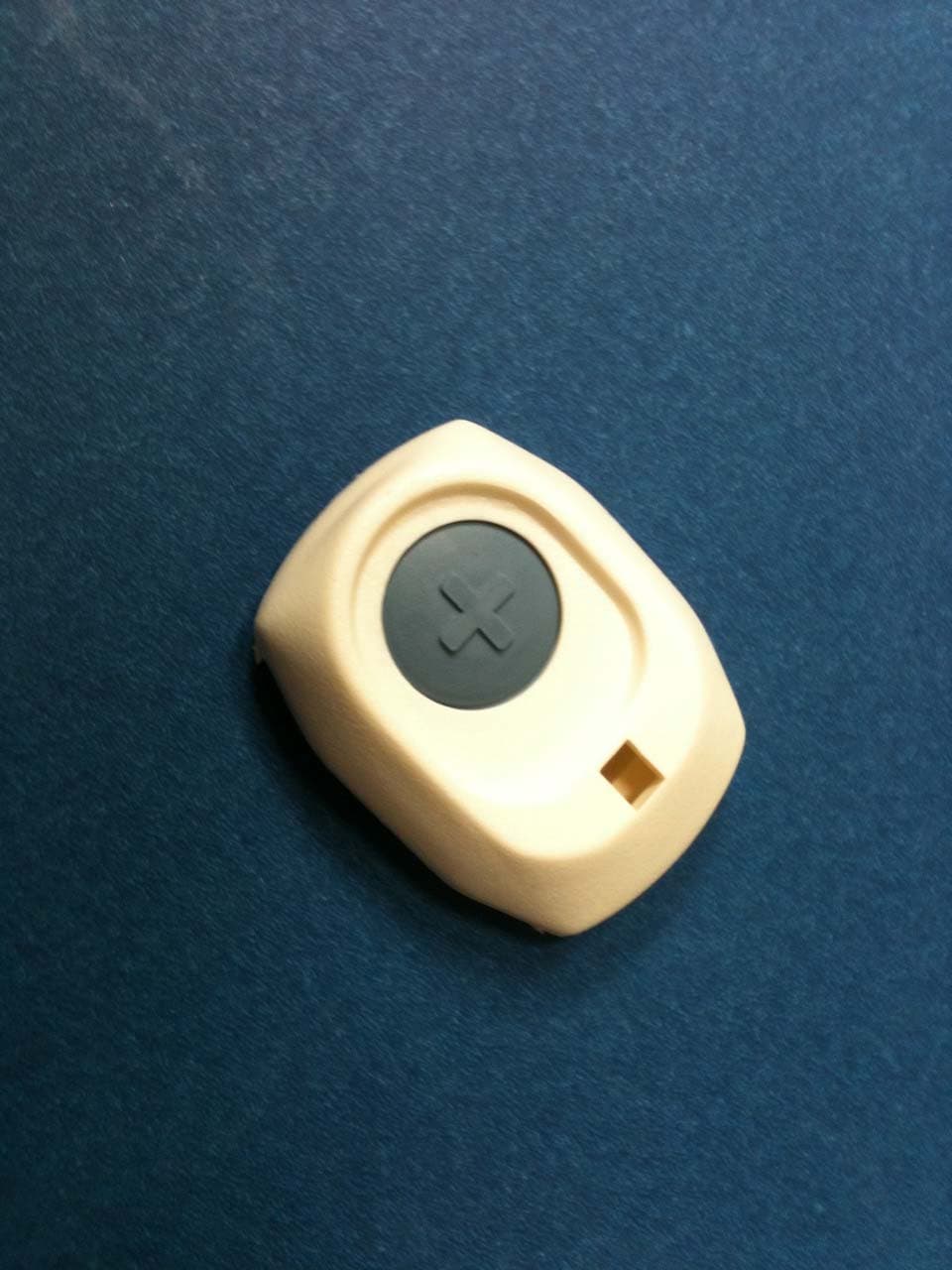
Click to zoom
Application Details
- Equipment Class
- DSC - Part 15 Security/Remote Control Transmitter
- Date of Grant
- Dec 21, 2010
- Application Purpose
- Original Equipment
- Date of Application
- Dec 21, 2010
- Equipment Note
- Remote pendant for healthcare system
- Frequency Range
- 418.00000000 - 418.00000000
- Company
- Mytrex Inc.
- Country
- United States
Documents & Files
Document Text
Text extracted from the exhibit documents filed with the FCC. Open a document above to read the original.
Users Manual
Mytrex MXD Users Manual Rev 1 December 14, 2010 1 Users Manual for the Mytrex Model MXD Personal Emergency Response System Manufactured by Mytrex, Inc. 10321 S. Beckstead Lane South Jordan, Utah 84095 (801)571-4121, fax (801)571-4606 Toll free (800)688-9576 fax (877)571-4606 www.rescuealert.com © 2010 All Rights Reserved Notes: Multiple listings may be requested for Rescue Alert and VRI. Also, the name “Mytrex Model MXD” may be replaced by “Mytrex RA 500” and VRI’s model may be named, “VRI 500.” Mytrex MXD Users Manual Rev 1 December 14, 2010 2 Introduction Congratulations! You have chosen the Mytrex MXD Personal Emergency Response System (PERS) system, which you have obtained through the following service provider: [Provider’s name Provider’s address Business Toll free number Response Center Toll Free Number (if different from business number) Fax Number Email address Web site] The MXD has been created to provide you comfort, reassurance, and peace of mind by making it possible for help to be just a touch of a button away. Pressing your waterproof PHB will immediately activate the MXD PERS unit. Within seconds, your response center will be notified of your need for assistance. When a call for help is received, the response center’s computers provide an attendant with all of your personal information. The attendant will talk to you through the MXD unit’s speakerphone. The attendant will then telephone your family, friends, or emergency services based on the type of assistance you need. Even if you cannot hear or speak to the attendant, help will be summoned for you. The MXD unit is fast and simple to install. Your service provider’s representative may connect the MXD unit during an installation visit, you may elect to do it yourself, or you may ask a friend or relative to install it for you. To ensure that you always receive the fastest response time possible, it is very important that you do the following: Notify your service provider of any changes that should be made to your personal account information. You can update your account by calling your service provider or by pressing your PHB and relaying the information to the attendant over the speakerphone. Your response center needs to be aware of changes to your address, telephone number, responder information, medical history, allergies, doctor information, hidden key location, and other information that you wish to have on file. Test your MXD unit at least once a month by pressing your PHB. Always wear your PHB! Mytrex MXD Users Manual Rev 1 December 14, 2010 3 This User’s Manual has been designed to help you make the most of your MXD PERS system. If you have any questions or concerns after reading this manual, please contact your service provider. MXD PERS Equipment Description OVERVIEW Your PERS system consists of the MXD base unit, telephone cord, and one or more Personal Help Buttons (PHBs) or other accessories. The MXD unit incorporates several important features, including: Compatible with Voice over IP (VoIP) telephone circuits in addition to standard telephone technology When enabled, interactive voice messages from the unit when the unit is calling the response center and during certain setup operations PHB detection ranges up to 600 feet from the base unit Simplified base unit buttons and indicator lights State of the art electronics Capacity to remember many PHB and other device codes Figure1. MXD Base Unit and Power Cord Base Unit Help Button STATUS Light Power Block and Cord (not removable from base unit) Mytrex MXD Users Manual Rev 1 December 14, 2010 4 Figure 2. Rear of MXD Base Unit Figure 3. Personal Help Button (PHB) Figure 4. MXD Telephone Cord Warning: Before your MXD system is ready for operation, it must be properly installed, have completed a range test, and completed its first call to the response center. See the detailed setup instructions later in this manual, or for additional information, contact your service provider. BASE UNIT CONTROLS AND INDICATOR The MXD base unit has three push buttons, including the large HELP button on the top of the base unit, and two small buttons on the back of the unit that are used during initial installation and at other times if needed. Each button is described below. WALL (large) Jack -- Insert large end of Rescue Alert telephone cord here PHONE (small) Jack -- Insert your handset’s telephone cord plug here RESET Button T/L (Test/Learn) Button Plug the large end into the “Wall” jack on the back of the base unit Plug the small end into the telephone jack on the wall Mytrex MXD Users Manual Rev 1 December 14, 2010 5 Base Unit Help Button (Figure 1) Normally, pushing the large blue Help Button on the front of your Rescue Alert base unit causes the unit to send a “Help needed” message to the response center. The Help Button also is used with the T/L button to conduct range tests and to program the MXD unit to recognize PHBs or other accessories. STATUS Light (Figure 1) A small STATUS light is located on the lower left edge of the unit’s large “Help” button. The STATUS light will display steady or flashing lights, in either red, green or orange color, depending on the status of the unit. See Page 15 for a more detailed description of the STATUS light signals and their meaning. T/L (Test/Learn) Button (Figure 2) The white T/L (Test/Learn) Button is located on the rear of your MXD unit. It is used to place your MXD unit into special operating modes to conduct PHB range tests, to program PHBs and other accessories, and to allow technical personnel to diagnose problems and adjust the unit. T/L Operating Modes Chart Voice Announcement (if enabled) If the T/L button is pushed: The base unit will be placed in the following mode: Tone Signal (if voice not enabled) The purpose of this mode is: “Range Test Mode” Once RANGE TEST One brief tone Test the range of the PHB and search for areas where the PHB signal is not detected by the base unit “Monitor Mode” Twice MONITOR…
Text truncated - open the document above for the full version.
ID Label/Location Info
Sample Drawing of label to be placed on the bottom of the RA3TX pendant: Dimensions approximately 0.75” x 0.48” F FCC ID: NY5RA3TX See Manual S/N:XXXXXX FCC ID: NY5RA3TX See Manual S/N:XXXXXX
Test Report
Client: Product Designation: RA3TX Report Number: 100146516ATL-005 All services undertaken are subject to the following general policy: This report is for the exclusive use of Intertek's Client and is provided pursuant to the agreement between Intertek and its Client. Intertek's responsibility and liability are limited to the terms and conditions of the agreement. Intertek assumes no liability to any party, other than to the Client in accordance with the agreement, for any loss, expense or damage occasioned by the use of this report. Only the Client is authorized to copy or distribute this report and then only in its entirety. Any use of the Intertek name or one of its marks for the sale or advertisement of the tested material, product or service must first be approved in writing by Intertek. The observations and test results in this report are relevant only to the sample tested. This report by itself does not imply that the material, product, or service is or has ever been under an Intertek certification program. This report must not be used to claim product endorsement by A2LA, NIST, or any agency of the US Government. Tested by: Tests performed by:Report reviewed by: Standard: Troy J. Ihle EMC Project Engineer Jeremy O. Pickens EMC Department Manager M ytrex, Inc. 10321 South Beckstead Lane South Jordan, UT 84095 Contact: Ernie Wessman Phone: 801.571.4121 Fax: 801.571.4606 TEST REPORT December 15, 2010 Intertek Testing Services NA Inc. 1950 Evergreen Blvd., Suite 100 Duluth, GA 30096 47 CFR Part 15, Subpart C (15.231 - Periodic operation in the band 40.66- 40.70 MHz and above 70 MHz) RSS-210, Issue 7, 2007 Page 1 of 21EMC Report for Mytrex, Inc. on the RA3TX 12/15/2010Report Number: 100146516ATL-005Issued: Intertek 2.0 Test Summary 1.0 Introduction and Conclusion Test DateTest Full NameResultSection System setup including cable interconnection details, support equipment and simplified block diagram. (System Setup)4.0 Overview of EUT (Low Power Transmitters) (EUT Overview)5.0 10/21/2010Restrictions (FCC 15C - 15.231(a))PASS6.0 10/21/2010Duty Cycle Determination (FCC 15A - 15.35(c))7.0 12/01/2010Radiated Emissions (FCC 15C - 15.231(b))PASS8.0 12/15/2010Bandwidth Requirements (FCC 15C - 15.231(c))PASS9.0 Conducted Emissions for Intentional Radiators (FCC 15C - 15.207) was waived due to the device does not connect to the AC mains. NA The tests indicated in section 2.0 were performed on the product constructed as described in section 3.0. The remaining test sections are the verbatum text from the actual data sheets used during the investigation. These test sections include the test name, the specified test Method, a list of the actual Test Equipment Used, documentation Photos, Results and raw Data. No additions, deviations, or exclusions have been made from the standard(s) unless specifically noted. Based on the results of our investigation, we have concluded the product tested complies with the requirements of the standard(s) indicated. The results obtained in this test report pertain only to the item(s) tested. Page 2 of 21EMC Report for Mytrex, Inc. on the RA3TX 12/15/2010Report Number: 100146516ATL-005Issued: Intertek 3.0 Description of Equipment Under Test Equipment Under Test Description Manufacturer Model Number Serial Number Pendant Transmitter Mytrex, Inc. RA3TX NA EUT receive date: 10/21/2010, 11/30/2010 EUT receive condition: Good Description of EUT provided by Client: The RA3Tx is a personal help button for use with the MDX Personal Emergency Response System. Description of EUT exercising: During testing, the button was constantly depressed which resulted in a continuous, modulated transmission. Page 3 of 21EMC Report for Mytrex, Inc. on the RA3TX 12/15/2010Report Number: 100146516ATL-005Issued: Intertek System setup including cable interconnection details, support equipment and simplified block diagram. (System Setup) 4.0 Method: Record the details of EUTcabling, document the support equipment, and show the interconnections in a block diagram. Data: EUT Setup Diagram Drawing: Page 4 of 21EMC Report for Mytrex, Inc. on the RA3TX 12/15/2010Report Number: 100146516ATL-005Issued: Intertek System setup including cable interconnection details, support equipment and simplified block diagram. (System Setup) 4.0 Description EUT Cabling Connection Length Shielding FerritesIDFromTo None Support Equipment DescriptionManufacturerModel NumberSerial Number None Page 5 of 21EMC Report for Mytrex, Inc. on the RA3TX 12/15/2010Report Number: 100146516ATL-005Issued: Intertek Overview of EUT (Low Power Transmitters) (EUT Overview)5.0 Method: Complete the overview spreadsheet. Related Submittal(s) Grants: This report is for use with an application for certification of a low power transmitter. One transmitter is included in the application. Mytrex, Inc. 10321 Becks tead Lan e So uth Jo rdan , UT 84095 Trade Name & Model No. RA3TX FCC Identifier NY5RA3TX Frequency Range (MHz) 418 A nten na Typ e (15.203) PCB Mytrex, Inc. 10321 Becks tead Lan e So uth Jo rdan , UT 84095 Additions, deviations and exclusions from standards None This report is for use with an application for certification of a low power transmitter. One transmitter is included in the application. Applicant Manufacturer name & address Related Submittals and Grants: Data: Page 6 of 21EMC Report for Mytrex, Inc. on the RA3TX 12/15/2010Report Number: 100146516ATL-005Issued: Intertek Restrictions (FCC 15C - 15.231(a))6.0 Method: 15.231(a) The provisions of this section are restricted to periodic operation within the band 40.66-40.70 MHz and above 70 MHz. Except as shown in paragraph (e) of this section, the intentional radiator is restricted to the transmission of a control signal such as those used with alarm systems, door openers, remote switches, etc. Continuous transmissions, voice, video and the radio control of toys are not permitted. Data is permitted to be sent with a control signal. The following conditions shall be met to comply wit…
Text truncated - open the document above for the full version.
Contact Information
Applicant
Richard M Bangerter(President)
Test Firm
Intertek Testing Services NA Inc.Charles Parker
Technical Specifications
| # | Rule Parts | Frequency Range | Power Output |
|---|---|---|---|
| 1 | 15.231 | 418 MHz - 418 MHz | - |
Other Applications from Mytrex Inc.

NY5MAA01
May 21, 2015Remote Pendant for healthcare system
Equipment Class
DSC - Part 15 Security/Remote Control Transmitter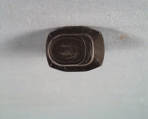
NY5RA3T
Aug 09, 1998Medical Emergency Transmitter
Equipment Class
DXX - Part 15 Low Power Communication Device Transmitter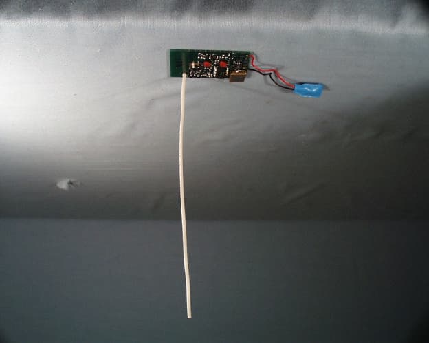
NY5RA3R
Aug 04, 1998Receiver for Medical Emergency Application
Equipment Class
CYY - Communications Receiver used w/Pt 15 Transmitter