NYC-GH58775.8GHz/2.4GHz 40 Channel Cordless Phone (Base)
Belco International Co Ltd
Click to zoom
Application Details
- Equipment Class
- DXX - Part 15 Low Power Communication Device Transmitter
- Date of Grant
- Sep 19, 2004
- Application Purpose
- Original Equipment
- Date of Application
- Sep 19, 2004
- Equipment Note
- 5.8GHz/2.4GHz 40 Channel Cordless Phone (Base)
- Frequency Range
- 5803.01900000 - 5816.01900000
- Company
- Belco International Co Ltd
- Country
- South Korea
Documents & Files
Document Text
Text extracted from the exhibit documents filed with the FCC. Open a document above to read the original.
Users Manual
- 4 - FCC WANTS YOU TO KNOW Warning : Changes or modifications to this unit expressly approved by the party responsible for compliance could void the user’s authority to operate the equipment. NOTE : This equipment has been tested and found to comply with the limits for a Class B digital device, pursuant to Part15 of the FCC Rules. These limits are designed to provided reasonable protection against harmful interference in a residential installation. This equipment generates, uses and can radiate radio frequency energy and, if not installed and used in accordance with the instructions, may cause harmful interference to radio communications. However, there is no guarantee that interference will not occur in a particular installation. If this equipment does cause harmful interference to radio or television reception, which can be determined by turning the equipment off and on, the user is encouraged to try to correct the interference by one or more of the following measures: ▪Reorient or relocate the receiving antenna. ▪Increase the separation between the equipment and receiver. ▪ Connect the equipment into an outlet on an outlet on a circuit different from that to which the receiver is connected. ▪ Consult the dealer or an experienced radio TV technician for help. NOTICE : If your home has specially wired alarm equipment connected to the telephone line, ensure the installation of this GH5877 does not disable your alarm equipment. If you have questions about what will disable alarm equipment, consult your telephone company or qualified installer. This device complies with Part15 of the FCC rules. Operation is subject to the following two conditions : (1) This device may not cause harmful interference, and (2) This device must accept any interference received, including interference that may cause undersired operation. Privacy of communications may not be ensured when using this phone.
Users Manual
- 1 - 5.8GHz Cordless Telephone BASIC MODEL: GH5877 - 2 - IMPORTANT SAFETY INSTRUCTIONS BEFORE USING YOUR TELEPHONE EQUIPMENT, BASIC SAFETY PRECAUTIONS SHOULD ALWAYS BE FOLLOWED TO REDUCE THE RISK OF FIRE, ELECTRIC SHOCK AND INJURY TO PERSONS, INCLUDING THE FOLLOWING: 1. Read and understand all instructions. 2. Follow all warnings and instructions marked on the product. 3. Unplug this product from the wall telephone jack and power outlet before cleaning. Do not use liquid cleaners or aerosol cleaners. Use a damp cloth for cleaning. 4. Do not use this product near water, for example, near a bath tub, wash bowl, kitchen sink, laundry tub, swimming pool, or in a wet basement. 5. Do not place this product on an unstable cart, stand or table. This product may fall, causing serious damage. 6. Slots or openings in the cabinet and the back and bottom are provided for ventilation, to protect it from overheating. These openings must not be blocked or covered. The openings should never be blocked by placing the product on a bed, or other similar surface. This product should never be placed near or over a radiator or heat register. 7. This product should be operated only from the type of power source indicated on the marking label. If you are not sure of the type of power supply to your home, consult your dealer or local power company. 8. Do not allow anything to rest on the power cord. Do not place this product where the cord will be damaged by persons stepping on it. 9. Do not overload wall outlets and extension cords, as this can result in fire or electric shock. 10. Never push objects of any kind into this product through cabinet slots, as they may touch dangerous voltage points or short out parts. This could result in fire or electric shock. Never spill liquid of any kind on the product. 11. To reduce the risk of electric shock, do not disassemble this product. Instead, when service or repair work is required, take it to a qualified technician. Opening or removing covers may expose you to dangerous voltages or other risks. Incorrect reassembly can cause electric shock when the appliance is subsequently used. 12. Unplug this product from the wall outlet and refer servicing to qualified service personnel under the following conditions: a. When the power supply cord or plug is damaged or frayed. b. If liquid has been spilled into the product. c. If the product has been exposed to rain or water. d. If the product does not operate normally, and proper operating instructions have been Followed, adjust only those controls that are covered by the operating instructions. Improper adjustment of other controls may result in damage and will often require extensive work by a qualified technician to restore the product to normal operation. e. If the product has been dropped or the cabinet has been damaged. f. If the product exhibits a distinct change in performance. 13. Avoid using a telephone (other than a cordless type) during an electrical storm. There may be a remote risk of electric shock from lightning. 14. Do not use the telephone to report a gas leak in the vicinity of the leak. 15. Use only the power cord and batteries indicated in this manual. Do not dispose of batteries in a fire. They may explode. Check with local codes for possible special disposal instructions. CAUTION Risk of explosion if battery is replaced by incorrect type. Replace only with the same or equivalent type recommended by the manufacturer. Dispose of used batteries according to the manufacturer’s instructions. - 3 - SAFETY INSTRUCTIONS FOR BATTERIES Safety Instructions for Batteries Handset Battery Pack CAUTION: Use only a southwestern Bell Freedom Phone approved battery pack in the handset of your GH5877 Cordless Telephone. To reduce the risk of fire or injury, always do the following when replacing, discarding or charging batteries. When handling the batteries, be careful not to short the battery with conducting materials such as rings, bracelets and keys. The battery or conducting materials may overheat and cause burns. Use only the following type and size of battery pack: FOR HANDSET UNIT: 3.6V 600mAh Nickel-Metal Hydride (Ni-MH) Battery, JB60AAANM3BMX, JB Energy (HK) Ltd. a. Do not dispose of the battery pack in a fire. The cell may explode. Check with local codes for possible special disposal instructions. b. Do not attempt to open or mutilate the battery pack. The chemicals are dangerous and may cause damage to the eyes or skin, and may be toxic if swallowed. c. Follow the charging instructions outlined in this manual. The EPA certified RBRC ® Battery Recycling Seal on the Nickel-Metal Hydride (Ni-MH) battery indicates that Southwestern Bell Freedom Phone Retail Sales is voluntarily participating in an industry program to collect and recycle these batteries at the end of their useful life, when taken out of service in the United States or Canada. The RBRC ® program provides a convenient alternative to placing used Ni-MH batteries into the trash or the municipal waste stream, which may be illegal in your areas. Please call 1-800-822-8837 for information on Ni-MH battery recycling and disposal bans/restrictions in your area. Southwestern Bell Freedom Phone Retail Sales’s involvement in this program is part of our commitment to preserving our environment and conserving our natural resources. RBRC ® is a trademark of the Rechargeable Battery Recycling Corporation. Save these Instructions - 4 - FCC WANTS YOU TO KNOW Warning : Changes or modifications to this unit expressly approved by the party responsible for compliance could void the user’s authority to operate the equipment. NOTE : This equipment has been tested and found to comply with the limits for a Class B digital device, pursuant to Part15 of the FCC Rules. These limits are designed to provided reasonable protection against harmful interference in a residential installation. This equipment generates, uses and can radiate radio frequency energy and, if not installed an…
Text truncated - open the document above for the full version.
Block Diagram
5877BLKB.sch-1 - Fri Jul 09 09:49:32 2004
External Photos
External photos FCC ID: NYC-GH5877 External photos FCC ID: NYC-GH5877
Internal Photos
Internal photos FCC ID: NYC-GH5877 Base assembly (View 1) Base assembly (View 2) Internal photos FCC ID: NYC-GH5877 Base Main PCB comp side Base Main PCB solder side (View 1) Internal photos FCC ID: NYC-GH5877 Base Main PCB solder side (View 2) Base Oscillator PCB comp side Internal photos FCC ID: NYC-GH5877 Base Oscillator PCB solder side
Operational Description
MODEL: GH5877 DESCRIPTION OF CIRCUIT OPERATION BASE UNIT : 1. BASE RF MODULE SEPARATED RX ANTENNA AND TX ANTENNA TO TRANSMIT THE RF SIGNAL. THE WIRING ANTENNA IS SOLDERED ON THE RF MODULE. 1) RX PART THE RECEIVER FRONT-END CONTAINS A BAND PASS FILTER, AND RF LOW NOISE AMPLIFIER, A ACTIVE TRANSISTOR MIXER, A CERAMIC FILTER AND 10.73MHz IF AMPLIFIER. ALSO IT INCLUDES BUFFER AMPLIFIERS FOR THE GENERATION OF LOCAL OSCILLATOR POWER. THIS FRONT-END RECEIVER RECEIVERS AND RF SIGNAL FROM THE ANTENNA. AND RF SIGNALS WITHIN THIS FREQUENCY RANGE IS 2468MHz ~ 2479.7MHz PASS THROUGH RF AMP (Q1) AND BAND PASS FITER. AFTER PASSING THROUGH THE BAND PASS FILTER AND THE SIGNAL IS MIXED WITHIN 1’ST LOCAL FREQUENCY FROM VOLTAGE CONTROLLED OSCILLATOR. THE SIGNAL IS AMPLIFIED ON THE OF AMP TRANSISTOR (Q3) AND THE SIGNAL PASS THROUGH THE CERAMIC FILTER (10.73MHz). AFTER THE IF SIGNAL PASS THE CERAMIC FILTER, THE SIGNAL ENTER BY THE FM IF(INTERMEDIATE FREQUENCY) IC1. AND THE SIGNAL IS MIXED IN THE FM IF IC (3361). THE SIGNAL PASS THROUGH THE LC FILTER. THE OUTPUT SIGNAL IN THE FM IF IC STREAMS FROM THE AF-OUT TERMINAL OF THE CONNECTOR TO THE BASE. FIG. 1 RX ANTENNA IC 1 AF-OUT BPF F1 LNA Q1 VCO MIXER 1’ST LOCAL FREQUENCY F2 10.73MHz IF IC 3361 GND LC FILTER 2’nd LOCAL FREQ. TCXO 11.15MHz 2)TX PART THE SIGNAL IS MADE TO THE BASE, ENTER BY THE AF-IN TERMINAL OF THE CONNECTOR(CON1 OF PIN NO.10). THE SIGNAL SEND THE MOD TERMINAL OF THE TX VCO. THE SIGNAL IS MIXED IN THE TX VCO MIXING THE RF SIGNAL, THE RF SIGNAL ADJUST THE TRIMMER CAPACITOR (VC1). THE RF SIGNAL ENTER BY THE TRANSMISSION POWER AMP TRANSISTOR Q7 THE SIGNAL IS AMPLITUDE IN THE Q5,Q10. ENTER BY THE BAND PASS FILTER. THE RF SIGNAL PASS THROUGH THE BAND PASS FILTER, TOWARDS THE ANT. THE LAST TRANSMISSION RF SIGNAL IS 5803.019MHz ~ 5816.019MHz. FIG. 2 The demodulated signal, resulting from Double Super Heterodyne system, which appears at output Pin no.3 of J 3 is sent to U2 (COMPANDER IC) Pin no.16 for Expansion. The expended audio signal output from Pin no.19 is coupled to Q1,Q3 during the TEL. mode The audio signal is sent to the Telephone Line via Q3. The demodulated data code from J3 Pin no.3 is Generated by U5-C, U5-B. It’s output is connected to CODE Input Pin no.14 of IC3. The Audio signal receiving from TEL-LINE is input to U2 Pin no.8 for compression. The compressed audio signal from Pin no.1 of U2 is connected to Pin no.10 of J3 for TX modulation. RF MODULE AF-IN VCO BPF4 5.8GHz TX ANTENNA PLL IC IC2 Q5,7,10 TCXO 11.15MHz TREMMER CAP. VC1 Pin no.31 of IC3 is the output port for data codes that should be transmitted to the handset the data code is connected to Pin no.10 of J3 for modulation. Line controlling is done by Pin no.18 of IC3. Ring signal monitored by U5-A is detected by Pin no.16 of IC3 resulting a data code to the handset. DTMF dialing is generated by IC3 Pin no.20~25 this signal output through the U5-D. When the handset is placed on the base cradle, the charging is detected by Pin no.13 of IC3 and IC3 sends data codes to handset for security code setting. When the handset is far away form base unit, squelch circuit of RF module operates and Pin no. 5 of IC3 goes “HI”. This will be detected by the micro processor and after 20 sec. go to Stand by mode. The power to the base unit is supplied by U3(5V REGULATOR IC). LED display control Pin no.9 of IC3.
Schematics
5_8 RFBN_BC.sch-1 - Fri Mar 26 15:30:17 2004
Test Report
• The test results reported in this report shall refer only to the sample actually tested and shall not refer or be deemed to refer to bulk from which such a sample may be said to have been obtained. • This report shall not be reproduced except in full without prior authorization form Intertek Testing Services Limited FCC ID: NYC-GH5877 Intertek Testing Services Hong Kong Ltd. 2/F., Garment Centre, 576 Castle Peak Road, Kowloon, Hong Kong. Tel: (852) 2173 8888 Fax: (852) 2741 1693 Website: www.hk.intertek-etlsemko.com Belco International Co., Ltd. Application For Certification 5.8GHz/2.4GHz 40 Channel Analog Modulation Cordless Phone – Base Unit (FCC ID: NYC-GH5877) 04064111 TL/Ann Choy August 4, 2004 INTERTEK TESTING SERVICES FCC ID: NYC-GH5877 i LIST OF EXHIBITS INTRODUCTION EXHIBIT 1: General Description EXHIBIT 2: System Test Configuration EXHIBIT 3: Emission Results EXHIBIT 4: Equipment Photographs EXHIBIT 5: Product Labelling EXHIBIT 6: Technical Specifications EXHIBIT 7: Instruction Manual EXHIBIT 8: Security Code Information INTERTEK TESTING SERVICES FCC ID: NYC-GH5877 ii MEASUREMENT/TECHNICAL REPORT Belco International Co., Ltd. - MODEL: GH-5877(XXXXX) FCC ID: NYC-GH5877 This report concerns (check one:) Original Grant X Class II Change Equipment Type : DXT Deferred grant requested per 47 CFR 0.457(d)(1)(ii)? Yes No X If yes, defer until : date Company Name agrees to notify the Commission by: date of the intended date of announcement of the product so that the grant can be issued on that date. Transition Rules Request per 15.37 ? Yes No X If no, assumed Part 15, Subpart C for intentional radiator - the new 47 CFR [12-08-03 Edition] Provision. Report prepared by: Tommy Leung Intertek Testing Services. 2/F., Garment Centre, 576 Castle Peak Road, Kowloon, Hong Kong. Phone : 852-2173-8538 Fax: 852-2741-1693 INTERTEK TESTING SERVICES FCC ID: NYC-GH5877 iii Table of Contents 1.0 General Description ............................................................................................2 1.1 Product Description..........................................................................................2 1.2 Related Submittal(s) Grants ............................................................................3 1.3 Test Methodology ............................................................................................3 1.4 Test Facility ......................................................................................................3 2.0 System Test Configuration ...................................................................................5 2.1 Justification.......................................................................................................5 2.2 EUT Exercising Software.................................................................................5 2.3 Support Equipment List and Description.........................................................6 2.4 Measurement Uncertainty ...............................................................................7 2.5 Equipment Modification ...................................................................................7 3.0 Emission Results ...................................................................................................9 3.1 Field Strength Calculation .............................................................................10 3.2 Radiated Emission Configuration Photograph - Base Unit ..........................11 3.3 Radiated Emission Data - Base Unit.............................................................12 3.4 Radiated Emission on the bandedge ............................................................16 3.5 Line Conducted Configuration Photograph - Base Unit ...............................18 3.6 Line Conducted Emission Data - Base Unit..................................................19 4.0 Equipment Photographs .....................................................................................22 5.0 Product Labelling .................................................................................................24 6.0 Technical Specifications .....................................................................................26 7.0 Instruction Manual ...............................................................................................28 8.0 Security Code Information ..................................................................................30 INTERTEK TESTING SERVICES FCC ID: NYC-GH5877 iv List of attached file Exhibit type File Description filename Test Report Test Report report.pdf Operation Description Technical Description descri.pdf Test Setup Photo Radiated Emission for Base config photos.doc Test Setup Photo Conducted Emission config photos.doc Test Report Conducted Emission Test Result conduct.pdf External Photo External Photo external photos.doc Internal Photo Internal Photo internal photos.doc Block Diagram Block Diagram block.pdf Schematics Circuit Diagram circuit.pdf ID Label/Location Label Artwork and Location label.pdf User Manual User Manual manual.pdf User Manual FCC Information fcc information.pdf INTERTEK TESTING SERVICES FCC ID: NYC-GH5877 1 EXHIBIT 1 GENERAL DESCRIPTION INTERTEK TESTING SERVICES FCC ID: NYC-GH5877 2 1.0 General Description 1.1 Product Description The GH-5877 is a 5.8GHz/2.4GHz 40 Channel Analog Modulation Cordless Phone. The unit is capable of either tone or pulse dialing. The internal power supply's isolation is accomplished through a power transformer having an adequate dielectric rating. The circuit wiring is consistent under the requirement of part 68. The handset unit consists of a keypad with twelve standard keys (0,...9,*,#), four function keys (Mem, Flash, Redial, Mute), and one channel switch key. A Talk key is provided to control pick/release telephone line in a toggle base. The base unit has a page key, which is used to page the handset unit. The antennas used in base unit and handset are integral, and the…
Text truncated - open the document above for the full version.
Test Report
Report No.:04064111 Talk Mode Ctrl No.:N/A PAGE 1 Tested By:Hong, Report No.:04064111 Scan Settings (1 Range) |--------- Frequencies -----------||----------- Receiver Settings ------------| Start Stop Step IF BW Detector M-Time Atten Preamp OpRge 150k 30M 5k 10k PK+AV 10ms AUTO LN OFF 60dB Final Measurement: x QP / + AV Meas Time: 1 s Subranges: 16 Acc Margin: 20dB Transducer No. Start Stop Name 21 9k 30M EW0698 0 10 20 30 40 50 60 70 80 90 dBuV 100 0.15 MHz 30 110 F15Q F15A Report No.:04064111 Talk Mode Ctrl No.:N/A Tested By:Hong, Report No.:04064111 Scan Settings (1 Range) |--------- Frequencies -----------||----------- Receiver Settings ------------| Start Stop Step IF BW Detector M-Time Atten Preamp OpRge 150k 30M 5k 10k PK+AV 10ms AUTO LN OFF 60dB Final Measurement Results: no Results
Test Setup Photos
The Worst Case Configuration Photographs FCC ID: NYC-GH5877 Radiated Emission – Base Front View Rear View The Worst Case Configuration Photographs FCC ID: NYC-GH5877 Conducted Emission Front View Rear View The Worst Case Configuration Photographs FCC ID: NYC-GH5877 Conducted Emission Side View
Contact Information
Applicant
Diana Jung(Certification Management)
Technical Contact
Intertek Testing Services Hong Kong Ltd.Tommy Leung
[email protected]852-2173-8538
2/F., Garment Centre, · Kowloon · Hong Kong
Non-Technical Contact
Intertek Testing Services Hong Kong Ltd.Tommy Leung
[email protected]852-2173-8538
Test Firm
Intertek Testing Services Hong KongBilly Chow
Technical Specifications
| # | Rule Parts | Frequency Range | Power Output |
|---|---|---|---|
| 1 | 15C | 5.80 GHz - 5.82 GHz | - |
Other Applications from Belco International Co Ltd

NYC-PM2400
Mar 31, 20052.4 GHz Analog Cordless Telephone
Equipment Class
DXT - Part 15 Low Power Transceiver, Rx Verified
NYC-PM2420
Mar 28, 20052.4 GHz Analog Cordless Telephone
Equipment Class
DXT - Part 15 Low Power Transceiver, Rx Verified
NYC-PM5820H
Dec 13, 20045.8GHz/2.4GHz 40 Channel Cordless Phone (Handset)
Equipment Class
DXX - Part 15 Low Power Communication Device Transmitter
NYC-PM5820
Dec 13, 20045.8GHz/2.4GHz 40 Channel Cordless Phone (Base)
Equipment Class
DXX - Part 15 Low Power Communication Device Transmitter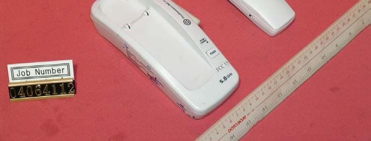
NYC-GH5877H
Sep 19, 20045.8GHz/2.4GHz 40 Channel Cordless Phone (Handset)
Equipment Class
DXX - Part 15 Low Power Communication Device Transmitter