NYC-PM58205.8GHz/2.4GHz 40 Channel Cordless Phone (Base)
Belco International Co Ltd
Click to zoom
Application Details
- Equipment Class
- DXX - Part 15 Low Power Communication Device Transmitter
- Date of Grant
- Dec 13, 2004
- Application Purpose
- Original Equipment
- Date of Application
- Dec 13, 2004
- Equipment Note
- 5.8GHz/2.4GHz 40 Channel Cordless Phone (Base)
- Frequency Range
- 5803.01900000 - 5816.01900000
- Company
- Belco International Co Ltd
- Country
- South Korea
Documents & Files
Document Text
Text extracted from the exhibit documents filed with the FCC. Open a document above to read the original.
Users Manual
www.phonemate.com INSTALLATION AND OPERATING GUIDE Model PM5820 5.8GHz CORDLESS TELEPHONE WITH CALL WAITING CALLER ID PM5820Manual_En-ˆ • ́ 2004.10.6 12:59 PM ̆ ` 1 AGFA SelectSet Avantra 25 PhoneMate and the PhoneMate Logo are registered trademarks of PhoneMate Corporation and are used under license from PhoneMate Corporation. Thank you for purchasing this PhoneMate Telephone. Please read this manual carefully prior to using. IMPORTANT SAFETY INSTRUCTIONS ........................................................................1 FCC REGULATIONS ...................................................................................................3 IC REGULATIONS ......................................................................................................5 BATTERY CAUTIONARY INSTRUCTIONS ....................................................................6 PM5820 PARTS CHECKLIST .......................................................................................7 CONTROLS AND FEATURES ......................................................................................8 CHOOSING A LOCATION .......................................................................................12 TELEPHONE SET-UP.................................................................................................13 BATTERY INSTALLATION .........................................................................................15 HEADSET AND BELT CLIP ........................................................................................16 BASIC OPERATION ..................................................................................................17 SETTINGS................................................................................................................18 SPEED DIALING .......................................................................................................24 CALLER ID ...............................................................................................................29 OTHER FEATURES ....................................................................................................33 CARE AND MAINTENANCE .....................................................................................34 TROUBLE SHOOTING..............................................................................................35 GLOSSARY...............................................................................................................37 WARRANTY STATEMENT .........................................................................................38 PM5820 TABLE OF CONTENTS PM5820Manual_En-ˆ • ́ 2004.10.6 12:59 PM ̆ ` 3 AGFA SelectSet Avantra 25 40 NOTES 1 !! Always follow basic safety precautions when using this product to reduce the risk of injury, fire, or electrical shock. When using this product, basic precautions should always be followed to reduce the risk of fire, electric shock and injury to persons, including the following: 1.Read and understand all instructions 2.Follow all warnings and instructions marked on the product. 3.Use only with class 2 power source DC 9V 300mA. 4.Unplug this product from the wall outlet before cleaning. Do not use liquid cleaners or aerosol cleaners. Use a damp cloth for cleaning. 5.Do not use this product near water; for example, near a bathtub, wash bowl, kitchen sink, or laundry tub, in a wet basement or near a swimming pool. 6.Do not place this product on an unstable cart, stand, or table. The product may fall causing serious damage to the product. 7.Slots and openings in the cabinet back or bottom are provided for ventilation. To protect it from overheating, these openings must not be blocked or covered. The openings should never be blocked by placing the product on the bed, sofa, rug, or other similar surface. This product should never be placed near or over a radiator or heat register. This product should not be placed in an enclosed environment unless proper ventilation is provided. 8.Do not allow anything to rest on the power cord. Do not locate this product where the cord will be abused by animals or persons walking on it. 9.Do not overload wall outlets and extension cords as this can result in risk of fire or electrical shock. 10.Never push objects of any kind into this product through cabinets slots as they may touch dangerous voltage points or short out parts that could result in a risk of fire or electrical shock. Never spill liquid of any kind on the product. 11.To reduce the risk of electrical shock, do not disassemble this product. Instead take it to a qualified service person when service or repair work is required. Opening or removing covers may expose you to dangerous voltages or other risks. Incorrect re- assembly can cause electrical shock when the appliance is subsequently used. 12.Unplug all cords and refer servicing to qualified service personnel under the following conditions: iWhen the power supply cord or plug is damaged or frayed iiIf liquid has been spilled into the product. iiiIf the product has been exposed to rain or water. ivIf the product does not operate normally by following the operating instructions, adjust only those controls covered in the operating instructions. Improper Model PM5820 IMPORTANT SAFETY INSTRUCTIONS !! PM5820Manual_En-ˆ • ́ 2004.10.6 12:59 PM ̆ ` 5 AGFA SelectSet Avantra 25 2 adjustment of other controls may result in damage and require work by a qualified technician to restore the product to normal operation. 13.Avoid using a telephone (other than a cordless type) during an electrical storm. There maybe a remote risk of electric shock from lightning. 14.Do not use a telephone to report a gas leak in the vicinity of the leak. IF YOUR PRODUCT UTILIZES BATTERIES, THE FOLLOWING ADDITIONAL PRECAUTIONS SHOULD BE OBSERVED: 1.Use only the type and size of batteries specified in the users manual. 2.Do not dispose of batteries in a fire. The cells may explode. Check with local codes for possible …
Text truncated - open the document above for the full version.
Users Manual
38 This limited warranty gives you specific legal rights: you may also have other rights, which vary from state to state. The limited warranty is extended only to the original consumer of a PhoneMate branded product by the Manufacturer and is valid only with respect to consumers within the United States of America and Canada. Should this product prove defective by reason of improper workmanship or material during the period of one (1) year from date of original purchase, the Manufacturer will repair or, at its option, replace the product without charge for parts or labor. If Manufacturer elects to replace the product, such replacement may be accomplished with a factory- reconditioned unit. This limited warranty does not apply: (a) to any product damaged by accident, misuse, improper line voltage, lightning, fire, water, or other acts of nature, (b) if the product is altered or repaired by anyone other than the Manufacturer or one of its authorized warranty stations or (c) if the FCC-approved connector plugs are removed. This limited warranty does not cover broken or marred cabinets. Except to the extent prohibited by law, all implied warranties made by the Manufacturer in connection with this product are limited in duration to a period of one (1) year from the date of original purchase, and no warranties, whether expressed or implied, shall apply to this product after said period. Should this product prove defective in workmanship or material, the consumer’s sole remedies shall be such repair or replacement as is herein above provided. Under no circumstances shall the Manufacturer or PhoneMate Corporation be liable for any loss or damage, direct, consequential, or incidental arising out of the use of or inability to use this product. Some states do not allow limitations on how long an implied warranty lasts or the exclusion or limitation of incidental or consequential damages, so the above limitations or exclusions may not apply to you. In order to obtain warranty service, you must provide evidence of purchase date. For your convenience, keep the dealer’s dated bill of sales or delivery ticket as evidence of the purchase date. PhoneMate and the PhoneMate Logo are registered trademarks of PhoneMate Corporation and are used under license from PhoneMate Corporation. WARRANTY IMPORTANT! SALES SLIP OR EVIDENCE OF PURCHASE DATE REQUIRED. 3 1.This equipment complies with Part 68 of the FCC rules and the requirements adopted by the ACTA. On the bottomof this equipment is a label that contains, among other information, a product identifier in the format US : AAAEQ##TXXXX. If requested, this number must be provided to the telephone company. 2.The USOC number of the registration jack for the equipment is RJ11C. 3.A FCC compliant telephone cord and modular plug is provided with this equipment. This equipment is designed to be connected to the telephone network or premises wiring using a compatible modular jack which is Part 68 compliant. See Installation Instructions for details. 4.The REN is used to determine the quantity of devices which may be connected to the telephone line. Excessive RENs on the telephone line may result in the devices not ringing in response to an incoming call. In most, but not all areas, the sum of RENs should not exceed five (5.0). To be certain of the number of devices that may be connected to a line, as determined by the total RENs, contact the local telephone company. 5.If this terminal equipment causes harm to the telephone network, the telephone company will notify you in advance that temporary discontinuance of service may be required. But if advance notice isn’t practical, the telephone company will notify the customer as soon as possible. Also, you will be advised of your right to file a complaint with the FCC if you believe it is unnecessary. 6.The telephone company may make changes in its facilities, equipment, operations or procedures that could affect the operation of the equipment. If this happens the telephone company will provide advance notice in order for you to make necessary modifications to maintain uninterrupted services. 7.The equipment cannot be used on public coin phone service provided by the telephone company. Connection to party line service is subject to state tariffs. 8. Please follow all instructions when replacing any parts (e.g. battery replacement section), otherwise do not attempt to alternate or repair any parts of the device except those specified. 9.This equipment, if it uses a telephone handset is hearing aid compatible. 10. If trouble is experienced with this equipment, for repair or warranty information, please contact the service center below. If the equipment is causing harm to the telephone network, the telephone company may request that you disconnect the equipment until the problem is resolved. FCC REGULATIONS Model PM5820 WARNING:Changes or modifications to this unit not expressly approved by the party responsible for compliance could void the user 's authority to operate the equipment. PM5820Manual_En-ˆ• ́ 2004.10.6 12:59 PM ̆` 9 AGFA SelectSet Avantra 25 4 Service can be obtained at: PhoneMate Service C enter 14515 Valley View Ave. # B Santa Fe Springs, C A 90670 TEL : 1-562-407-0227 I N T E R FE R E N C E I N FO R MA T I O N : P A R T 1 5 O F FC C R U L E S Some telephone equipment generates and uses radio frequency energy, which if not properly installed, may cause interference to radio and television reception. This unit has been tested and found to comply with the limits for a C lass B computing device in accordance with the specifications in Part 15 of the FC C rules. These specifications are designed to provide reasonable protection against such interference in a residential installation. If this equipment does cause interference to radio or television reception, when itÕs in use, the user is encourage to try to correct the interference by one or more of the following measures: A.Where it can be done safely, reorient the…
Text truncated - open the document above for the full version.
Block Diagram
5820BLKB.sch-1 - Thu Oct 14 17:41:14 2004
External Photos
External photos FCC ID: NYC-PM5820 External photos FCC ID: NYC-PM5820
Internal Photos
Internal photos FCC ID: NYC-PM5820 Base assembly Base Main PCB comp side (View 1) Internal photos FCC ID: NYC-PM5820 Base Main PCB comp side (View 2) Base Main PCB solder side Internal photos FCC ID: NYC-PM5820 Base Page Key front side Base Page Key rear side Internal photos FCC ID: NYC-PM5820 Base Oscillator PCB comp side Base Oscillator PCB solder side
Operational Description
MODEL: PM5820 DESCRIPTION OF CIRCUIT OPERATION BASE UNIT : 1. BASE RF MODULE SEPARATED RX ANTENNA AND TX ANTENNA TO TRANSMIT THE RF SIGNAL. THE WIRING ANTENNA IS SOLDERED ON THE RF MODULE. 1) RX PART THE RECEIVER FRONT-END CONTAINS A BAND PASS FILTER, AND RF LOW NOISE AMPLIFIER, A ACTIVE TRANSISTOR MIXER, A CERAMIC FILTER AND 10.73MHz IF AMPLIFIER. ALSO IT INCLUDES BUFFER AMPLIFIERS FOR THE GENERATION OF LOCAL OSCILLATOR POWER. THIS FRONT-END RECEIVER RECEIVERS AND RF SIGNAL FROM THE ANTENNA. AND RF SIGNALS WITHIN THIS FREQUENCY RANGE IS 2468MHz ~ 2479.7MHz PASS THROUGH RF AMP (Q1) AND BAND PASS FITER. AFTER PASSING THROUGH THE BAND PASS FILTER AND THE SIGNAL IS MIXED WITHIN 1’ST LOCAL FREQUENCY FROM VOLTAGE CONTROLLED OSCILLATOR. THE SIGNAL IS AMPLIFIED ON THE OF AMP TRANSISTOR (Q3) AND THE SIGNAL PASS THROUGH THE CERAMIC FILTER (10.73MHz). AFTER THE IF SIGNAL PASS THE CERAMIC FILTER, THE SIGNAL ENTER BY THE FM IF(INTERMEDIATE FREQUENCY) IC1. AND THE SIGNAL IS MIXED IN THE FM IF IC (3361). THE SIGNAL PASS THROUGH THE LC FILTER. THE OUTPUT SIGNAL IN THE FM IF IC STREAMS FROM THE AF-OUT TERMINAL OF THE CONNECTOR TO THE BASE. FIG. 1 RX ANTENNA IC 1 AF-OUT BPF F1 LNA Q1 VCO MIXER 1’ST LOCAL FREQUENCY F3 10.73MHz IF IC 3361/DBL5018 GND LC FILTER 2’nd LOCAL FREQ. TCXO 11.15MHz 2)TX PART THE SIGNAL (AUDIO OR DATA SIGNAL) IS MADE TO THE BASE, ENTER BY THE AF-IN TERMINAL OF THE CONNECTOR (CON1 OF PIN NO.10). CARRIER SINGAL(TX FREQUENCY) IS GENARATED BY THE OSCILLATOR (Q8, C69,C68,C67,C65 AND VD2) CONTROLLED BY PLL IC. TX OSCILLATOR FREQUENCY IS FROM 1160.6038MHz TO 1163.2038MHz. AUDIO AND DATA SIGNAL SEND OUT BY MOULATE IT ON THE CARRIER SIGNAL THROUGH CHANGE THE CAPACITANCE OF VD2. TX FREQUENCY IS FROM 5803.019MHz TO 5816.019MHz. THE SIGNAL IS MIXED IN THE TX VCO MIXING THE RF SIGNAL, THE RF SIGNAL ADJUST THE TRIMMER CAPACITOR (VC1). THE RF SIGNAL ENTER BY THE TRANSMISSION POWER AMP TRANSISTOR Q7 THE SIGNAL IS AMPLITUDE IN THE Q5,Q10. ENTER BY THE BAND PASS FILTER. THE RF SIGNAL PASS THROUGH THE BAND PASS FILTER, TOWARDS THE ANT. THE LAST TRANSMISSION RF SIGNAL IS 5803.019MHz ~ 5816.019MHz. (VD2, R36) FIG. 2 The demodulated signal, resulting from Double Super Heterodyne system, which appears at output Pin no.3 of J 3 is sent to IC2 (COMPANDER IC) Pin no.16 for Expansion. The expended audio signal output from Pin no.19 is coupled to Q8,Q3 during the TEL. mode The audio signal is sent to the Telephone Line via Q3. The demodulated data code from J3 Pin no.3 is generated by U5-C, U5-B. RF MODULE AF-IN VCO BPF4 5.8GHz TX ANTENNA PLL IC IC2 Q5,7,10 TCXO 11.15MHz TREMMER CAP. VC1 It’s output is connected to CODE Input Pin no.31 of IC4. The Audio signal receiving from TEL-LINE is input to IC2 Pin no.8 for compression. The compressed audio signal from Pin no.1 of IC2 is connected to Pin no.10 of J3 for TX modulation. Pin no.21 of IC4 is the output port for data codes that should be transmitted to the handset the data code is connected to Pin no.10 of J3 for modulation. Line controlling is done by Pin no.10 of IC4. Ring signal monitored by U5-A is detected by Pin no.9 of IC4 resulting a data code to the handset. DTMF dialing is generated by IC4 Pin no.38 this signal output through the Q8. When the handset is placed on the base cradle, the charging is detected by Pin no.8 of IC4 and IC4 sends data codes to handset for security code setting. When the handset is far away from base unit, squelch circuit of RF module operates and Pin no.30 of IC4 goes “HI”. This will be detected by the micro processor and after 20 sec. the base unit go to stand by mode. The power to the base unit is supplied by IC5(5V REGULATOR IC). LED display control Pin no.23 of IC4. HANDSET : 1. PORTABLE RF MODULE SEPARATED RX ANTENNA AND TX ANTENNA TO TRANSMIT THE RF SIGNAL. THE WIRING ANTENNA IS SOLDERED ON THE RF MODULE. 1) RX RART THE RECEIVER FRONT-END CONTAINS A BAND PASS FILTER, AND RF LOW NOISE AMPLIFIER, ACTIVE TRANSISTOR MIXER, CERAMIC FILTER AND 10.73MHz “IF” AMPLIFTER. ALSO IT INCLUDES BUFFER AMPLIFIERS OR THE GENERATION OF LOCAL OSCILLATOR POWER. THIS FRONT-END RECEIVERS AND RF SIGNAL FROM THE ANTENNA. AND RF SIGNALS WITHIN THIS FREQUENCY RANGE IS 5803.019MHz ~ 516.019MHz PASS THROUGH RF AMP (Q1) AND BAND PASS FILTER.. AFTER PASSING THROUGH THE BAND PASS FILTER, THE SIGNAL IS MIXED WITHIN 1’ST LOCAL FREQUENCY FROM VOLTAGE CONTROLLED OSCILLATOR. THE SIGNAL IS AMPLIFIED ON THE IF AMP TRANSISTOR (Q3) AND THE SIGNAL PASS THROUGH THE CERANIC FILTER (10.73MHz) AFTER THE IF SIGNAL PASS THE MCF FILTER, THE SIGNAL ENTER BY THE FM IF (INTERMEDIATE FREQUENCY) IC. AND THE SIGNAL IS MIXED IN THE FM IF IC (3361). THE SIGNAL PASS THROUGH THE LC FILTER. THE OUTPUT SIGNAL IN THE FM IF IC STREAMS FROM THE AF-OUT TERMINAL OF THE CONNECTOR 1 TO THE PORTABLE. FIG.3 RX ANTENNA IF IC 3361/DBL5018 F4 10. 73MHz IC 2 AF-OUT BPF F1 LNA Q1,Q10VCO MIXER 1’ST LOCAL FREQUENCY LC FILTER2’nd LOCAL FREQ. TCXO 11.15MHz 2) TX PART THE SIGNAL(AUDIO OR DATA SIGNAL) IS MADE TO THE PORTABLE, ENTER BY THE AF-IN TERMINAL OF THE CONNECTOR. CARRIER SINGAL(TX FREQUENCY) IS GENARATED BY THE OSCILLATOR (Q8,C69,C68,C67,C65 AND VD2) CONTROLLED BY PLL IC. TX OSCILLATOR FREQUENCY IS FROM 822.667MHz TO 826.567MHz. AUDIO & DATA SIGNAL SEND OUT BY MOULATE IT ON THE CARRIER SIGNAL THROUGH CHANGE THE CAPACITANCE OF VD2. TX FREQUENCY IS FROM 2468MHz TO 2479.7MHz. THE SIGNAL IS MIXED IN THE TX VCO MIXING THE RF SIGNAL, THE RF SIGNAL ADJUST THE TRIMMER CAPACITOR VC1. THE RF SIGNAL ENTER BY THE TRANSMISSION POWER AMP TRANSISTOR (Q5,7). ENTER BY THE BAND PASS FILTER. THE RF SIGNAL PASS THROUGH THE BAND PASS FILTER, TO WARDS THE ANT. THE LAST TRANSMISSION RF SIGNAL IS 2468MHz ~ 2479.7MHz. (VD2, R36) FIG. 4 The demodulated signal, resulting from Double Super Heterodyne system, which appears at output Pin no.3 of CON1 is connected to U2 Pin no.16 Expander input. The audio output RF MODULE AF-IN VCO TCXO 11.15MHz TREMMER CAP. VC1 Q5,7 F3 2475MHz TX ANTHNNA PLL IC IC1 from U2 Pin no.19 is f…
Text truncated - open the document above for the full version.
Schematics
5820b.sch-1 - Tue Oct 12 13:55:07 2004 5_8 RFBN_BC.sch-1 - Fri Mar 26 15:30:17 2004
Test Report
• The test results reported in this report shall refer only to the sample actually tested and shall not refer or be deemed to refer to bulk from which such a sample may be said to have been obtained. • This report shall not be reproduced except in full without prior authorization form Intertek Testing Services Limited FCC ID: NYC-PM5820 Intertek Testing Services Hong Kong Ltd. 2/F., Garment Centre, 576 Castle Peak Road, Kowloon, Hong Kong. Tel: (852) 2173 8888 Fax: (852) 2741 1693 Website: www.hk.intertek-etlsemko.com Belco International Co., Ltd. Application For Certification 5.8GHz/2.4GHz 40 Channel Analog Modulation Cordless Phone with Caller ID - Base Unit (FCC ID: NYC-PM5820) 04171251 TL/Ann Choy October 11, 2004 INTERTEK TESTING SERVICES FCC ID: NYC-PM5820 i LIST OF EXHIBITS INTRODUCTION EXHIBIT 1: General Description EXHIBIT 2: System Test Configuration EXHIBIT 3: Emission Results EXHIBIT 4: Equipment Photographs EXHIBIT 5: Product Labelling EXHIBIT 6: Technical Specifications EXHIBIT 7: Instruction Manual EXHIBIT 8: Security Code Information INTERTEK TESTING SERVICES FCC ID: NYC-PM5820 ii MEASUREMENT/TECHNICAL REPORT Belco International Co., Ltd. - MODEL: PM5820(XXXXX) FCC ID: NYC-PM5820 This report concerns (check one:) Original Grant X Class II Change Equipment Type : DXT - Cordless Telephone Deferred grant requested per 47 CFR 0.457(d)(1)(ii)? Yes No X If yes, defer until : date Company Name agrees to notify the Commission by: date of the intended date of announcement of the product so that the grant can be issued on that date. Transition Rules Request per 15.37 ? Yes No X If no, assumed Part 15, Subpart C for intentional radiator - the new 47 CFR [12-08-03 Edition] Provision. Report prepared by: Tommy Leung Intertek Testing Services. 2/F., Garment Centre, 576 Castle Peak Road, Kowloon, Hong Kong. Phone : 852-2173-8538 Fax: 852-2741-1693 INTERTEK TESTING SERVICES FCC ID: NYC-PM5820 iii Table of Contents 1.0 General Description ............................................................................................2 1.1 Product Description ............................................................................................2 1.2 Related Submittal(s) Grants ...............................................................................3 1.3 Test Methodology ...............................................................................................3 1.4 Test Facility .........................................................................................................3 2.0 System Test Configuration ...................................................................................5 2.1 Justification .........................................................................................................5 2.2 EUT Exercising Software....................................................................................5 2.3 Support Equipment List and Description ...........................................................6 2.4 Measurement Uncertainty ..................................................................................7 2.5 Equipment Modification ......................................................................................7 3.0 Emission Results ...................................................................................................9 3.1 Field Strength Calculation................................................................................10 3.2 Radiated Emission Configuration Photograph - Base Unit.............................11 3.3 Radiated Emission Data - Base Unit ...............................................................12 3.4 Radiated Emission on the bandedge ...............................................................16 3.5 Line Conducted Configuration Photograph - Base Unit ..................................18 3.6 Line Conducted Emission Data - Base Unit ....................................................19 4.0 Equipment Photographs .....................................................................................22 5.0 Product Labelling .................................................................................................24 6.0 Technical Specifications .....................................................................................26 7.0 Instruction Manual ...............................................................................................28 8.0 Security Code Information ..................................................................................30 INTERTEK TESTING SERVICES FCC ID: NYC-PM5820 iv List of attached file Exhibit type File Description filename Test Report Test Report report.pdf Operation Description Technical Description descri.pdf Test Setup Photo Radiated Emission for Base config photos.doc Test Report Emission Plot emission.pdf Test Setup Photo Conducted Emission config photos.doc Test Report Conducted Emission Test Result conduct.pdf External Photo External Photo external photos.doc Internal Photo Internal Photo internal photos.doc Block Diagram Block Diagram block.pdf Schematics Circuit Diagram circuit.pdf ID Label/Location Label Artwork and Location label.pdf User Manual User Manual manual.pdf User Manual FCC Information fcc information.pdf INTERTEK TESTING SERVICES FCC ID: NYC-PM5820 1 EXHIBIT 1 GENERAL DESCRIPTION INTERTEK TESTING SERVICES FCC ID: NYC-PM5820 2 1.0 General Description 1.1 Product Description The PM5820 is a 5.8GHz/2.4GHz 40 Channel Analog Modulation Cordless Phone with Caller ID. Base Unit and handset operate at frequency of 5803.019MHz to 5816.019MHz and 2468.000MHz to 2479.700MHz respectively. The unit is capable of either tone or pulse dialing. The internal power supply's isolation is accomplished through a power transformer having an adequate dielectric rating. The circuit wiring is consistent under the requirement of part 68. The handset unit consists of a keypad with twelve standard keys (0,...9,*,#), six function keys (CID, Mem/Save, Del/…
Text truncated - open the document above for the full version.
Test Report
Report No.:04171251 Talk Mode Ctrl No.:N/A PAGE 1 Tested By:Hong, Report No.:04171251 Scan Settings (1 Range) |--------- Frequencies -----------||----------- Receiver Settings ------------| Start Stop Step IF BW Detector M-Time Atten Preamp OpRge 150k 30M 5k 10k PK+AV 10ms AUTO LN OFF 60dB Final Measurement: x QP / + AV Meas Time: 1 s Subranges: 16 Acc Margin: 20dB Transducer No. Start Stop Name 21 9k 30M EW0698 0 10 20 30 40 50 60 70 80 90 dBuV 100 0.15 MHz 30 110 F15Q F15A Report No.:04171251 Talk Mode Ctrl No.:N/A Tested By:Hong, Report No.:04171251 Scan Settings (1 Range) |--------- Frequencies -----------||----------- Receiver Settings ------------| Start Stop Step IF BW Detector M-Time Atten Preamp OpRge 150k 30M 5k 10k PK+AV 10ms AUTO LN OFF 60dB Final Measurement Results: no Results
Test Setup Photos
The Worst Case Configuration Photographs FCC ID: NYC-PM5820 Radiated Emission – Base Front View Rear View The Worst Case Configuration Photographs FCC ID: NYC-PM5820 Conducted Emission Front View Rear View The Worst Case Configuration Photographs FCC ID: NYC-PM5820 Conducted Emission Side View
Contact Information
Applicant
Diana Jung(Certification Management)
Technical Contact
Intertek Testing Services Hong Kong Ltd.Tommy Leung
[email protected]852-2173-8538
2/F., Garment Centre, · Kowloon · Hong Kong
Non-Technical Contact
Intertek Testing Services Hong Kong Ltd.Tommy Leung
[email protected]852-2173-8538
Test Firm
Intertek Testing Services Hong KongBilly Chow
Technical Specifications
| # | Rule Parts | Frequency Range | Power Output |
|---|---|---|---|
| 1 | 15C | 5.80 GHz - 5.82 GHz | - |
Other Applications from Belco International Co Ltd

NYC-PM2400
Mar 31, 20052.4 GHz Analog Cordless Telephone
Equipment Class
DXT - Part 15 Low Power Transceiver, Rx Verified
NYC-PM2420
Mar 28, 20052.4 GHz Analog Cordless Telephone
Equipment Class
DXT - Part 15 Low Power Transceiver, Rx Verified
NYC-PM5820H
Dec 13, 20045.8GHz/2.4GHz 40 Channel Cordless Phone (Handset)
Equipment Class
DXX - Part 15 Low Power Communication Device Transmitter
NYC-GH5877
Sep 19, 20045.8GHz/2.4GHz 40 Channel Cordless Phone (Base)
Equipment Class
DXX - Part 15 Low Power Communication Device Transmitter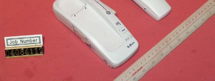
NYC-GH5877H
Sep 19, 20045.8GHz/2.4GHz 40 Channel Cordless Phone (Handset)
Equipment Class
DXX - Part 15 Low Power Communication Device Transmitter