NYLBTH-2102Bluetooth Wireless Handfree Kit
Racewood Technology Co. Ltd.
Click to zoom
Application Details
- Equipment Class
- DXT - Part 15 Low Power Transceiver, Rx Verified
- Date of Grant
- Oct 06, 2002
- Application Purpose
- Original Equipment
- Date of Application
- Oct 06, 2002
- Equipment Note
- Bluetooth Wireless Handfree Kit
- Frequency Range
- 2402.00000000 - 2480.00000000
- Company
- Racewood Technology Co. Ltd.
- Country
- Taiwan
Documents & Files
Document Text
Text extracted from the exhibit documents filed with the FCC. Open a document above to read the original.
External Photos
ETC Report No. : ET91R-08-044-02 FCC ID.: NYLBTH-2102 Rev. No 2.0 CONSTRUCTED PHOTOS of EUT Top View of EUT Bottom View of EUT ETC Report No. : ET91R-08-044-02 FCC ID.: NYLBTH-2102 Rev. No 2.0 CONSTRUCTED PHOTOS of EUT Front View of Adaptor Rear View of Adaptor
ID Label/Location Info
BLUETOOTH WIRELESS HEADFREE KIT LABEL POSITION Label Size: 17.5mm(L)*6.5mm(W) This statement will be placed in User Manual. This device complies with part 15 of the FCC Rules. Operation is subject to the following two conditions: 1. This device may not cause harmful interference. 2. This device must accept any interference received, including interference that may cause undesired operation. Model: BTH-2102 FCC ID.: NYLBTH-2102 LABEL
Internal Photos
ETC Report No. : ET91R-08-044-02 FCC ID.: NYLBTH-2102 Rev. No 2.0 CONSTRUCTED PHOTOS of EUT Internal View of EUT Component View of Main PCB ETC Report No. : ET91R-08-044-02 FCC ID.: NYLBTH-2102 Rev. No 2.0 CONSTRUCTED PHOTOS of EUT Solder View of Main PCB Front View of Battery ETC Report No. : ET91R-08-044-02 FCC ID.: NYLBTH-2102 Rev. No 2.0 CONSTRUCTED PHOTOS of EUT Rear View of Battery Internal View of Adaptor ETC Report No. : ET91R-08-044-02 FCC ID.: NYLBTH-2102 Rev. No 2.0 CONSTRUCTED PHOTOS of EUT Component View of Adaptor’s PCB Solder View of Adaptor’s PCB
Operational Description
BTH-2102 BT-EARLINE The headset profile defines the facilities required to make and receive hands-free voice calls from a headset to a cellular phone handset. Of course, it can also be used to transfer voice calls between other Bluetooth devices. Bluetooth headsets can be drived via buttons on the headset, but voice-activated command and control provides a more elegant interface, and should be popular for consumer headsets. The specification only assumes that there is some way for the user to initiate an action, and doesn’t specify how that will be done. The Bluetooth headset profile defines two roles: >>Audio Gataway(AG):This is the device that is the gateway of the audio, both for input and output(e.g., cellular phone, personal computer). >>Headset(HS):This is the device acting as the remote audio input and output mechanism. Figure 1. shows the protocol stack used by the Bluetooth headset profile. The audio port emulation layer is the entity emulating the audio port. This layer could reside on a cellular phone or PC. The audio driver is the driver software in the headset. Audio Gateway Headset Audio Port Emulation Application Headset Control SDP RFCOMM L2CAP Host Control Interface Link Manager Link Control Radio Audio Port Driver Application Headset Control SDP RFCOMM L2CAP Host Control Interface Link Manager Link Control Radio Establishing a Call to a Bluetooth Headset Figure 2 shows how an Audio Gateway establishes a call to Bluetooth headset. Usually, the Audio Gateway will initiate the connection to the headset because it has received an incoming call. For example, the Audio Gateway could be in a cellular phone handset. When the phone receives a phone call, it activates a Bluetooth connection and passes the call to headset. It is possible the some internal event could also cause the gateway to call the headset: for example, an application running on a PDA might send an alarm call with a pre-recorded message, warning the headset’s wearer of an appointment. The first step of the Audio Gateway establishing a call is to set up an ACL connection. This could be done by paging, or it could be done by unparking if the headset were previously parked for power saving. A parked device is already synchronised to its Master’s clock, so unparking would be faster than paging. For more details on parking and unparking. Once the ACL link is established, it can be used to send a ring tone. The ring tone is sent using an AT RING command as defined in ITU-T Recommendations V.250. The example in figure 2 uses a ting signal on the ACL link to signal a call. Alternatively, the SCO link could be set up earlier, and the ring signal sent on the SCO link, as shown in figure 3. Figure 2 Headset Ring signal on ACL link Audio Gateway Set up ACL connection Repeated ring sent Ring signal on ACL link AT+CkPD SCO voice link established Figure 3. Set up SCO connection Ring tone on SCO connection Audio Gateway Set up ACL Headset Repeated rings sent Ring tone on SCO link AT+CkPD Voice connected to SCO link
Test Report
Rev. No 2.0 FCC Part 15 EMI TEST REPORT of E.U.T. : Bluetooth Wireless HandFree Kit MODEL : BTH-2102 FCC ID. : NYLBTH-2102 for APPLICANT : RACEWOOD TECHNOLOGY CO., LTD. ADDRESS : 5F-2, No. 6, Chung-Hsing Rd., Sec. 1, Wu-Gu, Taipei, Taiwan 248, R.O.C. Test Performed by ELECTRONICS TESTING CENTER, TAIWAN NO. 34, LIN 5, DING FU TSUN, LINKOU HSIANG TAIPEI HSIEN, TAIWAN, R.O.C. Tel:(02)26023052, (02)26023052 Fax:(02)26010910 Report Number : ET91R-08-044-02 ETC Report No. : ET91R-08-044-02 FCC ID. : NYLBTH-2102 Rev. No 2.0 TEST REPORT CERTIFICATION Applicant : RACEWOOD TECHNOLOGY CO., LTD. 5F-2, No. 6, Chung-Hsing Rd., Sec. 1, Wu-Gu, Taipei, Taiwan 248, R.O.C. Manufacturer : RACEWOOD TECHNOLOGY CO., LTD. 5F-2, No. 6, Chung-Hsing Rd., Sec. 1, Wu-Gu, Taipei, Taiwan 248, R.O.C. Description of EUT : a) Type of EUT : Bluetooth Wireless HandFree Kit b) Trade Name : Racewood c) Model No. : BTH-2102 d) Power Supply : DC 3.7V Battery e) Working Frequency : 2400MHz~2483.5MHz Regulation Applied : FCC Rules and Regulations Part 15 Subpart C (2001) I HEREBY CERTIFY THAT: The data shown in this report were made in accordance with the procedures given in ANSI C63.4, and the energy emitted by the device was founded to be within the limits applicable. I assume full responsibility for accuracy and completeness of these data. Note: 1. The result of the testing report relate only to the item tested. 2. The testing report shall not be reproduced expect in full, without the written approval of ETC. Issued Date : Sep. 14, 2002 Test Engineer : ( S. S. Liou ) Approve & Authorized Signer : Will Yauo, Manager EMC Dept. II of ELECTRONICS TESTING CENTER, TAIWAN ETC Report No. : ET91R-08-044-02 FCC ID. : NYLBTH-2102 Rev. No 2.0 Table of Contents Page 1 GENERAL INFORMATION....................................................................................................... 1 1.1 Product Description...................................................................................................................... 1 1.2 Characteristics of Device ............................................................................................................. 1 1.3 Test Methodology......................................................................................................................... 1 1.4 Test Facility.................................................................................................................................. 1 2 PROVISIONS APPLICABLE...................................................................................................... 2 2.1 Definition...................................................................................................................................... 2 2.2 Requirement for Compliance ....................................................................................................... 3 2.3 Restricted Bands of Operation ..................................................................................................... 5 2.4 Labeling Requirement .................................................................................................................. 5 2.5 User Information........................................................................................................................... 6 3. SYSTEM TEST CONFIGURATION........................................................................................... 7 3.1 Justification................................................................................................................................... 7 3.2 Devices for Tested System ........................................................................................................... 7 4 RADIATED EMISSION MEASUREMENT............................................................................... 8 4.1 Applicable Standard ..................................................................................................................... 8 4.2 Measurement Procedure............................................................................................................... 8 4.3 Measuring Instrument................................................................................................................. 10 4.4 Radiated Emission Data ............................................................................................................. 11 4.5 Field Strength Calculation .......................................................................................................... 16 4.6 Photos of Radiation Measuring Setup ........................................................................................ 17 5 CONDUCTED EMISSION MEASUREMENT........................................................................ 18 5.1 Standard Applicable ................................................................................................................... 18 5.2 Measurement Procedure............................................................................................................. 18 5.3 Conducted Emission Data .......................................................................................................... 19 5.4 Result Data Calculation.............................................................................................................. 19 5.5 Conducted Measurement Equipment ......................................................................................... 19 5.6 Photos of Conduction Measuring Setup ..................................................................................... 20 6 ANTENNA REQUIREMENT.................................................................................................... 21 6.1 Standard Applicable ................................................................................................................... 21 6.2 Antenna Construction................................................................................................................. 21 7 BAND …
Text truncated - open the document above for the full version.
Test Setup Photos
ETC Report No. : ET91R-08-044-02 FCC ID. : NYLBTH-2102 Rev. No 2.0 Photos of Radiation Measuring Setup ETC Report No. : ET91R-08-044-02 FCC ID. : NYLBTH-2102 Rev. No 2.0 Photos of Conduction Measuring Setup
Contact Information
Applicant
Jason Ho(Engineer)
Test Firm
Electronics Testing Center, TaiwanWin-Po Tsai
Technical Specifications
| # | Rule Parts | Frequency Range | Power Output |
|---|---|---|---|
| 1 | 15C | 2.40 GHz - 2.48 GHz | - |
Other Applications from Racewood Technology Co. Ltd.

NYLBTH-2101
Oct 06, 2002Bluetooth Wireless Hand Free Kit
Equipment Class
DXT - Part 15 Low Power Transceiver, Rx Verified
NYLBTD-2403
Sep 09, 2002Bluetooth USB Dongle
Equipment Class
DXT - Part 15 Low Power Transceiver, Rx Verified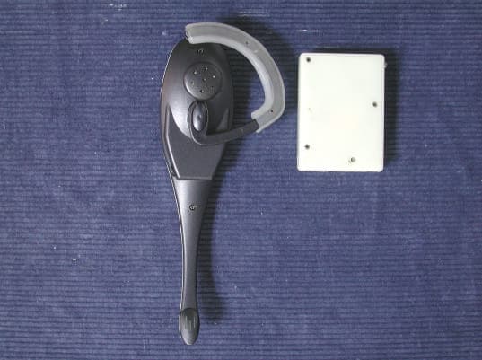
NYLSST900X
Oct 01, 2001Wireless Video Sender
Equipment Class
DXX - Part 15 Low Power Communication Device Transmitter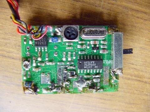
NYL24TXC01
May 14, 2001Wireless Camera Transmitter
Equipment Class
DXX - Part 15 Low Power Communication Device Transmitter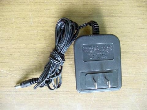
NYL24TXC02
May 08, 2001Wireless Camera Transmitter
Equipment Class
DXX - Part 15 Low Power Communication Device Transmitter