NYM-PLM-01
Axlon Electronics Corp.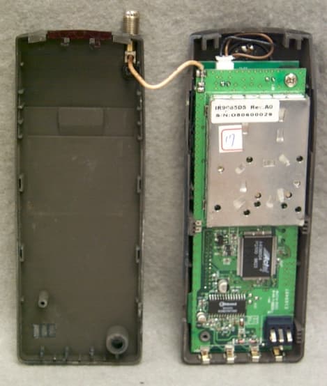
Click to zoom
Application Details
- Equipment Class
- DSS - Part 15 Spread Spectrum Transmitter
- Date of Grant
- Apr 09, 2000
- Application Purpose
- Original Equipment
- Date of Application
- Jan 04, 2000
- Frequency Range
- 905.72800000 - 924.16000000
- Company
- Axlon Electronics Corp.
- Country
- Taiwan
Documents & Files
Document Text
Text extracted from the exhibit documents filed with the FCC. Open a document above to read the original.
Users Manual
FCC ID: NYM-PLM-01 SECTION 6 USER'S MANUAL FCC ID: NYM-PLM-01 FCC ID: NYM-PLM-01 FCC ID: NYM-PLM-01 FCC ID: NYM-PLM-01 FCC ID: NYM-PLM-01 FCC ID: NYM-PLM-01 FCC ID: NYM-PLM-01 FCC ID: NYM-PLM-01 FCC ID: NYM-PLM-01 FCC ID: NYM-PLM-01 FCC ID: NYM-PLM-01 FCC ID: NYM-PLM-01 FCC ID: NYM-PLM-01 FCC ID: NYM-PLM-01 FCC ID: NYM-PLM-01 FCC ID: NYM-PLM-01 FCC ID: NYM-PLM-01 FCC ID: NYM-PLM-01 FCC ID: NYM-PLM-01 FCC ID: NYM-PLM-01 FCC ID: NYM-PLM-01 FCC ID: NYM-PLM-01 FCC ID: NYM-PLM-01 FCC ID: NYM-PLM-01 FCC ID: NYM-PLM-01
Users Manual
FCC ID: NYM-PLM-01 FCC ID: NYM-PLM-01 FCC ID: NYM-PLM-01 FCC ID: NYM-PLM-01 FCC ID: NYM-PLM-01 FCC ID: NYM-PLM-01 FCC ID: NYM-PLM-01 FCC ID: NYM-PLM-01 FCC ID: NYM-PLM-01 FCC ID: NYM-PLM-01 FCC ID: NYM-PLM-01 FCC ID: NYM-PLM-01 FCC ID: NYM-PLM-01 FCC ID: NYM-PLM-01 FCC ID: NYM-PLM-01 FCC ID: NYM-PLM-01 FCC ID: NYM-PLM-01 FCC ID: NYM-PLM-01 FCC ID: NYM-PLM-01 FCC ID: NYM-PLM-01 FCC ID: NYM-PLM-01 FCC ID: NYM-PLM-01 FCC ID: NYM-PLM-01 FCC ID: NYM-PLM-01
Cover Letter(s)
FCC ID: NYM-PLM-01
ID Label/Location Info
FCC ID: NYM-PLM-01 SECTION 3 LABELING INFORMATION FCC ID: NYM-PLM-01 FCC ID: NYM-PLM-01 FCC ID: NYM-PLM-01
Internal Photos
FCC ID: NYM-PLM-01 SECTION 5 PHOTOGRAPHS FCC ID: NYM-PLM-01 PHOTOS OF THE TESTED EUT The following photos are attached: Photo 1.EUT, Front View Including Antenna Photo 2.EUT, Front View Photo 3.EUT, Rear View Photo 4.EUT, Rear View, Battery Removed Photo 5.EUT, Cover Removed Photo 6.EUT, Top Side of Main Board Photo 7.EUT, Bottom Side of Main Board Photo 8.EUT, Top Side of Keypad Board Photo 9.EUT, Bottom Side of Keypad Board Photo 10.EUT, Top Side of LCD Display Board Photo 11.EUT, Bottom Side of LCD Display Board Photo 12.EUT, Top View of Transceiver Board FCC ID: NYM-PLM-01 Photo 1.EUT, Front View Including Antenna FCC ID: NYM-PLM-01 Photo 2.EUT, Front View FCC ID: NYM-PLM-01 Photo 3.EUT, Rear View FCC ID: NYM-PLM-01 Photo 4.EUT, Rear View, Battery Removed FCC ID: NYM-PLM-01 Photo 5.EUT, Cover Removed FCC ID: NYM-PLM-01 Photo 6.EUT, Top Side of Main Board FCC ID: NYM-PLM-01 Photo 7.EUT, Bottom Side of Main Board FCC ID: NYM-PLM-01 Photo 8.EUT, Top Side of Keypad Board FCC ID: NYM-PLM-01 Photo 9.EUT, Bottom Side of Keypad Board FCC ID: NYM-PLM-01 Photo 10.EUT, Top Side of LCD Display Board FCC ID: NYM-PLM-01 Photo 11.EUT, Bottom Side of LCD Display Board FCC ID: NYM-PLM-01 Photo 12.EUT, Top View of Transceiver Board FCC ID: NYM-PLM-01
Internal Photos
Photo 12.EUT, Top View of Transceiver Board with Shield Photo 13.EUT, Bottom View of Transceiver Board with Shield Photo 14.EUT, Top View of Transceiver Board with Shield Removed Photo 15.EUT, Bottom View of Transceiver Board with Shield Removed
RF Exposure Info
FCC ID: NYM-PLM-01 RF EXPOSURE INFO FCC ID: NYM-PLM-01 6.1 RF Safety Requirements to 2.1093 According to Section 3 of Supplement C to OET Bulletin 65, Part 15 Transmitters are categorically excluded from Routine Environmental Evaluation by measurement or precise computations unless otherwise required by the Commissions The unit under evaluation has an external antenna of 3 dBi gain with a measured output power output of 0.0682 Watts at the antenna terminals. Due to the low power of the EUT, environmental evaluation should be deemed unnecessary since the EUT’s operational frequency range is 902-928 MHz and the ERP is considerably less than 1.5 Watts.
RF Exposure Info
Operating Configurations: The unit is a handheld telephone handset which is typically used in the following fashions. 1) Held to ear and mouth like a typical handset. 2) Held by hands in fashion to program portions of the system it communicates with by observing information on the LCD display. 3) Unit is on special base that is used to charge it, but may be brought off hook to be used as a speaker phone in conjunction with the microphone built into the charging base. Modes of operation include transceiver for voice or data, idle mode of operation, including charging or non-charging of the batteries via separate charging cradle. Duty Cycle/Transmission Protocol The unit is for use as a telephone and requires a protocol that allows for both transmit and receive. Duty cycle corrections were based upon the following information as supplied by Axlon Electronics Corp. For purposes of averaging spurious emissions, the following correction was applied. Worse Case duty cycle per 100 msec = 4.5ms/9.0 ms = 50% Duty Cycle Correction = 20 log (0.50) = -6.0 dB
Schematics
FCC ID: NYM-PLM-01 SECTION 4 BLOCK DIAGRAM / SCHEMATIC FCC ID: NYM-PLM-01 FCC ID: NYM-PLM-01
Schematics
FCC ID: NYM-PLM-01 FCC ID: NYM-PLM-01
Test Report
FCC ID: NYM-PLM-01 2.9 Peak Radiated Spurious Emission in the Frequency Range 30 -10000 MHz (FCC Section 15.247(c)) A preliminary scan was performed on the EUT to determine frequencies that were caused by the transmitter portion of the product. Significant emissions that fell within restricted bands were then measured on an OAT’s site. Radiated measurements below 1 GHz were tested with a RBW = 120 kHz. Radiated measurements above 1 GHz were measured using a RBW = VBW = 1 MHz. The results of peak radiated spurious emissions falling within restricted bands are given in Table 4a (low), Table 4b, (mid), Table 4c (high) and Figure 5a-5e (low), Figure 5f-5i (mid) and Figure 5j-5m (high). FCC ID: NYM-PLM-01 Figure 5a Peak Radiated Spurious Emission 15.247(c) Low FCC ID: NYM-PLM-01 Figure 5b Peak Radiated Spurious Emission 15.247(c) Low FCC ID: NYM-PLM-01 Figure 5c Peak Radiated Spurious Emission 15.247(c) Low FCC ID: NYM-PLM-01 Figure 5d Peak Radiated Spurious Emission 15.247(c) Low FCC ID: NYM-PLM-01 Figure 5e Peak Radiated Spurious Emission 15.247(c) Low FCC ID: NYM-PLM-01 Figure 5f Peak Radiated Spurious Emission 15.247(c) Mid FCC ID: NYM-PLM-01 Figure 5g Peak Radiated Spurious Emission 15.247(c) Mid FCC ID: NYM-PLM-01 Figure 5h Peak Radiated Spurious Emission 15.247(c) Mid FCC ID: NYM-PLM-01 Figure 5i Peak Radiated Spurious Emission 15.247(c) Mid FCC ID: NYM-PLM-01 Figure 5j Peak Radiated Spurious Emission 15.247(c) High FCC ID: NYM-PLM-01 Figure 5k Peak Radiated Spurious Emission 15.247(c) High FCC ID: NYM-PLM-01 Figure 5l Peak Radiated Spurious Emission 15.247(c) High FCC ID: NYM-PLM-01 Figure 5m Peak Radiated Spurious Emission 15.247(c) High FCC ID: NYM-PLM-01 Test Date:December 4 & December 30, 1999 UST Project:99-772 Customer:Axlon Electronics Corp. Model:PLM-01 TABLE 4a PEAK RADIATED SPURIOUS EMISSIONS (Low) Freq. (GHz) Test Data* (dBm) @3m Amp. Gain (dB) Antenna Factor (dB) Cable Loss (dB) Results (uV/m) @3m FCC Limits (uV/m) @3m 1.590-61.1**35.327.43.1113.15000 2.390-64.634.830.63.9126.55000 2.700-60.334.931.24.2229.45000 3.624-60.234.633.95.2367.15000 4.530-64.934.234.07.1280.65000 * = Data adjusted by + 1 dB for high pass filter ** = Data adjusted by + 2.6 dB for high pass filter SAMPLE CALCULATION: RESULTS (uV/m @ 3m) = Antilog ((-61.1 – 35.3 + 27.4 + 3.1 + 107)/20) = 113.1 CONVERSION FROM dBm TO dBuV = 107 dB Tester Signature: Name: Tim R. Johnson FCC ID: NYM-PLM-01 Test Date:December 4 & December 30, 1999 UST Project:99-772 Customer:Axlon Electronics Corp. Model:PLM-01 TABLE 4b PEAK RADIATED SPURIOUS EMISSIONS (Mid) Freq. (GHz) Test Data* (dBm) @3m Amp. Gain (dB) Antenna Factor (dB) Cable Loss (dB) Results (uV/m) @3m FCC Limits (uV/m) @3m 2.700-54.434.931.24.2452.45000 3.660-60.134.634.05.3378.85000 4.570-61.034.234.17.2450.75000 5.490-62.134.035.97.8536.75000 * = Data adjusted by + 1 dB for high pass filter ** = Data adjusted by + 2.6 dB for high pass filter SAMPLE CALCULATION: RESULTS (uV/m @ 3m) = Antilog ((-54.4 - 34.9 + 31.2 + 4.2 + 107)/20) = 452.4 CONVERSION FROM dBm TO dBuV = 107 dB Tester Signature: Name: Tim R. Johnson FCC ID: NYM-PLM-01 Test Date:December 4 & December 30, 1999 UST Project:99-772 Customer:Axlon Electronics Corp. Model:PLM-01 TABLE 4c PEAK RADIATED SPURIOUS EMISSIONS (High) Freq. (GHz) Test Data* (dBm) @3m Amp. Gain (dB) Antenna Factor (dB) Cable Loss (dB) Results (uV/m) @3m FCC Limits (uV/m) @3m 1.607-61.9**35.227.43.1104.65000 2.770-60.934.931.34.2218.05000 3.699-58.834.634.15.3449.55000 4.620-58.234.234.27.4641.85000 * = Data adjusted by + 1 dB for high pass filter ** = Data adjusted by + 2.6 dB for high pass filter SAMPLE CALCULATION: RESULTS (uV/m @ 3m) = Antilog ((-61.9 - 35.2 + 27.4 + 3.1 + 107)/20) = 104.6 CONVERSION FROM dBm TO dBuV = 107 dB Tester Signature: Name: Tim R. Johnson FCC ID: NYM-PLM-01 2.10 Average Spurious Emission in the Frequency Range 30 - 10000 MHz (FCC Section 15.247(c)) The results of average radiated spurious emissions falling within restricted bands are given in Table 5a (low), Table 5b, (mid), Table 5c (high) and Figure 6. Since the EUT was not capable of continuous mode of transmit, average measurements were not possible. Therefore only duty cycle corrections were applied to the peak measurements. Duty cycle corrections were based upon the following information as supplied by Axlon Electronics Corp. Worse Case duty cycle per 100 msec = 4.5ms/9.0 ms = 50% Duty Cycle Correction = 20 log (0.50) = -6.0 dB FCC ID: NYM-PLM-01 Figure 6 Average Radiated Spurious Emission 15.247(c) Since the EUT was not capable of continuous mode of transmit, average measurements were not possible. Therefore only duty cycle corrections were applied to the peak measurements. FCC ID: NYM-PLM-01 Test Date:December 4 & December 30, 1999 UST Project:99-772 Customer:Axlon Electronics Corp. Model:PLM-01 TABLE 5a AVERAGE RADIATED SPURIOUS EMISSIONS (Low) Freq. (GHz) Test Data* (dBm) @3m Amp. Gain (dB) Antenna Factor (dB) Cable Loss (dB) Results (uV/m) @3m FCC Limits (uV/m) @3m 1.590-67.1**35.327.43.156.7500.0 2.390-70.634.830.63.963.4500.0 2.700-66.334.931.24.2114.9500.0 3.624-66.234.633.95.2184.0500.0 4.530-70.934.234.07.1140.6500.0 * = Data adjusted by + 1dB for high pass filter and 6.0 dB for duty cycle. ** = Data adjusted by + 2.6 dB for high pass filter and 6.0 dB for duty cycle. SAMPLE CALCULATION: RESULTS (uV/m @ 3m) = Antilog ((-67.1 – 35.3 + 27.4 + 3.1 + 107)/20) = 56.7 CONVERSION FROM dBm TO dBuV = 107 dB Tester Signature: Name: Tim R. Johnson FCC ID: NYM-PLM-01 Test Date:December 4 & December 30, 1999 Project:99-772 Customer:Axlon Electronics Corp. Model:PLM-01 TABLE 5b AVERAGE RADIATED SPURIOUS EMISSIONS (Mid) Freq. (GHz) Test Data* (dBm) @3m Amp. Gain (dB) Antenna Factor (dB) Cable Loss (dB) Results (uV/m) @3m FCC Limits (uV/m) @3m 2.700-60.434.931.24.2226.7500.0 3.660-66.134.634.05.3189.8500.0 4.570-67.034.234.17.2225.9500.0 5.490-68.134.035.97.8269.0500.0 * = Data adjusted by + 1dB for high pass filter and 6.0 dB for duty cycle. ** = Data…
Text truncated - open the document above for the full version.
Test Report
Axlon Electronics Corp. FCC Part 15, Certification Application PLM-01 March 10, 2000 MEASUREMENT/TECHNICAL REPORT COMPANY NAME: Axlon Electronics Corp. MODEL: PLM-01 FCC ID: NYM-PLM-01 DATE: March 10, 2000 This report concerns (check one): Original grant X Class II change_____ Equipment type: Deferred grant requested per 47 CFR 0.457(d)(1)(ii)? yes_____ No X If yes, defer until:_________________ date N.A. agrees to notify the Commission by N.A. date of the intended date of announcement of the product so that the grant can be issued on that date. Report prepared by: United States Technologies, Inc. 3505 Francis Circle Alpharetta, GA 30004 Phone Number: (770) 740-0717 Fax Number: (770) 740-1508 FCC ID: NYM-PLM-01 TABLE OF CONTENTS AGENCY AGREEMENT SECTION 1 GENERAL INFORMATION 1.1 Product Description 1.2 Related Submittal(s) SECTION 2 TESTS AND MEASUREMENTS 2.1 Configuration of Tested EUT 2.2 Test Facility 2.3 Test Equipment 2.4 Modifications 2.5 Test Procedure and Results 2.6 Antenna Description 2.7 Peak Power (Antenna Conducted at Antenna Terminal) 2.8 Antenna Conducted Spurious Emissions 2.9 Peak Radiated Spurious Emissions 2.10 Average Radiated Spurious Emissions 2.11 Minimum 6 dB Bandwidth 2.12 Power Spectral Density 2.13 Processing Gain 2.14 Power Line Conducted Emissions for Transmitter 2.15 Radiated Emissions for Digital Device & Receiver (if Applicable) 2.16 Power Line Conducted for Digital Device & Receiver (if Applicable) 2.17 Cordless Telephone Security Code Requirements SECTION 3 LABELING INFORMATION SECTION 4 BLOCK DIAGRAM(S)/ SCHEMATIC(S) SECTION 5 PHOTOGRAPHS SECTION 6 USER'S MANUAL FCC ID: NYM-PLM-01 LIST OF FIGURES AND TABLES FIGURES 1)Test Configuration 2) Photograph(s) for Spurious and Digital Device Emissions 3) Peak Power Output 4) Antenna Conducted Spurious Emissions 5) Peak Radiated Spurious Emissions 6) Average Radiated Spurious Emissions 7) Minimum 6 dB Bandwidth 8) Power Spectral Density TABLES 1)EUT and Peripherals 2) Test Instruments 3) Peak Power Output 4) Peak Radiated Spurious Emissions 5) Average Radiated Spurious Emissions 6) Power Spectral Density 7) Conducted Emissions Data (Transmitter) 8) Radiated Emissions Data (Digital Device) 9) Conducted Emissions Data (Digital Device) FCC ID: NYM-PLM-01 SECTION 1 GENERAL INFORMATION FCC ID: NYM-PLM-01 GENERAL INFORMATION 1.1Product Description The Equipment Under Test (EUT) is a Axlon Electronics Corp., Model PLM-01. The EUT is a 900 MHz Direct Sequence Spread Spectrum mobile unit and is part of the Palm Pal- lite home automation system. The system, with all of its resources provides a powerful and convenient control interface between the user and a wide range of automated systems such as security, lighting, HVAC, or personal computer. The EUT is a used in this system as a cordless telephone, a control keypad, and information terminal. The transceiver is designed to operate on the following frequencies: Channel Frequency (MHz) 1905.728 2907.776 3909.824 4911.872 5913.920 6915.968 7918.016 8920.064 9922.112 10924.160 FCC ID: NYM-PLM-01 1.2Related Submittal(s)/Grant(s) The EUT will be used with part of a system to send/receive data. The transceiver presented in this report will be used with another transceiver which has been submitted under FCC ID: NYM-PLB-01 The EUT is subject to the following authorizations: a) Certification as a transceiver b) Verification as a receiver and digital device The information contained in this report is presented for the Certification & Verification authorization(s) for the EUT. FCC ID: NYM-PLM-01 SECTION 2 TESTS AND MEASUREMENTS FCC ID: NYM-PLM-01 TEST AND MEASUREMENTS 2.1 Configuration of Tested System The sample was tested per ANSI C63.4, Methods of Measurement from Low-Voltage Electrical and Electronic Equipment in the Range of 9 kHz to 40 GHz (1992). Conducted and radiated emissions data were taken with the test receiver or spectrum analyzer's resolution bandwidth adjusted to 9 kHz and 120 kHz, respectively. All measurements are peak unless stated otherwise. The video filter associated with the spectrum analyzer was off throughout the evaluation process. Interconnecting cables were manipulated as necessary to maximize emissions. A block diagram of the tested system is shown in Figure 1. Test configuration photographs for spurious and fundamental emissions are shown in Figure 2. The sample used for testing was received by U.S. Technologies on October 29, 1999 in good condition. 2.2 Test Facility Testing was performed at US Tech's measurement facility at 3505 Francis Circle, Alpharetta, GA. This site has been fully described and submitted to the FCC, and accepted in their letter marked 31040/SIT. Additionally this site has also been fully described and submitted to Industry Canada (IC), and has been approved under file number IC2982. 2.3 Test Equipment Table 2 describes test equipment used to evaluate this product. 2.4 Modifications The following modifications were made by Axlon Electronics Corp. to bring the EUT into compliance with FCC Part 15 limits for the transmitter portion of the EUT: 1) Conductive Coating was applied to the inside of both halves of the plastic chassis. FCC ID: NYM-PLM-01 FIGURE 1 TEST CONFIGURATION Handset FCC ID: NYM-PLM-01 Test Date:December 4 - December 30, 1999 UST Project:99-772 Customer:Axlon Electronics Corp. Model:PLM-01 FIGURE 2a Photograph(s) for Spurious Emissions (Front) FCC ID: NYM-PLM-01 Test Date:December 4 - December 30, 1999 UST Project:99-772 Customer:Axlon Electronics Corp. Model:PLM-01 FIGURE 2b Photograph(s) for Spurious Emissions (Back) FCC ID: NYM-PLM-01 Test Date:December 4 - December 30, 1999 UST Project:99-772 Customer:Axlon Electronics Corp. Model:PLM-01 FIGURE 2c Photograph(s) for Digital Device Emissions (Front) FCC ID: NYM-PLM-01 Test Date:December 4 - December 30, 1999 UST Project:99-772 Customer:Axlon Electronics Corp. Model:PLM-01 FIGURE 2d Photograph(s) for Digital Device Emissions (Back) FCC ID: NYM-PLM-01 TABLE 1 EUT and …
Text truncated - open the document above for the full version.
Contact Information
Applicant
Johnson Wu(Manager)
886-2-26983336
Technical Contact
United States TechnologiesTimothy R Johnson
[email protected]770-740-0717
3505 Francis Circle · Alpharetta, Georgia · United States
Non-Technical Contact
United States TechnologiesTimothy R Johnson
[email protected]770-740-0717
Test Firm
US TechSandy McEnery
Technical Specifications
| # | Rule Parts | Frequency Range | Power Output |
|---|---|---|---|
| 1 | 15C | 905.728 MHz - 924.16 MHz | 68.00 mW |
Other Applications from Axlon Electronics Corp.
NYM-PLD-01
Apr 30, 2000Wireless I/O
Equipment Class
DSS - Part 15 Spread Spectrum Transmitter
NYM-PLW-01
Apr 03, 2000Wireless Doorphone
Equipment Class
DSS - Part 15 Spread Spectrum Transmitter
NYM-PLB-01
Mar 16, 2000System Base Controller
Equipment Class
DSS - Part 15 Spread Spectrum Transmitter