NZ3WS-WN518N2802.11BGN WIFI REPEATER
Winstars Technology Limited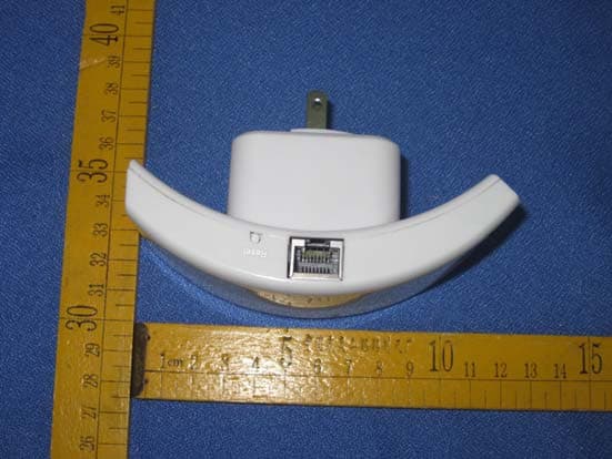
Click to zoom
Application Details
- Equipment Class
- JBP - Part 15 Class B Computing Device Peripheral
- Date of Grant
- Jul 10, 2012
- Application Purpose
- Original Equipment
- Date of Application
- Jul 10, 2012
- Equipment Note
- 802.11BGN WIFI REPEATER
- Company
- Winstars Technology Limited
- Country
- China
Documents & Files
Document Text
Text extracted from the exhibit documents filed with the FCC. Open a document above to read the original.
Users Manual
WiFi-Repeater User Manual Quick Installation Guide(Q.I.G.) REV.1.2 Introduction: The WiFi Repeater is a combined wired/wireless network connection device designed specifically for small business, office, and home office networking requirements. It allows a wireless network to be expanded using multiple access points without the need for a wired backbone to link them. It also works well with other 11b/g and 11n protocol wireless products. NOTE: If you need to reset the Wi-Fi Repeater, you need press and hold the reset button inside the tiny hole for 10 seconds. Package Contents Before you starting to use this router, please check if there’s anything missing in the package, and contact your dealer of purchase to claim for missing items: • 1 x Wireless-N Repeater • 1 x RJ-45 Networking Cable • 1 x Quick installation Guide Getting Started Setting up a Wireless Infrastructure Network For a typical wireless setup at home (as shown below), please do the following: Wireless Repeater Mode You will need WiFi AP/Router Internet access Wireless AP Mode You will need broadband Router Internet access Connect the WiFi-Repeater to your Router/Switch with RJ-45 Cable How to configure the Wi-Fi Repeater You can configure the Wi-Fi Repeater by connecting it with your computer/laptop with enclosed RJ45 cable or wirelessly. We recommend you to do it with wire. A. Configure the Wi-Fi Repeater with RJ45 Cable A1. Plug the Wi-Fi Repeater to a wall socket. Connect your computer / laptop with the Wi-Fi Repeater with enclosed RJ45 Cable. A2. Click the “ Start ” button (it should be located at the lower- left corner of your screen), then click “ Control Panel ”. Click “ View Network Status and Tasks ”, and then click “ Manage Network Connections ”. Right- click “ Local Area Network ”, then select “ Properties ”. When the “ Local Area Connection Properties ” window appears, select “I nternet Protocol Version 4 (TCP/IPv4) ” and then click “ Properties ”. A3. Setting IP address manually: Type IP address is 192.168.10.x ( x is from 2 to 254 ), and Subnet mask is 255.255.255.0 . Type the Router’s LAN IP address (the default IP is 192.168.10.1 ) into the Default gateway field. A4. Open web browser and type http://192.168.10.1 in the browser's address box. This number is the default IP address for this device. A5. The login screen below will appear. Enter the “User Name” and “Password” and click “OK” to login. The default User name is “admin” and the Password is “admin”. A6. After logging in and click “Setup Wizard”, you will see the web page below: Select “Wireless Repeater Mode (Station)” and click on ‘Next’ to continue. A7. Click on ‘Repeater – OneKey Setting’ button A8. Wait a few seconds and you will see the site below and please click on ‘Wireless Network Selection’ button. A9. Click on ‘Refresh List’ button. Select the Wireless SSID and click ‘Next’ to continue. A10. When you see the site below, please do not change any setting but only insert the password of your network. Click on ‘Apply and Reboot’ button. A11. Click ‘OK’ to confirm. The Repeater will restart. A12. Wait a few seconds and you will see the status site like below. It means your Wi-Fi Repeater is ready for use. * The Wi-Fi Repeater1 WLAN key is same with your router. If you do not see the site like above, you need to re-configure it again. NOTE: If you need to reset the Wi-Fi Repeater, you need press the reset button inside the tiny hole for 10 seconds. B. Configure the Wi-Fi Repeater wirelessly. 1. Plug the Wi-Fi Repeater to a wall socket. 2. Click on the network icon ( or ) on the right bottom of your desktop. You will find the signal from the Wi-Fi Repeater. Click on ‘Connect’ and wait for a few seconds. 3. Follow process A3 to A12 to configure your Wi-Fi Repeater wirelessly. C. Configure the Wireless AP Mode. 1. Plug the Wi-Fi Repeater to a wall socket. 2. Follow process A2 to A5. 3. Select “Standard Wireless AP Mode” and click on ‘Next’ to continue. 4. Click on ‘AP – OneKey Setting’ button 5. Wait a few seconds and you will see the status site like below. It means your Wi-Fi Repeater is ready for use. How to connect your computer/laptop with the Wi-Fi Repeater Adding a Wireless computers to the WiFi-Repeater 1. Log on to the computer. 2. Open Connect to a Network by right-clicking the network icon ( or ) in the notification area. 3. Choose the wireless network from the list that appears, and then click Connect . 4. Type the network security key or passphrase if you are asked to do so, and then click OK . You'll see a confirmation message when you are connected to the network. 5. To confirm that you added the computer, do the following: Open Network by clicking the Start button , and then clicking Control Panel . In the search box, type network , and then, under Network and Sharing Center, click View network computers and devices . You should see icons for the computer you added and for the other computers and devices that are part of the network. Note : If you don't see icons in the Network folder, then network discovery and file sharing might be turned off. Adding a wired (Ethernet) computer to the WiFi-Repeater 1. Plug the computer into WiFi-Repeater and then turn it on. 2. To confirm that you added the computer, do the following: Open Network by clicking the Start button , and then clicking Control Panel . In the search box, type network , and then, under Network and Sharing Center, click View network computers and devices . You should see icons for the computer you added and for the other computers and devices that are part of the network. For more information: http://windows.microsoft.com/en-US/windows7/Add-a-device-or-computer-to-a-network http://windows.microsoft.com/en-US/windows7/Setting-up-a-wireless-network http://windows.microsoft.com/en-US/windows-vista/Setting-up-a-wireless-network Configuring via Web Browser Wireless Base Configuration Please click “Wireless -> Basic Settings” located at the web management interface, the following…
Text truncated - open the document above for the full version.
Block Diagram
RT8020(U915) RTL8192CE(U1) SDRAM-U11 ( ISSIIS42S16800B-6TL ) 10/100M RJ45PORT RTL8196C(U17) L E D X140MHz ANT1 ANT2 DCPOWER MX25L1635DM2 1-12G(U19) RESET ACPOWER
External Photos
V1.0 Page 19 of 21 Report No.: CTL120509408-WD 6. External and Internal Photos of the EUT External Photos V1.0 Page 20 of 21 Report No.: CTL120509408-WD
ID Label/Location Info
FCCIDLabelInformation 1.Labellocation: 2.FCCIDLabel: WinstarsTechnologyLimitedWIFIRepeater Model:WS-WN518N2FCCID:NZ3WS-WN518N2 ThisdevicecomplieswithPart15oftheFCCRules.Operation issubjecttothefollowingtwoconditions:(1)thisdevicemay notcauseharmfulinterference,and(2)thisdevicemustaccept anyinterferencereceived,includinginterferencethatmaycause undesiredoperation.
Internal Photos
V1.0Page 21 of 21 ReportNo.:CTL120509408-WD InternalPhotos
Schematics
1 2 34 ABCD 4 3 2 1 D CBA Title Number Revision Size A4 Date: 8-May-2012 Sheet of File: D:\TDX OPEN 5W(1)\SCH.DDB Drawn By: L N D1~D4 1N4007*4 C2 4.7uF/400V C3 222/630V D5 FR107 D6 FR107 D7SB260 V+ F1 1A/250V 90-264VAC R21M C5 47uF/35V R10 15R C10 102/250V L2 C8 680uF/10V RTN PC1 PC817 R7 330 IC2PC817 IC2 TL431 TO-92 C9 104/50V R5 4.7K CY1 222/400V R85.1K C4 271/100V C7 680uF/10V C1 4.7uF/400V R2A1M R31K 1234 T1 EE16 IC1 THX202 123 4 56 R1 200K 7 8 L1 1mH C6103/50V R41K t THR1 5D-7 ZNR1 R1A 200K R9 10K R62.2K 05D471 TDX5W OPEN (5V1A) SCH 5 5 4 4 3 3 2 2 1 1 DD CC BB AA (DQM1) (DQM0) 16M 16bit SDARM x1 PCI-E Interface 10/100M PHY Interface LED Interface C224,C229 close to U17 UART Configure Interface Input 8 pins SPI Flash Single I/O Dual I/O Quad I/O R210=10K R212=10K SPI Flash 8 pins SPI R210=NC R212=NC Output Input A7 D8 D10 D1 A6 D5 A12 D15 RASB D14 D7 A5 D11 SD_CS0B A4 D13 A15 D6 D12 A8 A11 D9 D0 D4 A9 A16 D3 CASB D2 WEB RDIP4 TDON4 RDIN4 TDOP4 CLK-_HOST PERSTB HSOP HSIP HSON CLK+_HOST HSIN RESETB HSIP_E HSINHSIN_E HSIP SD_CLOCK JTGTDI WPS DEFAULT JTGTRST A0 A14 A10 A3 A13 A1 A2 SDRAM_CLK LED_PORT4 A11MA11 MSD_CS0BSD_CS0B A12MA12 MA3A3 MD14D14 MD1D1 MD3D3 WEBMWEB MD9D9 MA4A4 A14MA14 MA5A5 MD10D10 D5MD5 A6MA6 A13MA13 A2MA2 A8MA8 A10MA10 MA9A9 A0MA0 A1MA1 MD6D6 D15MD15 MD0D0 MD11D11 MD7D7 MA16A16 MD2D2 CASBMCASB MD4D4 D8MD8 A15MA15 MRASBRASB D13MD13 D12MD12 MA7A7 MD8 MA1 MA0 MRASB HSON MD12 MA5 JTGTDO MD4 RDIP4 AVDDX MD1 MA12 MA8 MD10 MD9 RDIN4 MD0 AVDDBG A17_SPIO3 MA4 MCASB MA14 MD13 MA16JTGTDI TDOP4 SF_CSB SF_SCK1 SD_CLOCK A20_SPIO0 MD7 TDON4 MA9 MSD_CS0B MD14 JTGCLK MA3 MD6MA15MA13 A19_SPIO1 MD2 MD15 JTGTMS MD5 MA11 HSOP MA6 MA7 MA2 PERSTB MWEB MD3 MD11 JTGTRST MA10 A18_SPIO2 CLK+_HOST CLK-_HOST AVDD10PCIE HSIP_E HSIN_E LED_PORT4 AVDD10PCIE VDD33_A VDD10_A U0RXD U0TXD CK_40M AVDD33USB CK_40M AVDD10USB WPSLEDJTGTMS U0TXD U0RXD 40M_SEL 40M_SEL ATEST WAKE# MA8 MA9 MA6 MA3 MA13 MA2 MA11 MA12 MA10 MA1 MA5 MA7 MA4 MA14 SYSLEDJTGTDO A20_SPIO0 A17_SPIO3 SF_SCK SF_CSB A19_SPIO1 A18_SPIO2 AVDDX CKE CKE SDRAM_CLK SF_SCK1SF_SCK WAKE# JTGCLK WAKEn PD# USBPOWER WAKEn AVDD10USB PD# USBPOWER USB0_DN USB0_DP USB0_DP USB0_DN JTGTMS JTGTDO JTGTRST JTGTDI JTGCLK TDOP0 TDON0 RDIP0 RDIN0 TDOP0TDON0RDIP0RDIN0 ATEST AVDD33USBAVDDBG GPIO55 GPIO33 GPIO22 GPIO22JTGCLK VDD33 VDD33 VDD33 VDD33 VDD10 VDD10 VDD10 VDD33VDD10 VDD33 VDD33 VDD33 VDD33 VDD33 VDD33 VDD33 VDD33 VDD10 VDD33 VDD10 VDD33 VDD10 VDD10 VDD33 VDD33 RDIN4{5} RDIP4{5} TDON4{5} TDOP4{5} CLK-_HOST{6} CLK+_HOST{6} HSON{6} PERSTB{6} HSIN{6} HSOP{6} HSIP{6} LED_PORT4{4} CK_40M{6} WAKE#{6} MA4{3} MA3{3} MA8{3} MA10{3} MA5{3} MA2{3} MA12{3} MA7{3} MA13{3} MA6{3} MA14{3} MA11{3} MA9{3} MA1{3} PD#{6} USBPOWER{4} USB0_DN{4} USB0_DP{4} GPIO55{4} GPIO33{4} GPIO22{4} Title SizeDocument NumberRev Date:Sheet of CPU/SDRAM/FLASH V311 Realtek 802.11n 10/100M Wireless Router Custom 27Thursday, April 07, 2011 Title SizeDocument NumberRev Date:Sheet of CPU/SDRAM/FLASH V311 Realtek 802.11n 10/100M Wireless Router Custom 27Thursday, April 07, 2011 Title SizeDocument NumberRev Date:Sheet of CPU/SDRAM/FLASH V311 Realtek 802.11n 10/100M Wireless Router Custom 27Thursday, April 07, 2011 C194 0.1uF C194 0.1uF R1590R1590 C192 0.1uF C192 0.1uF C234 0.1uF C234 0.1uF C225 0.1uF C225 0.1uF C200 0.1uF C200 0.1uF C252 0.1uF C252 0.1uF C236 0.1uF C236 0.1uF C197 0.1uF C197 0.1uF C201 0.1uF C201 0.1uF C233 10uF(0805) C233 10uF(0805) C246 1uF C246 1uF C195 0.1uF C195 0.1uF TP22TPTP22TP 1 1 C2060.1uFC2060.1uF C217 0.1uF C217 0.1uF R2162.5K(1%)R2162.5K(1%) R1610R1610 C101 0.1uF C101 0.1uF C220 10uF(0805) C220 10uF(0805) U11 ISSI IS42S16800B-6TL U11 ISSI IS42S16800B-6TL Vcc 1 DQ0 2 VccQ 3 DQ1 4 DQ2 5 VssQ 6 DQ3 7 DQ4 8 VccQ 9 DQ5 10 DQ6 11 VssQ 12 DQ7 13 Vcc 14 LDQM 15 WE 16 CAS 17 RAS 18 CS 19 BS0 20 BS1 21 A10/AP 22 A0 23 A1 24 A2 25 A3 26 Vcc 27 Vss 54 DQ15 53 VssQ 52 DQ14 51 DQ13 50 VccQ 49 DQ12 48 DQ11 47 VssQ 46 DQ10 45 DQ9 44 VccQ 43 DQ8 42 Vss 41 NC 40 UDQM 39 CLK 38 CKE 37 A12 36 A11 35 A9 34 A8 33 A7 32 A6 31 A5 30 A4 29 Vss 28 C253 1uF C253 1uF C2070.1uFC2070.1uF C216 10uF(0805) C216 10uF(0805) C248 0.1uF C248 0.1uF R1560R1560 C2290.1uFC2290.1uF J15 PIN1X4 J15 PIN1X4 C219 0.1uF C219 0.1uF C231 0.1uF C231 0.1uF R21310KR21310K R170 10K R170 10K C243 0.1uF C243 0.1uF C228 0.1uF C228 0.1uF C209 NC C209 NC TP21TPTP21TP 1 1 C202 0.1uF C202 0.1uF R8610R8610 L1110(0603)L1110(0603) R2180R2180 R169 10K R169 10K C198 0.1uF C198 0.1uF C204 10uF(0603) C204 10uF(0603) C191 0.1uF C191 0.1uF R20149.9R20149.9 J11 HEADER 6X2 (pitch=1.27mm) J11 HEADER 6X2 (pitch=1.27mm) 1 3 5 7 9 11 2 4 6 8 10 12 C193 0.1uF C193 0.1uF R210 10K R210 10K R2114.7KR2114.7K C199 0.1uF C199 0.1uF R173 10K R173 10K C242 0.1uF C242 0.1uF C241 0.1uF C241 0.1uF R1010R1010 R217 NC/10K R217 NC/10K R220NC/0R220NC/0 R187NC/10KR187NC/10K TP23TPTP23TP 1 1 R2080R2080 C224 0.1uF C224 0.1uF R212 10K R212 10K C211 0.1uF C211 0.1uF C235 0.1uF C235 0.1uF C227 0.1uF C227 0.1uF R172 10K R172 10K TP12 TP TP12 TP 1 1 R669 10K R669 10K U19 MX25L1635DM2I-12G/200mil(S08-wide) U19 MX25L1635DM2I-12G/200mil(S08-wide) CS 1 SO/SIO1 2 WP/SIO2 3 VSS 4 VCC 8 NC/SIO3 7 SCLK 6 SI/SIO0 5 R214 12K(1%) R214 12K(1%) TP24TPTP24TP 1 1 C205 1uF C205 1uF RTL8196C U17 RTL8196C RTL8196C U17 RTL8196C HSIP 122 PC I E _ RS T# 4 LED_PORT2 104 LED_PORT3 105 VDD10 103 VDD33 106 LED_PORT4 107 GPIOB7 108 HSOP 116 VDD10_USB 110 GND 111 HSON 115 AVDD33_USB_PCIE 114 USB_DP 113 USB_DN 112 AVDD10_PCIE 117 REFCLKN 118 REFCLKP 119 AGND_PCIE 120 HSIN 121 GPIOC0 109 AVDD33_25M 123 40M_SEL 124 40M_CLK 125 25M_XO 126 25M_XI 127 AVDD33_BG 128 R 12K 1 A GND _ SYSP LL 2 VDD 33 3 VDD 10 5 AVDD 10 6 T X O P0 7 TX ON0 8 R X I P0 9 RX I N0 10 AVDD 33 11 RX I N1 12 RX I P1 13 GND 14 T X ON1 15 T X O P1 16 AVDD 10 17 T X O P2 18 T X ON2 19 RX I P2 20 RX I N2 21 AVDD 33 22 RX I N3 23 RX I P3 24 T X ON3 25 T X O P3 26 AVDD 10 27 T X O P4 28 T X ON4 29 RX I P4 30 RX I N4 31 AVDD 33 32 I BREF 33 AVDD 10_ PHYP LL 34 ATEST 35 UAR T0_ RX 36 UAR T0_TX 37 TEST MO DE 38 VDD10 39 NF_CS1# 40 NF_CS…
Text truncated - open the document above for the full version.
Test Report
Shenzhen CTL Electromagnetic Technology Co., Ltd. Tel: +86-755-89486194 Fax: +86-755-89486187 MPE TEST REPORT FCC Per 47 CFR 2.1091(b) Report Reference No......................: FCC ID..............................................: CTL120509408-WF NZ3WS-WN518N2 Compiled by ( position+printed name+signature)..: File administrators Jacky Chen Name of the organization performing the tests ( position+printed name+signature)..: Test Engineer Nie Quan Approved by ( position+printed name+signature)..: Manager Tracy Qi Date of issue.....................................: July 09, 2012 Representative Laboratory Name.: Shenzhen CTL Electromagnetic Technology Co., Ltd. Address.............................................: Zone B, 4/F, Block 20, Guangqian Industrial Park, Longzhu Road, Nanshan, Shenzhen 518055 China. Test Firm..........................................: Bontek Compliance Testing Laboratory Ltd Address.............................................: 1/F, Block East H-3, OCT Eastern Ind. Zone, Qiaocheng East Road, Nanshan, Shenzhen, China Applicant’s name............................: Winstars Technology Limited Address.............................................: Block 4, Taisong Industrial Park, Dalang Street, Longhua Town, Bao'an District, Shenzhen, China Test specification: Standard ...........................................: FCC Per 47 CFR 2.1091(b) TRF Originator ..................................: Shenzhen CTL Electromagnetic Technology Co., Ltd. Master TRF.......................................: Dated 2011-01 Shenzhen CTL Electromagnetic Technology Co., Ltd. All rights reserved. This publication may be reproduced in whole or in part for non-commercial purposes as long as the Shenzhen CTL Electromagnetic Technology Co., Ltd. is acknowledged as copyright owner and source of the material. Shenzhen CTL Electromagnetic Technology Co., Ltd. takes no responsibility for and will not assume liability for damages resulting from the reader's interpretation of the reproduced material due to its placement and context. Test item description.................... : WIFI Repeater Trade Mark .......................................: / Operation Frequency........................: From 2400MHz to 2483.5MHz Model/Type reference.......................: WS-WN518N2 Listed Models ..................................: Result................................................: Positive V1.0 Page 2 of 8 Report No.: CTL120509408-WM T E S T R E P O R T Test Report No. : CTL120509408-WF July 09, 2012 ______________________________________________________________________________________________ Date of issue Equipment under Test : WIFI Repeater Model /Type : WS-WN518N2 Listed Models : / Applicant : Winstars Technology Limited Address : Block 4, Taisong Industrial Park, Dalang Street, Longhua Town, Bao'an District, Shenzhen, China Manufacturer : Winstars Technology Limited Address : Block 4, Taisong Industrial Park, Dalang Street, Longhua Town, Bao'an District, Shenzhen, China The test report merely corresponds to the test sample. It is not permitted to copy extracts of these test result without the written permission of the test laboratory. V1.0 Page 3 of 8 Report No.: CTL120509408-WM Contents 1. SUMMARY............................................................................. 4 1.1. EUT configuration 4 1.2. Power supply system utilised 4 1.3. Description of the test mode 4 1.4. NOTE 4 2. TEST ENVIRONMENT............................................................... 6 2.1. Address of the test laboratory 6 2.2. Environmental conditions 6 2.3. Statement of the measurement uncertainty 6 3. METHOD OF MEASUREMENT .................................................... 7 3.1. Applicable Standard 7 3.2. Limit 7 3.3. MPE Calculation Method 7 4. CONCLUSION ........................................................................ 8 V1.0 Page 4 of 8 Report No.: CTL120509408-WM 1. SUMMARY 1.1. EUT configuration The following peripheral devices and interface cables were connected during the measurement: ● - supplied by the manufacturer ○ - supplied by the lab ○ Power Cable Length (m) : / Shield : / Detachable : / ○ Multimeter Manufacturer : / Model No. : / 1.2. Power supply system utilised Power supply voltage : ● 120V / 60 Hz ○ 115V / 60Hz ○ 12 V DC ○ 24 V DC ○ Other (specified in blank below) 1.3. Description of the test mode IEEE 802.11b/g/n: Thirteen channels are provided to the EUT,but only eleventh channels used for USA. Channel Frequency(MHz)ChannelFrequency(MHz) 1 241282447 2 241792452 3 2422102457 4 2427112462 5 2432 6 2437 7 2442 1.4. NOTE The EUT is an 802.11b/g/n WIFI Repeater,The functions of the EUT listed as below: Test StandardsReference Report WLAN 802.11b/g, 802.11n FCC Part 15 Subpart C (Section15.247) CTL120509408-WF WLAN 802.11b/g, 802.11n FCC Per 47 CFR 2.1091(b) CTL120509408-WM 2. The frequency bands used in this EUT are listed as follows: Frequency Band(MHz)2400-2483.55150-53505470-5725 5725-5850 802.11b √ - - - 802.11g √ - - - 802.11n(20MHz) √ - - - 802.11n(40MHz) √ - - - V1.0 Page 5 of 8 Report No.: CTL120509408-WM 3. The EUT incorporates a MIMO function,Physically,the EUT provides two completed transmitter and two completed receivers. Modulation Mode TX Function 802.11b 1TX 802.11g 1TX 802.11n (20MHz) 2TX 802.11n (40MHz) 2TX V1.0 Page 6 of 8 Report No.: CTL120509408-WM 2. TEST ENVIRONMENT 2.1. Address of the test laboratory Bontek Compliance Testing Laboratory Ltd 1/F, Block East H-3, OCT Eastern Ind. Zone, Qiaocheng East Road, Nanshan, Shenzhen, China The sites are constructed in conformance with the requirements of ANSI C63.7, ANSI C63.4 (2003) and CISPR Publication 22. 2.2. Environmental conditions During the measurement the environmental conditions were within the listed ranges: Temperature: 15-35 ° C Humidity: 30-60 % Atmospheric pressure: 950-1050mbar 2.3. Statement of the measurement uncertainty The data and results referenced in this document are true and accurate. The reader is cautioned that th…
Text truncated - open the document above for the full version.
Test Report
Shenzhen CTL Electromagnetic Technology Co., Ltd. Tel: +86-755-89486194 Fax: +86-755-89486187 FCC PART 15 SUBPART B TEST REPORT FCC Part 15B Report Reference No......................: CTL120509408-WD Compiled by ( position+printed name+signature)..: File administrators Jacky Chen Name of the organization performing the tests ( position+printed name+signature)..: Test Engineer Nie Quan Approved by ( position+printed name+signature)..: Manager Tracy Qi Date of issue.....................................: July 09, 2012 Representative Laboratory Name.: Shenzhen CTL Electromagnetic Technology Co., Ltd. Address.............................................: Zone B, 4/F, Block 20, Guangqian Industrial Park, Longzhu Road, Nanshan, Shenzhen 518055 China. Test Firm..........................................: Bontek Compliance Testing Laboratory Ltd Address.............................................: 1/F, Block East H-3, OCT Eastern Ind. Zone, Qiaocheng East Road, Nanshan, Shenzhen, China Applicant’s name............................: Winstars Technology Limited Address.............................................: Block 4, Taisong Industrial Park, Dalang Street, Longhua Town, Bao'an District, Shenzhen, China Test specification: Standard ...........................................: FCC Part 15B: Unintentional Radiators TRF Originator ..................................: Shenzhen CTL Electromagnetic Technology Co., Ltd. Master TRF.......................................: Dated 2011-01 Shenzhen CTL Electromagnetic Technology Co., Ltd.. All rights reserved. This publication may be reproduced in whole or in part for non-commercial purposes as long as the Shenzhen CTL Electromagnetic Technology Co., Ltd. is acknowledged as copyright owner and source of the material. Shenzhen CTL Electromagnetic Technology Co., Ltd. takes no responsibility for and will not assume liability for damages resulting from the reader's interpretation of the reproduced material due to its placement and context. Test item description .................... : WIFI Repeater Trade Mark .......................................: / Model/Type reference.......................: WS-WN518N2 I/O Type of EUT................................: RJ45 port I/O Q’TY............................................: 1 Antenna Type..............................: Interior FCC ID.......................................: NZ3WS-WN518N2 Result................................................: Positive V1.0 Page 2 of 21 Report No.: CTL120509408-WD T E S T R E P O R T Test Report No. : CTL120509408-WD July 09, 2012 ______________________________________________________________________________________________ Date of issue Equipment under Test : WIFI Repeater Model /Type : WS-WN518N2 Listed Models : / Applicant : Winstars Technology Limited Address : Block 4, Taisong Industrial Park, Dalang Street, Longhua Town, Bao'an District, Shenzhen, China Manufacturer : Winstars Technology Limited Address : Block 4, Taisong Industrial Park, Dalang Street, Longhua Town, Bao'an District, Shenzhen, China Test Result according to the standards on page 4: Positive The test report merely corresponds to the test sample. It is not permitted to copy extracts of these test result without the written permission of the test laboratory. V1.0 Page 3 of 21 Report No.: CTL120509408-WD Contents 1. TEST STANDARDS .................................................................. 4 2. SUMMARY............................................................................. 5 2.1. General Remarks 5 2.2. Equipment Under Test 5 2.3. Short description of the Equipment under Test (EUT) 5 2.4. EUT operation mode 5 2.5. EUT configuration 5 2.6. Related Submittal(s) / Grant (s) 6 2.7. Modifications 6 3. TEST ENVIRONMENT............................................................... 7 3.1. Address of the test laboratory 7 3.2. Test Facility 7 3.3. Environmental conditions 7 3.4. Configuration of Tested System 7 3.5. Statement of the measurement uncertainty 8 3.6. Equipments Used during the Test 8 3.7. Summary of Test Result 8 4. TEST CONDITIONS AND RESULTS ............................................ 10 4.1. Conducted Emissions Test 10 4.2. Radiated Emissions Test 13 5. TEST SETUP PHOTOS OF THE EUT .......................................... 18 6. EXTERNAL AND INTERNAL PHOTOS OF THE EUT ....................... 19 V1.0 Page 4 of 21 Report No.: CTL120509408-WD 1. TEST STANDARDS The tests were performed according to following standards: FCC Part 15B : Unintentional Radiators ANCI C63.4: 2003 V1.0 Page 5 of 21 Report No.: CTL120509408-WD 2. SUMMARY 2.1. General Remarks Date of receipt of test sample : June 20, 2012 Testing commenced on : June 20, 2012 Testing concluded on : June 30, 2012 2.2. Equipment Under Test Power supply system utilised Power supply voltage : ●120V / 60 Hz o 115V / 60Hz o 12 V DC o 24 V DC o Other (specified in blank below) 2.3. Short description of the Equipment under Test (EUT) The device is a WIFI Repeater. For more details, refer to the user’s manual of the EUT. Serial number: Prototype 2.4. EUT operation mode Test Mode: 1. The EUT has been tested under normal operating condition. 2. No test program used to control the EUT within testing. 3. EUT Function and Test Mode. The field strength of radiation emission was measured in the following position: EUT stand-up position (Y axis), lie-down position (X, Z axis). The following data show only with the worst case setup. The worst case of Y axis was reported. Based on client request, all normal using modes of the normal function were tested but only the worst test data of the worst mode is reported by this report. 2.5. EUT configuration The following peripheral devices and interface cables were connected during the measurement: o - supplied by the manufacturer ● - supplied by the lab ● Mouse Manufacturer : DELL Model No. : MOC5UO ● Notebook PC Manufacturer : SONY Coporation Model No. : PCG-41216W V1.0 Page 6 of 21 Report No.: CTL120509408-WD 2.6. Rel…
Text truncated - open the document above for the full version.
Test Setup Photos
V1.0 Page 18 of 21 Report No.: CTL120509408-WD 5. Test Setup Photos of the EUT
Contact Information
Applicant
Johnson Huang(General Manager)
Test Firm
Bontek Compliance Testing Laboratory LtdTony Wu
Technical Specifications
| # | Rule Parts | Frequency Range | Power Output |
|---|---|---|---|
| 1 | 15B | - | - |
Other Applications from Winstars Technology Limited
NZ3-WN0009
Mar 03, 2026AX3000 WIFI6 Mesh Router
Equipment Class
NII - Unlicensed National Information Infrastructure TX
NZ3-WN0007
Jul 13, 2024Wireless AP/Repeater
Equipment Class
NII - Unlicensed National Information Infrastructure TXNZ3-WN0006
Jan 21, 2024WiFi 6E Tri-Band AX5400 PCI-E Adapter
Equipment Class
DTS - Digital Transmission System
NZ3-WN0004
Jan 12, 2023AX1800 Dual-Band Mesh WiFi Router Kit
Equipment Class
NII - Unlicensed National Information Infrastructure TX
NZ3-WN0003
Nov 13, 2022High Power Wireless Repeater
Equipment Class
NII - Unlicensed National Information Infrastructure TX